Brief communication: A fast vortex-based smearing correction for the actuator line
←
→
Page content transcription
If your browser does not render page correctly, please read the page content below
Wind Energ. Sci., 5, 349–353, 2020
https://doi.org/10.5194/wes-5-349-2020
© Author(s) 2020. This work is distributed under
the Creative Commons Attribution 4.0 License.

                      Brief communication: A fast vortex-based
                       smearing correction for the actuator line
                       Alexander R. Meyer Forsting, Georg R. Pirrung, and Néstor Ramos-García
            DTU Wind Energy, Technical University of Denmark, Frederiksborgvej 399, 4000 Roskilde, Denmark
                                Correspondence: Alexander R. Meyer Forsting (alrf@dtu.dk)

                                 Received: 18 September 2019 – Discussion started: 10 October 2019
                         Revised: 27 January 2020 – Accepted: 20 February 2020 – Published: 23 March 2020

       Abstract. The actuator line is a lifting line representation of aerodynamic surfaces in computational fluid dy-
       namics applications but with non-singular forces, which reduces the self-induced velocities at the line. The
       vortex-based correction by Meyer Forsting et al. (2019a) recovers this missing induction and thus the intended
       lifting line behaviour of the actuator line. However, its computational cost exceeds that of existing tip corrections
       and quickly grows with blade discretization. Here we present different methods for reducing its computational
       cost to the level of existing corrections without jeopardizing the stability or accuracy of the original method. The
       cost is reduced by at least 98 %, whereas the power is maximally affected by 0.8 % with respect to the original
       formulation. This accelerated smearing correction remains a dynamic correction by modelling the variation in
       trailed vorticity over time. The correction is openly available (Meyer Forsting et al., 2019b).

1   Introduction                                                    the correction, the AL truly functions as a LL, which was
                                                                    verified over the entire operational wind speed range of mod-
The actuator line (AL) Sørensen and Shen (2002) is a lifting        ern turbines as well as in yaw and for dynamic pitch steps
line (LL) representation of aerodynamic surfaces in Eulerian        (Meyer Forsting et al., 2019a). The numerical stability of the
computational fluid dynamics (CFD) applications. It allows          correction was not challenged by any of those flow cases –
simulating the interaction between the atmosphere and wind          not even by extreme inflow turbulence.
farms, as it captures all the important flow features of fully         The only disadvantage of the new smearing correction is
resolved rotors, at a fraction of the computational cost. How-      its computational cost. Though it is incorrect to apply con-
ever transferring a LL into the CFD domain requires dispers-        ventional tip corrections to ALs – they correct actuator discs
ing the concentrated blade forces of the LL over a certain re-      for missing discrete blades – their low cost makes them at-
gion – most commonly in the form of a Gaussian projection –         tractive. In this paper we present different methods that re-
to avoid causing numerical instabilities. This force smearing       duce the computational cost of the new correction to that of
leads to the formation of a viscous core in the released vor-       existing corrections without jeopardizing the stability or ac-
ticity, which subsequently reduces the induced velocity at the      curacy of the method.
blade (Dag, 2017; Meyer Forsting et al., 2019a; Martínez-
Tossas and Meneveau, 2019). Lower induction implies larger
angles of attack and thus increased blade forces. Especially        2   Methods for increasing speed
in regions presenting large load changes, as around the root
and tip of the blade, does the AL thus overestimate the forces.     Computing the missing induction requires re-evaluating the
   Meyer Forsting et al. (2019a) – following the approach           velocity contribution from each previously released vortex
proposed by Dag (2017) – presented a correction to the AL           element at each time step. The velocity contribution from
that combines the fast and dynamic near-wake model by Pir-          a single trailed vortex at some point along the blade is ob-
rung et al. (2016, 2017a, b) with a viscous core model (Lamb,       tained by integrating along the vortex line
1932; Oseen, 1911) to recover the missing induction. With

Published by Copernicus Publications on behalf of the European Academy of Wind Energy e.V.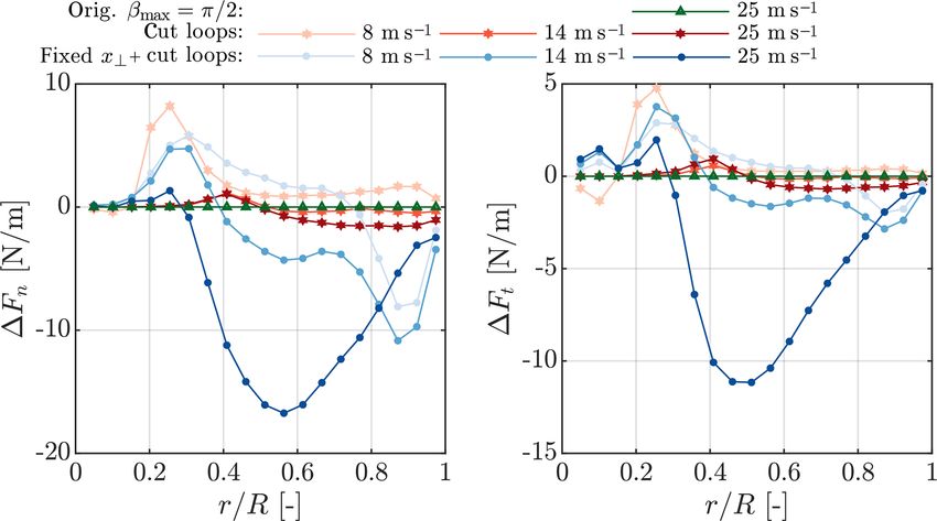
350 A. R. Meyer Forsting et al.: A vortex-based smearing correction
Different ratios were tested; however I = 0.99 – correspond-
Z∞ ing to rmax = 1.83 – provides a beneficial balance between
? accuracy and speed.
u = f δ ũ dl. (1)
0
2.3 Constant smearing factor, f (fixed x⊥ )
Here δ ũ is the velocity induced by an infinitesimal element
δl of a vortex line and f represents the smearing factor, A more radical approach than just reducing the wake length,
originating from the presence of a viscous core in the re- as described in Sect. 2.1, is fixing the perpendicular distance
leased vorticity. Integrating over the vortex length is equiva- between the vortex and blade element and thus the smear-
lent to integrating over time, as at each time step an element ing factor. In the three-dimensional formulation the smearing
is released. Originally, the near-wake model by Pirrung et al. factor is given by (Meyer Forsting et al., 2019a)
(2016, 2017a, b) provides directly the integrated velocities
|x ⊥ (r, β, h, φ)|2
ũ.1 It was only broken into elements, as f is a function of f = exp − (4)
the perpendicular distance from the vortex to the blade ele- 2
ment, which varies in time. As the distance changes at each with the perpendicular distance
time step, the velocity contribution from each vortex element
also needs to be updated each time step. Hence the more vor- tan φ (β cos β − sin β)
tex lines, the costlier the correction becomes. x ⊥ = r cos φ − tan φ (−1 + h/r + cos β + β sin β) . (5)
−1 + (1 − h/r) cos β
2.1 Reduce wake length (orig. βmax = π/2) The greatest simplification is achieved by setting β = 0, such
In the work verifying the smearing correction by that x ⊥ becomes the distance between vortex trailing point
Meyer Forsting et al. (2019a), the integration along the and blade section, which is a geometric constant for rigid
vortex lines was performed until βmax = 2π , where β de- blades.
fines the rotation angle, to ensure most induction is captured.
|x ⊥ (β = 0)| = h (6)
However, the near-wake model is devised to provide only the
induction from the vortex lines until β = π/2. Considering The smearing factor no longer needs to be updated for all
that the vortex core effect is only active in the near-wake, vortex elements at each time step, and the velocity correction
βmax could equally be set to π/2, thus reducing the number in Eq. (1) simply becomes
of vortex elements significantly.
u? = f ũ, (7)
2.2 Reduce inner loops (cut loops)
where ũ is directly determined by the near-wake model. Thus
The computational cost of vortex methods grows with the it is very computationally efficient and does not require sav-
square of the blade elements, which could lead to escalating ing and integrating the induced velocities from discretized
costs with increasing discretization. Usually, the induction vortex arcs. At each time step and for each blade section, the
of each vortex line on each blade section needs to be deter- influence from each previously trailed vortex arc can be sim-
mined. Yet the limited size of the viscous core allows short- ply updated by multiplying with an exponential decay factor
cutting this procedure by considering only the blade sections and adding the influence of the newly trailed element (Pir-
closest to the vortex line. The velocity missing in AL simu- rung et al., 2016). In this paper this method is run in con-
lations in two dimensions is given by junction with the cutting loops approach.
f
z }| { 3 Results
v ? (r, ) = ṽ exp(−r 2 / 2 ), (2)
This section compares the influence of the different speed-
with r representing the distance from the vortex core and up methods presented in Sect. 2 with the original results
the force smearing length scale. To determine the size of the of Meyer Forsting et al. (2019a). All results are obtained
vortex core rmax , the ratio between cut and fully resolved vor- with exactly the same computational set-up as presented in
tex core is computed: Sect. 3 of the same paper. The AL models the NREL 5 MW
R rmax ? (Jonkerman et al., 2009) under uniform inflow. For the in-
v (r, ) dr flow wind speed specific turbine parameters refer to Table 2
I = R0 ∞ ? . (3)
in Meyer Forsting et al. (2019a).
0 v (r, ) dr
Figure 1 compares the force distributions for the NREL
1 Note that the integration only covers the near-wake region, 5 MW at two wind speeds obtained with the speed-up meth-
from 0 to π/2. ods presented in Sect. 2 to those obtained with the original
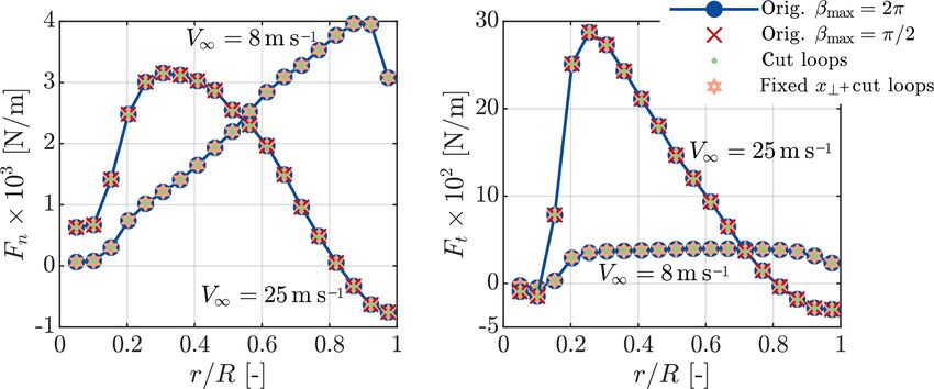
Wind Energ. Sci., 5, 349–353, 2020 www.wind-energ-sci.net/5/349/2020/A. R. Meyer Forsting et al.: A vortex-based smearing correction 351 Figure 1. Normal and tangential forces on the NREL 5 MW blades at 8 and 25 m s−1 predicted by AL simulations (blades discretized by 19 sections) with smearing correction and different computational speed-up methods. The reference is the original formulation (orig.) with βmax = 2π . Figure 2. Difference in normal and tangential forces over the NREL 5MW blades at 8, 14 and 25 m s−1 predicted by AL simulations (blades discretized by 19 sections) with different smearing correction speed-up methods with respect to simulations without speed-up. model. The influence of reducing the wake length is only A full result overview – the impact of the speed-up meth- shown for a wind speed of 25 m s−1 , but it is similar at lower ods on thrust and power as well as their influence on the wind speeds. With increasing wind speed, the peak force computational cost per blade – is given in Table 1. Results moves clearly from the tip to the root whilst the smearing are shown for rotors discretized by 9 and 19 blade sections. correction ensures the smooth behaviour towards the blade Firstly, the greatest change in thrust or power across all meth- ends. From pure visual inspection there is no change in the ods occurs when fixing the smearing constant, yet never by forces when applying any of the speed-up options. To high- more than 0.8 % and only at the highest wind speed. The light their impact, only the change in the force distributions positive influence of cutting the inner loops on performance with respect to the unmodified model is shown in Fig. 2 – grows with increasing resolution. However, the largest reduc- here additionally the results for a wind speed of 14 m s−1 are tion in the computational cost comes from limiting the wake presented. Reducing the wake length has a negligible effect length and ultimately fixing the smearing factor. With the lat- on the forces as does reducing the inner loops, except close ter approach the longest of all smearing correction iterations to the root. Fixing the smearing factor additionally to cutting lasted 8 × 10⁻⁴ s. the loops has the largest influence. However even at 25 m s−1 the deviation does not exceed 17 N m−1 . With respect to the local force the difference remains below 1 %. www.wind-energ-sci.net/5/349/2020/ Wind Energ. Sci., 5, 349–353, 2020
352                                                              A. R. Meyer Forsting et al.: A vortex-based smearing correction

Table 1. An overview of the influence of the computational speed-up methods on thrust, power and computational cost per blade for two
different blade discretizations – 9 and 19 blade sections. Only for the original model are the nominal values shown, otherwise the relative
change to the original is given in percent.

              Ns              V∞ (m s−1 )     Orig. βmax = 2π     Orig. βmax = π/2 (%)           Cut loops (%)   Fixed x⊥ (%)
              9     Thrust               8    406 kN                                         –    1.96 × 10⁻²    −3.83 × 10⁻²
                                        14    466 kN                                         –    1.35 × 10⁻²    −1.79 × 10⁻¹
                                        25    286 kN                        4.43 × 10⁻³          −2.06 × 10⁻²    −5.65 × 10⁻¹
                    Power                8    2.11 MW                                 –           4.37 × 10⁻²    −1.37 × 10⁻¹
                                        14    5.43 MW                                 –           1.88 × 10⁻²    −2.75 × 10⁻¹
                                        25    5.47 MW                       6.78 × 10⁻³          −2.28 × 10⁻²    −7.95 × 10⁻¹
                    Cost                 8    8.68 × 10⁻³ s                           –                 −43.5           −99.3
                                        14    9.91 × 10⁻³ s                           –                 −44.9           −98.3
                                        25    1.04 × 10⁻² s                       −83.4                 −45.9           −99.4
              19    Thrust               8    394 kN                                         –    9.13 × 10⁻²     2.81 × 10⁻²
                                        14    456 kN                                         –   −7.40 × 10⁻⁴    −9.81 × 10⁻²
                                        25    277 kN                        8.73 × 10⁻⁵          −3.30 × 10⁻²    −4.75 × 10⁻¹
                    Power                8    2.00 MW                                 –           1.71 × 10⁻¹     1.43 × 10⁻²
                                        14    5.28 MW                                 –          −1.80 × 10⁻³    −1.56 × 10⁻¹
                                        25    5.29 MW                       1.32 × 10⁻⁴          −4.36 × 10⁻²    −6.83 × 10⁻¹
                    Cost                 8    4.35 × 10⁻² s                           –                 −63.3           −99.0
                                        14    4.45 × 10⁻² s                           –                 −63.7           −98.2
                                        25    4.37 × 10⁻² s                       −82.9                 −62.6           −99.0

4   Conclusions                                                         Code availability. All data are available on request. Commercial
                                                                        and research licences for EllipSys3D can be purchased from DTU.
The smearing correction by Meyer Forsting et al. (2019a)                The source code of the fast smearing correction is openly available
recovered the lifting line behaviour of the actuator line, how-         (Meyer Forsting et al., 2019b).
ever at a larger computational cost than existing actuator disc
tip corrections. This paper presents different methods for re-
ducing the cost of the smearing correction to those levels.             Competing interests. The authors declare that they have no con-
The number of wake elements manifests itself as the key cost            flict of interest.
driver. Reducing the wake length therefore significantly re-
duces the computational cost without negatively impacting
                                                                        Special issue statement. This article is part of the special issue
the blade forces. The greatest speed-up comes from utiliz-
                                                                        “Wind Energy Science Conference 2019”. It is a result of the Wind
ing the near-wake model to avoid recomputing the contribu-
                                                                        Energy Science Conference 2019, Cork, Ireland, 17–20 June 2019.
tions from each element at each time step, leading to a fall
in the cost of at least 98 %. This is accompanied by changes
in thrust and power of maximally 0.8 % and 0.7 %, respec-               Acknowledgements. We would like to acknowledge DTU Wind
tively. Still, with respect to the great gain in performance            Energy’s internal project Virtual Atmosphere for partially funding
this is acceptable and lies well within CFD simulation uncer-           this research.
tainty. Furthermore, the new, faster method avoids any form
of bookkeeping, greatly simplifying the implementation of
the smearing correction. It also remains a dynamic correc-              Financial support. This research has been supported by the DTU
tion that takes into account how the trailed vorticity changes          Wind Energy (project Virtual Atmosphere).
over time and moves away from the blades. This faster and
simpler version of the smearing correction is openly avail-
able (Meyer Forsting et al., 2019b).                                    Review statement. This paper was edited by Rebecca Barthelmie
                                                                        and reviewed by David Wood and Claudio Balzani.

Wind Energ. Sci., 5, 349–353, 2020                                                                  www.wind-energ-sci.net/5/349/2020/
A. R. Meyer Forsting et al.: A vortex-based smearing correction 353
References Oseen, C.: Über Wirbelbewegung in einer reibenden Flüssigkeit,
Arkiv för matematik, astronomi och fysik, Ark. Mat. Astron.
Dag, K.: Combined pseudo-spectral/actuator line model for wind Fys., 7, 14–21, 1911.
turbine applications, PhD thesis, DTU Wind Energy, Denmark, Pirrung, G., Madsen, H. A., Kim, T., and Heinz, J.: A coupled near
2017. and far wake model for wind turbine aerodynamics, Wind En-
Jonkman, J., Butterfield, S., Musial, W., and Scott, G.: Definition ergy, 19, 2053–2069, https://doi.org/10.1002/we.1969, 2016.
of a 5-MW reference wind turbine for offshore system devel- Pirrung, G., Riziotis, V., Madsen, H., Hansen, M., and Kim,
opment, Tech. rep., NREL/TP-500-38060, National Renewable T.: Comparison of a coupled near- and far-wake model
Energy Laboratory (NREL), Colorado, USA, 2009. with a free-wake vortex code, Wind Energ. Sci., 2, 15–33,
Lamb, H.: Hydrodynamics, C.U.P., 6th Edn., Cambridge University https://doi.org/10.5194/wes-2-15-2017, 2017a.
Press, Cambridge, 1932. Pirrung, G. R., Madsen, H. A., and Schreck, S.: Trailed vortic-
Martínez-Tossas, L. A. and Meneveau, C.: Filtered lifting line the- ity modeling for aeroelastic wind turbine simulations in stand-
ory and application to the actuator line model, J. Fluid Mech., still, Wind Energ. Sci., 2, 521–532, https://doi.org/10.5194/wes-
863, 269–292, https://doi.org/10.1017/jfm.2018.994, 2019. 2-521-2017, 2017b.
Meyer Forsting, A. R., Pirrung, G. R., and Ramos-García, N.: Sørensen, J. N. and Shen, W. Z.: Numerical modelling of
A vortex-based tip/smearing correction for the actuator line, wind turbine wakes, J. Fluid. Eng.-T. ASME, 124, 393–399,
Wind Energ. Sci., 4, 369–383, https://doi.org/10.5194/wes-4- https://doi.org/10.1115/1.1471361, 2002.
369-2019, 2019a.
Meyer Forsting, A. R., Pirrung, G. R., and Ramos-García, N.:
Actuator-Line-Smearing-Correction, DTU Data, Technical Uni-
versity of Denmark, https://doi.org/10.11583/DTU.9752285.v1,
2019b.
www.wind-energ-sci.net/5/349/2020/ Wind Energ. Sci., 5, 349–353, 2020You can also read