CEILING FAN MANUAL - CAUTION LUCCI TAHITIAN SERIES CEILING FANS - Beacon Lighting
←
→
Page content transcription
If your browser does not render page correctly, please read the page content below
CEILING FAN MANUAL
INSTALLATION
OPERATION
MAINTENANCE
WARRANTY INFORMATION
LUCCI
TAHITIAN SERIES
CEILING FANS
CAUTION
READ INSTRUCTIONS CAREFULLY FOR SAFE
INSTALLATION AND FAN OPERATION.
Tahitian - V1.1 –WS-MUTIL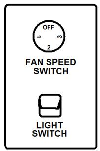
CONTENTS

GB   Installation Instruction Manual .......................................................................................... 3
D    Installationsanleitung ........................................................................................................13
F    Guide d’installation............................................................................................................23
E    Manual de instrucciones de instalación.............................................................................33
I    Manuale delle istruzioni di installazione............................................................................43
NL   Installatiehandleiding.........................................................................................................53

                                                                 2
CONGRATULATIONS ON YOUR PURCHASE
Congratulations on purchasing this quality Lucci product. To ensure correct function and
safety, please read and save all instructions carefully before using the product.
SAFETY PRECAUTIONS
The information contained in the following pages has been prepared to ensure you of
trouble-free operation of your Ceiling Fan .
1. This appliance is NOT intended for use by persons (including children) with reduced
physical, sensory or mental capabilities, or lack of experience and knowledge, unless they
have been given supervision or instruction concerning use of the appliance by a person
responsible for their safety.
2. The all-poles disconnection must be incorporated in the fixed wiring in accordance with
local wiring rules.
3. Do not dispose of electrical appliances as unsorted municipal waste, use separate
collection facilities. Contact your local government for information regarding the collection
systems available. If electrical appliances are disposed of in landfills or dumps, hazardous
substances can leak into the groundwater and get into the food chain, damaging your
health and well-being.
4. The structure to which the fan is to be mounted must be capable of supporting a weight of
30kg.
5. The fan should be mounted so that the blades are at least 2.3 meters above the floor in
Europe
6. The fan should be mounted so that the blades are at least 2.1 meters above the floor in
Australia
7. The fan is designed for indoor use only. Mounting the fan in a situation where it is subject
to water or moisture is dangerous.
8. Only an authorized electrician should execute the installation.
3BEFORE INSTALLATION
Unpack the fan and carefully identify the parts. Please refer to Fig 1.
Fig. 1
● Down rod with ball joint (1) x 1
● Fan motor assembly (2) x 1
● Canopy with hanger bracket (3) x 1
● Blade holders (4) x 5
● Blades (5) x 5
● Wall plugs for screws (6) x 2
● Wooden screws (7) x 2
● Bladed mounting screws (8) x 16
● Extra motor screw (9)x 1
● Balance kit (10)x 1 set
● Wall switch (11) x 1 set
NOTE:Some models do not include the light kit, please refer to technical information.
4INSTALLING THE MOUNTING BRACKET
The ceiling fan must be installed in a location so that the blades are 300mm spacing from the tip of
the blade to the nearest objects or walls.
Secure the hanging bracket to the ceiling joist or structure that is capable of carrying a load of at
least 30KG, with two long screws provided. Ensure at least 30mm of the screw is threaded into the
support.
Fig. 2
NOTE: The bracket screws provided are for use with wooden structures only. For structures
other than wood, the appropriate screw type MUST be used.
Angled Ceiling Installation
This fan hanging system supports a maximum 20
degree angled ceiling installation.
Fig. 3
5BLADE INSTALLATION
Install the down rod
1. Loose ball joint.
2. Feed down rod through ceiling canopy.
3. Insert the motor wires through down rod, and then secure
ball joint back to down rod.
4. Insert down rod to hanger (see Fig.4), line up hanger
holes with down rod holes and insert bolt. Then insert pin
to end of bolt.
5. Finally secure down rod and hanger via tightening two
screws on the hanger.
Fig. 4
Blade attachment
1. Before Installing the blades, remove the motor screws.
2. Assemble the blades & holders using the screw set. (Fig. 5)
3. Secure the blade on the motor by using 2 screws with washers to tighten it ensuring they are
tightened simultaneously. (Take care not to over tighten as this can damage blades) (Fig.6)
Once completed, repeat the process on remaining blades.
Fig. 6
Fig. 5
6HANGING THE FAN
INSTALLING THE FAN
Lift fan assembly onto mounting bracket.
Fig.7
Ensure the notch of the ball joint is
positioned on the stopper of mounting
bracket to prevent fan from rotating when in
operation.
Fig. 7
LIGHT KIT Installation (Light kit – optional )
Note: Light kit must be installed by a Licensed Electrician.
NOTE: The light kit is NOT included for selected ceiling fan models and as an optional light kit.
Fig. 8 Fig. 9
1. Take off the light housing cover from light housing via loosening the light housing screws(Fig.8)
2. Push the decorative cover out from light housing cover.
3. Insert the L and N light wires through the hole of light housing cover. (Fig.9)
4. Tighten the fan light kit to light housing cover firmly. Secure light kit to light housing cover via a
screw nut and washer.
5. Connect the L and N light wires to terminal block inside fan light housing properly.
6. Secure the fan light housing cover back to light housing by 3 screws.
7. Install bulbs with bulb changer, and then turn on the power.
7ELECTRICAL WIRING DIAGRAM
INSTALLING
WARNING: FOR YOUR SAFETY ALL ELECTRICALTHE FAN
CONNECTIONS MUST BE UNDERTAKEN BY
A LICENSED ELECTRICIAN.
NOTE: AN ADDITIONAL ALL POLE DISCONNECTION SWITCH MUST BE INCLUDED IN THE
FIXED WIRING.
Fig. 10
NOTE: Wiring diagram includes the light kit wiring. The light wiring diagram and switch is
omitted when no light kit is use with the ceiling fan.
Fig. 11
Rotary switch and capacitor wiring diagram.
8FINISHING THE INSTALLATION
After completing the electrical connection at the mounting bracket terminal block, connect the
ceiling fan wiring via the quick connector plug.
Cover the mounting bracket with the canopy. Ensure all electrical wiring is tucked inside the
canopy and that they are not damaged during this step. Secure the canopy to the hanger bracket
using the screws provided. Fig 10.
Fig. 12
9USING YOUR CEILING FAN
FAN WALL CONTROL
Your ceiling fan is controlled via the rotary switch (fan) and rocker switch (light) via the wall controller. Refer to
below figures:
SWITCH POSITION
DESCRIPTION
(ARROW POINTING)
OFF – FAN IS OFF
1 – FAN IS “ON”, SPEED = HIGH
2 – FAN IS “ON”, SPEED = MEDIUM
3 – FAN IS “ON”, SPEED = LOW
LIGHT SWITCH – Toggle to switch ON/OFF the light
WALL CONTROLLER
Fig. 13
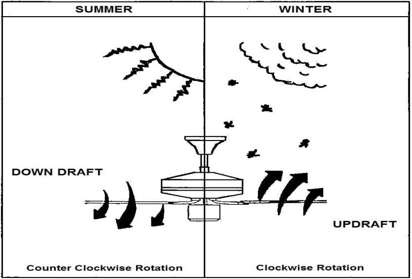
10REVERSING SWITCH
Your ceiling can operate either summer or winter mode.
SUMMER Mode: The reverse switch shall be in the “down” (SUMMER) position to make the fan
rotate in an anticlockwise direction. The airflow will be directed downwards, for cooling in summer.
WINTER Mode: The reverse switch shall be in the “up” (WINTER) position to make the fan rotate in a
clockwise direction. The airflow will be directed upwards assisting in the circulation of warm air, for
energy conservation in winter.
Reverse Switch Fig. 14
AFTER INSTALLATION
WOBBLE:
NOTE: CEILING FANS TEND TO MOVE DURING OPERATION DUE TO THE FACT THAT THEY
ARE MOUNTED ON A RUBBER GROMMET. IF THE FAN WAS MOUNTED RIGIDLY TO THE
CEILING IT WOULD CAUSE EXCESSIVE VIBRATION. MOVEMENT OF A FEW CENTIMETRES IS
QUITE ACCEPTABLE AND DOES NOT SUGGEST ANY PROBLEM.
TO REDUCE THE FAN WOBBLE: PLEASE CHECK THAT ALL SCREWS WHICH FIX THE
MOUNTING BRACKET AND DOWN ROD ARE SECURE.
BALANCING KIT: A balancing kit is provided to balance the ceiling fan on initial installation. Please
refer to the instruction on how to use the balancing kit. The balancing kit can be used to assist
re-balancing should the ceiling fan become un-balanced again. Store your balancing kit away after
installation for future use if required.
NOISE:
When it is quiet (especially at night) you may hear occasional small noises. Slight power fluctuations
11and frequency signals superimposed in the electricity for off-peak hot water control, may cause a
change in fan motor noise. This is normal. Please allow a 24-hour “breaking -in” period, most noises
associated with a new fan disappear during the time. The manufacturer’s warranty covers actual faults
that may develop and NOT minor complaints such as hearing the motor run – All electric motors are
audible to some extent.
CARE AND CLEANING
Periodic cleaning of your ceiling fan is the only maintenance required. Use a soft brush or lint free
cloth to avoid scratching the paint finish. Please turn off electricity power when you do so.
Do not use water when cleaning your ceiling fan. It could damage the motor or the blades and
create the possibility of an electrical shock.
The motor has a permanently lubricated ball bearing. There is no need to oil
NOTE: Always turn off the power at the mains switch before attempting to clean your fan.
TECHNICAL INFORMATION
Rated Power Rated Power
Ceiling Fan model Rated Voltage
(motor) (lamp)
SKU#210294 220-240VAC 60W Light not included
LD-WHF188019/WH
SKU#210293 220-240VAC 60W Light not included
LD-WHF188019/BR
WARRANTY INFORMATION
IN AUSTRALIA / NEW ZEALAND CUSTOMER – Please refer to the separated WARRANTY
STATEMENT.
IN EUROPE – If you are a European Customer Please contact the retail outlet where the fan was
purchase for warranty service.
12WIR GRATULIEREN ZUM KAUF DIESES GERÄTES
Wir gratulieren zum Kauf dieses Qualitätsproduktes von Lucci. Bitte lesen Sie die
Sicherheitshinweise vollständig und sorgfältig durch, um den ordnungsgemäßen und sicheren
Einsatz des Gerätes zu gewährleisten.
SICHERHEITSHINWEISE
Die Hinweise auf den nachfolgenden Seiten erklären den sicheren und störungsfreien Betrieb
Ihres Deckenventilators.
1. Dieses Gerät ist NICHT für den Gebrauch durch Personen (einschließlich Kinder) geeignet,
die über eingeschränkte körperliche, sensorische oder mentale Fähigkeiten oder über
mangelnde Erfahrung und Kenntnisse verfügen, es sei denn, ihr Gebrauch des Gerätes
wird durch eine Person, die für deren Sicherheit verantwortlich ist, entsprechend
beaufsichtigt oder angeleitet.
2. Laut Schutzvorschrift muss bei der Festverdrahtung die allpolige Trennung verwendet
werden.
3. Bedeutung des durchgestrichenen Müllbehälters auf Rollen: Geben Sie elektrische Geräte
nicht in den Hausmüll (Restmüll), sondern achten Sie auf umweltgerechte Entsorgung.
Falls Sie sich hierzu nicht sicher sind, erkundigen Sie sich bei Ihrer örtlichen Behörde nach
den sachgerechten Entsorgungsmöglichkeiten. Elektrische Geräte, die auf eine Müllhalde
geworfen werden, können Gefahrstoffe in das Grundwasser abgeben, die in die
Nahrungskette gelangen und dadurch gesundheitsschädlich sind.
4. Die Decke, an die dieser Ventilator befestigt werden soll, muss ein Gewicht von 30 kg
tragen können.
5. In Europa sollte der Ventilator so an der Decke befestigt werden, dass sich die
Ventilatorflügel mindestens 2,3m über dem Boden befinden.
6. In Australien sollte der Ventilator so an der Decke befestigt werden, dass sich die
Ventilatorflügel mindestens 2,1m über dem Boden befinden.
7. Der Ventilator ist ausschließlich für die Verwendung im Innenbereich konstruiert. Es ist
gefährlich, den Ventilator in Umgebungen zu installieren, in denen er Wasser oder
Feuchtigkeit ausgesetzt ist.
8. Die Installation sollte nur von einem befugten Elektriker vorgenommen werden.
13VOR DER INSTALLATION ZU BEACHTEN
Bitte packen Sie das Gerät aus, und stellen Sie sicher, dass alle Teile im Versandkarton enthalten sind.
Bitte beachten Sie Abb. 1.
Abb. 1
● Hängerohr mit Kugelgelenk (1) x 1
● Motorblock (2) x 1
● Canopy mit Deckenhalterung (3) x 1
● Flügelblätterbefestigungen (4) x 5
● Flügelblätter (5) x 5
● Wanddübel für Schrauben (6) x 2
● Holzschrauben (7) x 2
● Befestigungsschrauben für Flügelblätter (8) x 16
● Motorenersatzschrauben (9)x 1
● Balance Kit (10)x 1 Satz
● Wandschalter (11) x 1 Satz
HINWEIS:Nicht alle Modelle werden mit einem Leuchtensatz geliefert. Ausführlicheres darüber
finden Sie in den technischen Informationen.
14INSTALLATION DER DECKENHALTERUNG
Der Deckenventilator muss an einem Ort so installiert werden, dass die Spitzen der
Ventilatorflügel mindestens 300mm vom nächsten Gegenstand oder der Wand entfernt sind.
Befestigen Sie die Deckenhalterung nur an Decken oder Deckenverschalungen und anderen
Deckenstrukturen, die ein Gewicht von mindestens 30KG sicher halten können; verwenden Sie
dazu die zwei langen Schrauben, die mit dem Ventilator ausgeliefert wurden. Stellen Sie sicher,
dass die Schraubengewinde mindestens 30mm in das Material eingedreht sind, woran die
Halterung für den Ventilator befestigt ist.
Abb. 2
HINWEIS: Die mitgelieferten Halteschrauben sind nur für Tragestrukturen aus Holz geeignet.
Für Tragestrukturen die nicht aus Holz sind, MUSS der dafür geeignete und zugelassene
Schraubentyp verwendet werden.
Installation an geneigten Decken
Dieses Halterungssystem ist nur für die
Aufhängung an geneigten Decken mit einem
Neigungswinkel von bis zu 20 geeignet.
Abb. 3
15VENTILATORFLÜGEL - INSTALLATION
Montage des Hängerohrs
1. Kugelgelenk lockern.
2. Das Hängerohr durch die Deckenhalterung führen.
3. Den Kabelstrang des Motors in das Hängerohr schieben
und das Kugelgelenk wieder am Hängerohr befestigen
4. Das Hängerohr in die Aufhängestange schieben ( siehe
Abb.4) die Löcher der Aufhängestange auf die Löcher des
Hängerohrs ausrichten und Bolzen einsetzen.
Anschließend den Stift bis zum Ende des Bolzen
einschieben.
5. Abschließend durch Festziehen der zwei Schrauben der
Aufhängestange das Hängerohr und die Aufhängestange sichern.
Abb. 4
Anbringen der Ventilatorflügel
1. Vor der Installation der Ventilatorflügel sollten Sie die Schrauben am Motor entfernen.
2. Bringen Sie die Ventilatorflügel & die Halterung an, indem Sie den mitgelieferten Schraubensatz
verwenden.
3. Sichern Sie die Flügel am Motor mittels 2 Schrauben mit Beilagscheiben, und achten Sie beim
Eindrehen der Schrauben darauf, dass diese gleich fest angezogen werden. (Überdrehen Sie die
Schrauben nicht, da dadurch die Ventilatorflügel beschädigt werden könnten.)
Wiederholen Sie den Vorgang für alle verbleibenden Ventilatorflügel.
Abb. 5 Abb. 6
16AUFHÄNGEN DES VENTILATORS
INSTALLING THE FAN
Setzen Sie die vormontierte Haltestange
an die Halterung an. Abb. 7
Stellen Sie sicher, dass die Nut am
Kugelgelenk in die Verdrehsicherung
eingeführt ist, um zu verhindern dass sich
der Ventilator während des Betriebs dreht.
Abb. 7
Montage des BELEUCHTUNGSSATZES (Beleuchtungssatz – optional )
Hinweis: Der Einbau des Beleuchtungssatzes ist von einem erfahrenen Elektrofachmann
auszuführen.
HINWEIS: Der Beleuchtungssatz ist im Lieferumfang bestimmter Ventilatormodelle NICHT inbegriffen
und wird nur auf Wunsch geliefert.
Abb. 9
Abb. 8
1. Die Schrauben des Beleuchtungsgehäuses lockern und Gehäuseabdeckung entfernen (Abb.8)
2. Die dekorative Abdeckung aus dem Beleuchtungsgehäuse herausdrücken.
3. Die L und N Beleuchtungskabel durch die Öffnung des Beleuchtungsgehäuses einschieben
(Abb.9)
4. Den Beleuchtungssatz des Ventilators fest auf dem Beleuchtungsgehäuse anbringen.
Beleuchtungssatz durch Festziehen der Schraubenmutter mit Unterlegscheibe sichern.
5. Die L und N Kabel ordnungsgemäss an die Klemme im Inneren des Beleuchtungsgehäuses
anschließen.
6. Die Abdeckung des Beleuchtungsgeghäuses mit 3 Schrauben wieder befestigen.
7. Glühbirnen einschrauben und Strom einschalten.
17ELEKTRISCHE VERSCHALTUNG - DIAGRAMM
WARNHINWEIS: INSTALLING
IM INTERESSE THE FAN SICHERHEIT
IHRER PERSÖNLICHEN MÜSSEN ALLE
ELEKTRISCHEN ANSCHÜSSE VON EINEM ZUGELASSENEN ELEKTRIKER AUSGEFÜHRT
WERDEN.
HINWEIS: EIN ZUSÄTZLICHER, ALLPOLIGER TRENNSCHATER MUSS IN DER INSTALLATION
DER WANDVERKABELUNG ENTHALTEN SEIN.
Abb. 10
HINWEIS: Das Verkabelungsdiagramm zeigt die Verschaltung des Kabelsatzes für die den
Schalter und das Licht. Das Verkabelungsdiagramm für das Licht und den Schalter werden
nicht dargestellt, wenn Ihr Deckenventilator nicht mit einer Lampe ausgerüstet ist.
Abb. 11
Verschaltungsdiagramm für Drehschalter und Regelungskondensator.
18ABSCHLUSS DER INSTALLATION
Nach Abschluss der elektrischen Anschlüsse am Kabelblock der Halterung schließen Sie die
Verkabelung des den Deckenventilator über den Verbindungsstecker an der
Netzstromversorgung an.
Decken Sie die Halterung mit der Abdeckung ab. Die Verkabelung befindet sich nun unter der
Abdeckung und Sie sollten darauf achten, dass diese in diesem Schritt nicht beschädigt wird.
Sichern Sie die Abdeckung an der Halterung der Deckenstange mittels der mitgelieferten
Schrauben. Abb. 12
Abb. 12
19DER EINSATZ DES DECKENVENTILATORS
VENTILATOR WANDREGLER
Sie können die Geschwindigkeit Ihres Deckenventilators über den Drehschalter (Ventilator) regeln, und das Licht
mittels des Kippschalters (Licht) ein- und ausschalten. Beachten Sie die nachfolgende Abbildung:
SCHALTERSTELLUNG
BESCHREIBUNG
(PFEILRICHTUNG)
AUS – VENTILATOR IST AUS
1 – VENTILATOR IST “EIN”, GESCHWINDIGKEIT = HOCH
2 – VENTILATOR IST “EIN”, GESCHWINDIGKEIT = MITTEL
3 – VENTILATOR IST “EIN”, GESCHWINDIGKEIT = NIEDRIG
LICHTSCHALTER – Betätigen, um Licht EIN/AUS zu schalten.
WANDREGLER
Abb. 13
20RÜCKLAUFFUNKTION
Der Ventilator kann sowohl im Vorlauf als auch im Rücklauf betrieben werden.
SOMMERBETRIEB: Wenn der Schalter für die Rücklauffunktion auf “down” (SOMMER) steht, dreht
der Ventilator sich gegen den Uhrzeigersinn. Die Luftbewegung wird nach unten gelenkt und bringt im
Sommer den gewünschten Abkühlungseffekt.
WINTERBETRIEB: Wenn der Schalter für die Rücklauffunktion auf “up” (WINTER) steht, dreht sich
der Ventilator im Uhrzeigersinn. Die Luftbewegung wird nach oben gelenkt, um im Winter Energie zu
sparen.
Reverse Switch Abb. 14
NACH DER INSTALLATION
WACKELN
Die Flügelblätter des Ventilators wurden ab Werk angepasst, um ein Wackeln möglichst zu
vermeiden.
HINWEIS: DA DECKENVENTILATOREN AN EINER GUMMI-ISOLIERSCHEIBE MONTIERT SIND,
TENDIEREN SIE DAZU, WäHREND DES BETRIEBS IN BEWEGUNG ZU SEIN. FALLS DER
VENTILATOR ZU FEST AN DER DECKE BEFESTIGT WIRD, KANN DIES ZU ÜBERMäSSIGER
VIBRATION FÜHREN. MEHRERE ZENTIMETER BEWEGUNGSSPIELRAUM SIND AKZEPTABEL
UND STELLEN KEIN PROBLEM DAR.
REDUZIEREN VON WACKELN: ÜBERPRÜFEN SIE, OB ALLE SCHRAUBEN DER
BEFESTIGUNGSPLATTEN UND DES HäNGEROHRS FEST SITZEN.
GERÄUSCHE
In einer geräuscharmen Umgebung kann es gelegentlich (vor allem nachts) vorkommen, dass leise
Geräusche des Ventilators zu vernehmen sind. Das Geräusch des Ventilatormotors kann sich durch
geringe Stromschwankungen und Abweichungen in der Stromfrequenz ändern. Das ist völlig normal.
Die meisten Geräusche eines neuen Ventilators verschwinden nach einer „Eingewöhnungszeit“ von
etwa 24 Stunden. Die Garantie des Herstellers erstreckt sich auf tatsächliche Fehler, die u. U.
auftreten können, und NICHT auf geringfügige Beschwerden wie zum Beispiel hörbare
21Motorgeräusche. Jeder Elektromotor ist in gewissem Umfang hörbar.
REINIGUNGS- UND PFLEGEHINWEISE
Außer gelegentlicher Reinigung bedarf dieser Ventilator keiner Wartung. Verwenden Sie hierfür
eine weiche Bürste oder einen fusselfreien Lappen, damit die Oberfläche nicht verkratzt wird. Der
Ventilator sollte zur Reinigung ausgeschaltet werden.
Den Ventilator nicht mit Wasser reinigen. Wasser kann den Motor oder die Flügelblätter
beschädigen und zu Stromschlägen führen.
Der Motor hat dauergeschmierte Kugellager. Er muss nicht geölt werden.
HINWEIS: Unterbrechen Sie die Stromzufuhr, bevor der Ventilator gereinigt wird.
TECHNISCHE DATEN
Deckenventilator Betriebsspannung Betriebsspannung
Betriebsspannung
Modell (Motor) (Lampe)
SKU#210294 220-240VAC 60W Ohne Beleuchtung
LD-WHF188019/WH
SKU#210293 220-240VAC 60W Ohne Beleuchtung
LD-WHF188019/BR
WARRANTY INFORMATION
IN AUSTRALIA / NEW ZEALAND CUSTOMER – Please refer to the separated WARRANTY
STATEMENT.
IN EUROPA – Falls Sie ein Kunde in Europa sind, dann treten Sie für eventuelle Garantieleistungen
bitte mit dem Fachgeschäft in Kontakt, bei dem Sie den Ventilator gekauft haben.
22MERCI POUR VOTRE ACQUISITION
Merci d’avoir acheté ce produit de qualité de LUCCI. Pour garantiser la securité et le
fonctionnement correct, lire et sauver soigneusement tous les instructions avant d’utiliser le
produit.
PRECAUTIONS à PRENDRE
L’information que les pages suivantes contiennent a été préparée pour assurer l’operation
rapide de votre ventilateur au plafond.
1. Cet appareil N’est PAS destiné à être utilisé par des personnes (y compris des enfants)
avec des capacités physiques, sensorielles ou mentales limitées, ou un manque
d’expérience et de connaissances, à moins qu’ils ne bénéficient de la supervision ou qu’il
ne leur ait été dispensé des instructions concernant l’utilisation de l’appareil par une
personne responsable de leur sécurité.
2. La déconnexion tous pôles doit être intégrée au câblage fixe conformément aux règles de
câblage.
3. Signification de l’icône « Poubelle à roulettes barrée » Ne pas jeter les appareils
électriques avec les déchets municipaux non-triés ; utilisez des installations de ramassage
séparées. Contactez votre mairie pour obtenir des informations relatives aux systèmes de
ramassage disponibles. Si les appareils électriques sont jetés dans des décharges
sauvages ou publiques, des substances dangereuses peuvent pénétrer dans la nappe
phréatique ainsi que dans la chaîne alimentaire, et nuire à votre santé et votre bien-être.
4. La structure dans laquelle le ventilateur doit être monté doit pouvoir supporter un poids de
30kg.
5. Le ventilateur doit être installé de manière à ce que les pâles soient au moins à 2,3 mètres
au dessus du sol en Europe.
6. Le ventilateur doit être installé de manière à ce que les pâles soient au moins à 2,1 mètres
au dessus du sol en Australie.
7. Le ventilateur et conçu pour utilisation en intérieur uniquement. Monter le ventilateur dans
un environnement où il est exposé à l’eau ou à l’humidité est dangereux.
8. Le ventilateur doit être installé uniquement par un électricien qualifié.
23AVANT L’INSTALLATION
Déballer le ventilateur et identifier les pièces avec prudence. Veuillez référer à Fig 1.
Fig. 1
● Tige de bas avec un joint sphérique (1) x 1
● Assemblage du moteur de ventilateur (2) x 1
● Auvent avec support de suspension (3) x 1
● Supports de lame (4) x 5
● Lames (5) x 5
● Prises murales de vis (6) x 2
● Vis en bois (7) x 2
● Vis de montage en lamelle (8) x 16
● Vis de moteur supplémentaire (9) x 1
● Kits d’équilibrage (10) x 1 jeu
● Commutateur mural (11) x 1 jeu
REMARQUE:Certains modèles ne contiennent pas le kit d’éclairage, veuillez référer à
l’information technique.
24INSTALLATION DE SUPPORT DE FIXATION
Le ventilateur doit être installé dans une position où les pales sont 300mm en espace de chaque
point de pale même au mur le plus proche.
Assurer le support de suspension à la solive de plafond ou structure qui est capable de
transporter une charge de 30KG au moins avec l’utilisation de deux vis longues. Assurer qu’au
moins 30mm de vis soit inséré au support.
Fig. 2
REMARQUE: Les vis de support doivent être seulement utilisées sur les structures à bois.
Autre que les bois, il FAUT utiliser la vis correcte pour les autres structures.
Installation au Plafond Incliné
Ce système de suspension du ventilateur
transporte au maximum 20 degré de plafond
incliné.
Fig. 3
25INSTALLATION DE PALE
Installer la tige de bas
1. Desserez le joint sphérique
2. Insérez la tige de bas à travers l’auvent du plafond
3. Insérez les câbles de moteurs à travers la tige de bas et
puis fixez à nouveau le joint sphérique à la tige de bas.
4. Insérez la tige de bas au support (voir Fig 4), alignez les
trous de suspension avec les trous de tige de bas et insérez
le boulon. Puis insérez la broche à l’extrémité du boulon.
5. Fixez finalement la tige de bas et le support en serrant deux
vis sur le support de suspension.
Fig. 4
Installation de pale
1. Avant d’installer les pales, enlever les moteurs à vis.
2. Assembler les pales et les porte-lames en utilisant les vis.
3. Assurer les pales sur le moteur en utilisant 2 vis avec des rondelles pour les serrer en s’assurant
qu’ils sont bien serrés simultanément. (Veillez à ne pas trop serrer car cela peut endommager les
pales.)
Lorsqu’il est complété, répéter la procédure sur les pales restantes.
Fig. 6
Fig. 5
26PENDAISON DU VENTILATEUR
INSTALLING THE FAN
Enlever l’assemblage de ventilateur au
support de montage Fig.7
Assurer que l’entaille de la rotule soit
positionnée au bouchon du support de
montage pour empêcher l’oscillation de
ventilateur en fonctionnement.
Fig. 7
Installation du KIT D’ÉCLAIRAGE (Kit d’éclairage – optionnel)
Remarque : Le kit d’éclairage doit être installé par un Électricien Agréé.
REMARQUE : Le kit d’éclairage N’est PAS inclus pour les modèles de ventilateur de plafond
sélectionné et comme un kit d'éclairage optionnel.
Fig. 8 Fig. 9
1. Enlevez le couvercle du boîtier d’éclairage du boîtier d’éclairage en desserrant les vis du boîtier
d’éclairage (Fig 8)
2. Poussez le couvercle décoratif vers l’extérieur du couvercle du boîtier d’éclairage.
3. Insérez les câbles d’éclairage L et N à travers le trou du couvercle du boîtier d’éclairage. (Fig 9)
4. Serrez fermement le kit d’éclairage de ventilateur vers le couvercle du boîtier d’éclairage. Fixez le
kit d’éclairage au couvercle du boîtier d’éclairage à l’aide d’une vis-et-écrou et une rondelle.
5. Connectez convenablement les câbles d’éclairage L et N au bloc terminal à l’intérieur du boîtier
d’éclairage du ventilateur.
6. Fixez à nouveau le couvercle du boîtier d’éclairage du ventilateur au boîtier d’éclairage à l’aide de 3
vis.
7. Installez les ampoules avec un changeur d’ampoule et puis mettez sous tension.
27PLAN DE CÂBLAGE ÉLECTRIQUE
INSTALLING THE FAN
AVERTISSEMENT: POUR VOTRE SÉCURITÉ, IL FAUT CONTACTER UN ELECTRICIAN
AUTHORISÉ POUR TOUS LES CONNEXIONS ELECTRIQUES.
REMARQUE: Il FAUT AVOIR UNE INTERRUPTEUR À COUPURE OMNIPOLAIRE DANS LE
CÂBLAGE FIXÉ.
Fig. 10
REMARQUE: Il est inclus au plan de câblage le kit de câblage à lumière. Le plan de câblage à
lumière et l’interrupteur sont éteints lorsqu’il n y a pas de lumière activée pour le ventilateur.
Fig. 11
Interrupteur rotatif and condensateur du plan de câblage.
28COMPLÈTEMENT DE L’INSTALLATION
Après avoir complété la connexion électrique au bornier du support de montage, connecter le
câblage de ventilateur au plafond en utilisant le connecteur libre.
Couvrir le support de montage avec la voile. Assurer que tous les câblages électriques soient
dans la voile et qui ne soient pas endommagés pendant cette procédure. Assurer la voile au
support de suspension en utilisant les vis. Fig 10.
Fig. 12
29UTILISER VOTRE VENTILATEUR AU PLAFOND
Contrôle de ventilateur au mur
Votre ventilateur est contrôlé à l’aide de l’interrupteur rotatif (ventilateur) et le contact basculant (lumière) à l’aide
du contrôleur de mur. Veuillez référer les figures de sous:
POSITION de L’INTERRUPTEUR
DESCRIPTION
(La Pointe de Flèche)
éteint – le ventilateur est éteint
1 – le ventilateur est “ALLUMÉ”, VITESSE = HAUTE
2 – le ventilateur est “ALLUMÉ”, VITESSE = MOYENNE
3 – le ventilateur est “ALLUMÉ”, VITESSE = BASE
INTERRUPTEUR de LUMIÈRE – Basculer la lumière
Contrôleur de mur
Fig. 13
30FONCTIONNEMENT INVERSÉ
Votre ventilateur peut être opéré en mode ventilateur et en mode ventilateur inversé.
Mode ÉTÉ: Positionner l'interrupteur inverseur sur “down” (SUMMER) afin de faire tourner le
ventilateur dans le sens inverse des aiguilles du montre. Le jet d'air orienté vers le bas crée un courant
d'air frais.
Mode HIVER: Positionner l'interrupteur inverseur sur “up” (WINTER) afin de faire tourner le ventilateur
dans le sens des aiguilles d'une montre. La répartition de l'air ambiant chauffé vers le haut favorise les
économies d'énergie.
Reverse Switch Fig. 14
APRÈS L’INSTALLATION
OSCILLATION
Les pales du ventilateur ont été réglées en usine pour minimiser le phénomène d’oscillation.
REMARQUE : LES VENTILATEURS DE PLAFOND ONT TENDANCE À BOUGER EN
FONCTIONNEMENT DU FAIT QU’ILS SONT MONTÉS SUR UNE BAGUE EN CAOUTCHOUC. SI
LE VENTILATEUR ÉTAIT MONTÉ DIRECTEMENT SUR LE PLAFOND IL OCCASIONNERAIT DES
VIBRATIONS EXCESSIVES. UN MOUVEMENT DE QUELQUES CENTIMÈTRES EST
RELATIVEMENT ACCEPTABLE ET N’INDIQUE PAS UN PROBLÈME.
POUR RÉDUIRE L’OSCILLATION DU VENTILATEUR : VEUILLEZ VOUS ASSURER QUE TOUTES
LES VIS DE FIXATION DU SUPPORT DE MONTAGE ET DE LA TIGE DE SUSPENSION SONT
BIEN SERRÉES.
BRUIT :
Lorsque tout est tranquille (tout spécialement la nuit) il se peut que vous entendiez des bruits
occasionnels. De légères fluctuations de réseau et des signaux de fréquences superposées aux
dispositifs de contrôle de l’alimentation en électricité peuvent occasionner un changement au niveau
du bruit du moteur. Cela est normal. Après une période de “rodage” de 24 heures, la plupart des bruits
associés à un nouveau ventilateur disparaîtront. La garantie du fabricant couvre tous les défauts réels
31qui peuvent survenir et NON PAS des réclamations mineures telles que le fait d’entendre le moteur
tourner – Tous les moteurs électriques émettent un certain niveau de bruit audible.
NETTOYAGE ET ENTRETIEN
Le nettoyage périodique de votre ventilateur de plafond est le seul entretien requis. Utilisez
uniquement une brosse à poils doux ou un chiffon non pelucheux afin d’éviter d’égratigner la
finition. Veuillez couper l’électricité lorsque vous procédez à cette opération.
Ne nettoyez pas votre ventilateur de plafond avec de l’eau. Cela pourrait endommager le
moteur ou les pales et poser un risque de choc électrique.
Le moteur est équipé de roulements à billes lubrifiés à vie. Il n’est pas nécessaire de les
graisser.
REMARQUE : Veillez à toujours débrancher l’électricité de tenter de nettoyer votre ventilateur.
INFORMATION TECHNIQUE
Puissance
Tension Puissance Assignée
Modèle de Ventilateur Assignée
Assignée (lampe)
(moteur)
SKU#210294 220 - 240V c.a.• 60W Éclairage non inclus
LD-WHF188019/WH
SKU#210293 220 - 240V c.a.• 60W Éclairage non inclus
LD-WHF188019/BR
WARRANTY INFORMATION
IN AUSTRALIA / NEW ZEALAND CUSTOMER – Please refer to the separated WARRANTY
STATEMENT.
EN EUROPE – Si vous êtes un consommateur Européen, veuillez contacter le point de vente ou vous
avez acheté le ventilateur pour faire valoir la garantie.
32FELICITACIONES POR SU COMPRA
Felicitaciones por la compra de este producto de calidad de Lucci. Para garantizar el
funcionamiento y seguridad, por favor antes de utilizar el producto, lea detalladamente todas
las instrucciones y guárdelas para futura referencia.
PRECAUCIONES DE SEGURIDAD
La información contenida en las páginas siguientes ha sido preparada para asegurar el
funcionamiento libre de problemas de su ventilador de techo.
1. Este aparato NO ha sido diseñado para ser utilizado por personas (incluidos niños) con
capacidades físicas, sensoriales o mentales disminuidas, o falta de experiencia o
conocimiento, a menos que haya una persona responsable de su seguridad que los
supervise o brinde instrucción respecto al uso del dispositivo.
2. Conforme a las normas de cableado, se debe incorporar en todos los cableados fijos un
medio que permita desconectar todos los polos.
3. Significado del contenedor de basura con ruedas tachado: No deseche los aparatos
eléctricos como basura municipal no clasificada; utilice dispositivos de recolección
específicos. Póngase en contacto con el gobierno local para obtener información sobre los
sistemas de recolección disponibles. Al desechar los aparatos eléctricos en rellenos
sanitarios o vertederos, las sustancias peligrosas que contienen se pueden filtrar a las
aguas subterráneas e introducirse en la cadena alimentaria, lo que resulta prejudicial para
su salud y bienestar.
4. La estructura en la que se instale el ventilador debe poder soportar un peso de 30 kg.
5. En Europa, el ventilador deberá montarse de forma que las aspas estén por lo menos a una
altura de 2,3 metros sobre el suelo.
6. En Australia, el ventilador deberá montarse de forma que las aspas estén por lo menos a
una altura de 2,1 metros sobre el suelo.
7. El ventilador está diseñado para uso en interiores únicamente. Es peligroso instalar el
ventilador en un lugar adonde esté expuesto al agua o a la humedad.
8. La instalación sólo la puede hacer un electricista calificado.
33ANTES DE INSTALAR
Desempaque el ventilador e identifique las piezas cuidadosamente. Por favor, referirse a la figura 1.
Fig. 1
● Varilla vertical con junta de rotula (1) x 1
● Módulo de motor de ventilador (2) x 1
● Dosel con soporte de suspensión (3) x 1
● Soportes de aspas (4) x 5
● Aspas (5) x 5
● Tacos de pared para tornillos (6) x 2
● Tornillos para madera (7) x 2
● Tornillos de montaje para aspas (8) x 16
● Tornillos para motor adicionales (9)x 1
● Juego de oscilación (10)x 1 set
● Interruptor de pared (11) x 1 set
NOTA:Algunos modelos no incluyen el kit de luces, Por favor refiérase a la información
técnica.
34INSTALAR EL SOPORTE DE MONTAJE
El ventilador deberá instalarse en una ubicación de forma que las aspas está alejadas a una
distancia de 300mm desde el extreme del aspa al objeto mas cercano o paredes.
Asegure el soporte de suspensión a la viga de techo o estructura capaz de soportar una carga de
al menos 30Kg con los dos tornillos largos suministrados. Asegúrese de que el tornillo está
roscado al menos 30mm dentro del soporte.
Fig. 2
NOTA: Los tornillos del soporte suministrados son solo para utilizarse en estructuras de
madera. Para otras estructuras que no sean madera, DEBERÁN utilizarse el tipo de tornillos
adecuados.
Instalación en techos inclinados
Este sistema de ventilador colgante soporta un
máximo de 20 grados en instalaciones de techo
inclinado.
Fig. 3
35INSTALACIÓN DE LAS ASPAS
Instalar la varilla vertical
1. Afloje la junta esferica.
2. Inserte la varilla vertical a traves del dosel de techo.
3. Inserte los cable del motor a traves de la varilla vertical y
seguidamente vuelva a asegurar la junta esférica a la
varilla vertical.
4. Inserte la varilla vertical en el enganche (ver Fig.4), alinee
los agujeros de enganche con los agueros de la varilla
vertilcal e inserte el perno. Seguidamente inserte el
pasador en el extremo del perno.
5. Finalmente asegure la varilla vertical y el enganche
ajustando dos tornillos en el enganche.
Fig. 4
Instalación de las aspas
1. Antes de instalar las aspas, retire los tornillos del motor.
2. Ensamble las aspas y los soportes utilizando el juego de tornillos.
3. Asegure firmemente el aspa al motor utilizando 2 tornillos con arandelas, cerciorándose de de
están asegurados simultáneamente (Tenga cuidado de no apretar demasiado pues esto podría
dañar las aspas)
Una vez finalizado, repita el proceso con las aspas restantes.
Fig. 6
Fig. 5
36COLGAR EL VENTILADOR
INSTALLING THE FAN
.
Levante el modulo de ventilador sobre el
soporte de montaje. Fig.7
Asegúrese de que la muesca sobre la justa
esférica está colocada sobre el tope del
soporte de montaje para evitar que el
ventilador gire durante el funcionamiento.
Fig. 7
Instalación del JUEGO DE LUCES (Juego de luces – opcional)
Nota: El juego de luces deberá ser instalado por un Electricista Certificado.
NOTA: En determinados modelos el juego de luces NO está incluido, ni como juego de luces opcional.
Fig. 8 Fig. 9
1. Retire la tapadera de la caja de luces aflojando los tornillos (Fig.8)
2. Saque la cubierta decorativa de la tapadera de la caja de luces.
3. Inserte los cables de luces L y N a través del agujero de la caja de luces. (Fig.9)
4. Ajuste firmemente el juego de luces a la tapadera de la caja de luces. Asegure el juego de luces a
la tapadera utilizando un tornillo y arandela.
5. Conecte correctamente los cables de luces L y N al bloque de terminales dentro de la caja de
luces.
6. Vuelva a colocar la tapadera de la caja de luces y asegúrela utilizando 3 tornillos.
7. Instale las bombillas con el cambiador de bombillas, y conecte la corriente.
37DIAGRAMA DE CABLEADO ELÉCTRICO
ADVERTENCIA: INSTALLING
PARA SU SEGURIDAD THECONEXIONES
TODAS LAS FAN ELECTRICAS DEBERÁN
SER LLEVADAS A CABO POR UN ELECTRICISTA AUTORIZADO.
NOTA: DEBERÁ INCLUIRSE UN INTERRUPTOR OMNIPOLAR EN EL CABLEADO FIJO.
Fig. 10
NOTA: El diagrama de cableado incluye el cableado para juego de luces. Cuando el ventilador
no incluya luces, el diagrama de cableado de luces y el interruptor serán omitidos.
Fig. 11
Diagrama de cableado del interruptor giratorio y condensador.
38FINISHING THE INSTALLATION
Después de finalizar la conexión eléctrica en le bloque de terminales del soporte de montaje,
conecte el cableado del ventilador de techo a través del enchufe de conexión rápida.
Cubra el soporte de montaje con el dosel. Asegúrese de que todo el cableado eléctrico está
dentro del dosel y de que no ha sido dañado durante esta operación. Asegure el dosel al soporte
de suspensión utilizando los tornillos suministrados. Fig 10.
Fig. 12
39UTILIZAR SU VENTILADOR DE TECHO
MANDO DE PARED DEL VENTILADOR
Su ventilador de techo está controlador por un interruptor giratorio (ventilador) y un interruptor basculante (luz)
através del mando de pared. Ver las figuras a continuación:
POSICIÓN DEL INTERRUPTOR
DESCRIPCIÓN
(DIRECCIÓN DE LA FLECHA)
OFF – VENTILADOR APAGADO
1 – VENTILADOR ENCENDIDO, VELOCIDAD = MÁXIMA
2 – VENTILADOR ENCENDIDO, VELOCIDAD = MEDIA
3 – VENTILADOR ENCENDIDO, VELOCIDAD = MÍNIMA
INTERRUPTOR DE LUZ – Presionar para
ENCENDER/APAGAR la luz
MANDO DE PARED
Fig. 13
40Funcionamiento reversible
Su ventilador puede girar en dirección de reloj o en la contraria.
Modo VERANO: Si el interruptor para dirección del giro está hacia “abajo” (SUMMER) el ventilador
girará en dirección de reloj. El flujo de aire estará dirigido hacia abajo para enfriar con una brisa
directa.
Modo INVIERNO: Si el interruptor para dirección del giro está hacia “arriba” (WINTER) el ventilador
girará contra dirección de reloj. El flujo de aire estará dirigido hacia el techo para distribuir el aire
calido cerca del techo.
Reverse Switch Fig. 14
DESPUÉS DE LA INSTALACIÓN
OSCILACIÓN
Las paletas del ventilador han sido ajustadas en fábrica para minimizar toda oscilación.
NOTA: LOS VENTILADORES DE TECHO TIENDEN A MOVERSE DURANTE EL
FUNCIONAMIENTO DEBIDO A QUE ESTÁN MONTADOS A UNA ARANDELA DE CAUCHO. SI EL
VENTILADOR FUE MONTADO DIRECTAMENTE EN EL CIELO RASO, SE PRODUCIRÁ UN
EXCESO DE VIBRACIONES. UN MOVIMIENTO DE UNOS POCOS CENTÍMETROS ES
ACEPTABLE Y NO INDICA NINGÚN PROBLEMA.
PARA REDUCIR LA OSCILACIÓN DEL VENTILADOR: ASEGÚRESE DE QUE TODOS LOS
TORNILLOS UTILIZADOS PARA LA FIJACIÓN DEL SOPORTE DE MONTAJE Y LA VARILLA
VERTICAL ESTÉN AJUSTADOS.
RUIDO
Cuando esté silencioso (especialmente por la noche) es posible que escuche ocasionalmente algo de
ruido. Las pequeñas fluctuaciones de energía de la red y las señales de frecuencia que se
superponen en los dispositivos de control podrían ocasionar un cambio en el ruido del motor del
ventilador. Esto es normal. La mayoría de los ruidos asociados con un nuevo ventilador,
desaparecen después de que el ventilador ha funcionado durante un período de 24 horas. La garantía
del fabricante cubre todas las fallas reales que podrían presentarse y NO las quejas menores tales
como escuchar el ruido del motor - Todos los motores eléctricos generan un cierto nivel de ruido.
41LIMPIEZA Y CUIDADO
La limpieza periódica de su ventilador de techo es la única medida de mantenimiento necesaria.
Use un cepillo blando o un trapo sin pelusa para no rayar el acabado. Al hacerlo, desconecte la
alimentación eléctrica.
No limpie su ventilador de techo con agua. Esto podría dañar el motor o las paletas y generar un
riesgo de descarga eléctrica.
El motor tiene cojinetes de bolas de lubricación permanente. No es necesario aceitar el
ventilador.
NOTA: Antes de limpiar el ventilador, corte siempre el suministro de energía y desconecte el conector
hembra.
INFORMACIÓN TÉCNICA
Potencia
Modelo de Ventilador de Potencia Nominal
Tensión Nominal Nominal
Techo (bombilla)
(motor)
SKU#210294 220-240VAC 60W No incluye luces
LD-WHF188019/WH
SKU#210293 220-240VAC 60W No incluye luces
LD-WHF188019/BR
WARRANTY INFORMATION
IN AUSTRALIA / NEW ZEALAND CUSTOMER – Please refer to the separated WARRANTY
STATEMENT.
EN EUROPA – Si usted es un Cliente europeo, por favor póngase en contacto con el comercio donde
adquirió el ventilador para el servicio de garantia.
.
42CONGRATULAZIONI PER L'ACQUISTO
Congratulazioni per l'acquisto di questo prodotto di qualità Lucci. Per assicurare la corretta
funzionalità e la sicurezza, si prega di leggere con attenzione e salvare tutte le istruzioni prima
di utilizzare il prodotto.
PRECAUZIONI DI SICUREZZA
Le informazioni contenute nelle pagine seguenti sono state preparate per assicurare un
funzionamento senza problemi del ventiolatore a soffitto.
1. Questa unità NON è intesa per l’uso da parte di persone (e bambini) con ridotte capacità
fisiche, sensoriali o mentali e inesperte, a meno che non siano sorvegliate o abbiano
ricevuto le istruzioni sull’uso dell’unità da un responsabile della sicurezza.
2. Il dispositivo di scollegamento di tutti i poli deve essere integrato nel cablaggio fisso in
ottemperanza con le normative vigenti per il cablaggio.
3. Significato del bidone sbarrato: non smaltire gli elettrodomestici tra i rifiuti municipali
generici, ma utilizzare le campane della raccolta differenziata. Rivolgersi all’ente locale
preposto per informazioni sul sistema di raccolta differenziata. Elettrodomestici smaltiti
presso discariche pubbliche possono perdere sostanze pericolose che, se assorbite dal
terreno e dalle falde acquifere possono finire nella catena alimentare, con conseguenze
dannose per la salute.
4. La struttura per il montaggio del ventilatore deve essere in grado di sopportare un peso di
30 kg.
5. Montare il ventilatore in modo che le pale siano ad almeno 2,3 metri da terra in Europa.
6. Montare il ventilatore in modo che le pale siano ad almeno 2,1 metri da terra in Australia.
7. Il ventilatore e inteso solo per uso interno. Il suo montaggio in una posizione esposta
all’acqua o all’umidita costituisce un pericolo.
8. Affidare l’installazione del ventilatore a un elettricista competente.
43PRIMA DELL'INSTALLAZIONE
Disimballare il ventilatore e identificare con attenzione le parti. Si prega di fare riferimento alla Fig. 1.
Fig. 1
● Barra discendente con giunto a sfera (1) x 1
● Assemblaggio motore ventilatore (2) x 1
● Calotta con staffa di sostegno (3) x 1
● Ferma pale (4) x 5
● Pale (5) x 5
● Tasselli da muro per viti (6) x 2
● Viti da legno (7) x 2
● Viti di montaggio palettate (8) x 16
● Vite da ferro extra (9)x 1
● Kit di equilibratura (10)x 1 gruppo
● Interruttore da parete (11) x 1 gruppo
NOTA:Alcuni modelli non includono l’attrezzo di luce, vi preghiamo di riferire all’informazione
tecnica.
44INSTALLAZIONE DELLA STAFFA DI MONTAGGIO
Il ventilatore deve essere installato in una posizione tale da avere uno spazio libero di 300 mm tra
la punta della pala e l'oggetto o parete più vicina.
Fissare la staffa di sostegno al travetto o altra struttura del soffitto che sia in grado di sostenere un
carico di almeno 30KG, con le due viti lunghe in dotazione. Assicurarsi di avvitare le viti per
almeno 30 mm nel supporto.
Fig. 2
NOTA: Le viti in dotazione per fissare la staffa sono destinate ad essere usate soltanto con
strutture in legno. In caso di strutture non in legno, è NECESSARIO utilizzare viti appropriate.
Installazione su soffitto inclinato
Questo ventilatore può essere installato con
un'inclinazione massima di 20° rispetto al soffitto.
Fig. 3
45INSTALLAZIONE DELLE PALE
Installazione della barra discendente
1. Allentare il giunto a sfera.
2. Fate passare l’asta discendente attraverso la calotta a
soffitto.
3. Inserite i cavi del motore all’interno dell’asta, e quindi
assicurate il giunto a sfera di nuovo al giunto a sfera.
4. Inserite la barra discendente alla staffa (vedere Fig.4),
allineate i fori della staffa con i fori della barra discendente
ed inserite i bulloni. Quindi inserite il perno all’estremità del
bullone.
5. Infine assicurate la barra discendente e la staffa stringendo
due viti sulla staffa.
Fig. 4
Installazione delle pale
1. Prima d’installare le pale, togliere la vite a motore.
2. Assemblare le pale e porta-lame utilizzando la vite d’attrezzo.
3. Assicurare le pale sul motore utilizzando 2 vite con rondella per serrarle assicurandosi che sono
tutte serrate contemporaneamente. (Essere più prudente a non serrare troppo perché può
causare danno alle pale)
Al momento che sia completo, ripetere la procedura per le pale che rimangono.
Fig. 6
Fig. 5
46APPENDERE IL VENTILATORE
INSTALLING THE FAN
Sollevare il corpo del ventilatore alla staffa
di montaggio. Fig.7
Assicurarsi che la tacca del giunto sia
posizionata sullo stopper della staffa di
montaggio per impedire al corpo del
ventilatore di ruotare durante il
funzionamento.
Fig. 7
Installazione KIT LUCE (Kit luce – opzionale ).
Nota: Il kit luce deve essere installato da un elettricista qualificato.
NOTA: Il kit luce NON è incluso per modelli di ventilatori da soffitto selezionati e come un kit luce
opzionale.
Fig. 8 Fig. 9
1. Togliete il coperchio dell’alloggiamento della luce dall’alloggiamento della luce allentando le viti
dell’alloggiamento della luce (Fig. 8)
2. Spingete il coperchio decorativo fuori dal coperchio dell’alloggiamento della luce.
3. Inserite i fili L ed N della luce attraverso il foro del coperchio dell’alloggiamento della luce. (Fig. 9)
4. Stringete fermamente il kit luce del ventilatore al coperchio dell’alloggiamento della luce.
Assicurate il kit luce al coperchio dell’alloggiamento della luce con una vite, dato e rondella.
5. Collegate correttamente i fili L ed N della luce al blocco terminale all’interno dell’alloggiamento
della luce del ventilatore.
6. Assicurate di nuovo il coperchio dell’alloggiamento della luce del ventilatore all’alloggiamento della
luce con 3 viti.
7. Installare le lampadine con il cambia lampadine, e quindi accendete.
47SCHEMA DI CABLAGGIO ELETTRICO
ATTENZIONE: PER RAGIONI DI INSTALLING THEI COLLEGAMENTI
SICUREZZA, TUTTI FAN ELETTRICI DEVONO
ESSERE EFFETTUATI DA UN ELETTRICISTA AUTORIZZATO.
NOTA: UN INTERRUTTORE DI DISCONNESSIONE ONNIPOLARE AGGIUNTIVO DEVE ESSERE
INCORPORATO NEL CABLAGGIO FISSO.
Fig. 10
NOTA: Lo schema di cablaggio include il cablaggio del kit luce. Lo schema di cablaggio
dell'illuminazione e il relativo interruttore sono omessi quando il ventilatore a soffitto non
utilizza illuminazione.
Fig. 11
Schema di cablaggio di selettore rotativo e condensatore.
48COMPLETAMENTO DELL'INSTALLAZIONE
Dopo aver completato il collegamento elettrico al blocco terminale della staffa di montaggio,
collegare il cavo del ventilatore a soffitto tramite il connettore rapido.
Coprire la staffa di montaggio con la calotta. Assicurarsi che tutti i cavi elettrici siano nascosti
all'interno della calotta e che non siano stati danneggiati durante questa operazione. Fissare la
calotta alla staffa di supporto utilizzando le viti in dotazione. Fig 10.
Fig. 12
49UTILIZZO DEL VENTILATORE A SOFFITTO
CONTROLLER A PARETE DEL VENTILATORE
Il ventilatore a soffitto è comandato tramite l'interruttore rotativo (ventilatore) e l'interruttore basculante (luce) del
controller a parete. Fare riferimento alle figure seguenti:
POSIZIONE INTERRUTTORE
DESCRIZIONE
(INDICAZIONE FRECCIA)
OFF – IL VENTILATORE È SPENTO
1 – IL VENTILATORE È ACCESO A VELOCITÀ ALTA
2 – IL VENTILATORE È ACCESO A VELOCITÀ MEDIA
3 – IL VENTILATORE È ACCESO A VELOCITÀ BASSA
INTERRUTTORE LUCE - Per accendere/spegnere la luce
CONTROLLER A PARETE
Fig. 13
50FUNZIONE DI RITORNO
Il ventilatore può essere azionato in senso orario e antiorario.
MODO ESTIVO: se l'interruttore della funzione di ritorno si trova su “down” (ESTATE), significa che
ventilatore gira in senso antiorario. In questo caso l'aria viene deviata in basso rinfrescando il locale in
estate.
MODO INVERNALE: se l'interruttore della funzione di ritorno si trova su “up” (ESTATE), significa che
ventilatore gira in senso orario. In questo caso l'aria viene deviata in alto allo scopo di risparmiare
energia in inverno.
Reverse Switch Fig. 14
DOPO L’INSTALLAZIONE
TRABALLAMENTO
Le pale del ventilatore sono state calibrate in fabbrica per ridurre al minimo il traballamento.
NOTA: I VENTILATORI A SOFFITTO TENDONO A MUOVERSI DURANTE IL FUNZIONAMENTO
POICHÉ SONO MONTATI SU UN OCCHIELLO DI GOMMA. SE SI MONTASSE IL VENTILATORE IN
MODO RIGIDO AL SOFFITTO, PROVOCHEREBBE UNA VIBRAZIONE ECCESSIVA. UN
MOVIMENTO DI POCHI CENTIMETRI È NORMALE E NON È SINTOMO DI UN PROBLEMA.
PER RIDURRE IL TRABALLAMENTO: VERIFICARE CHE TUTTE LE VITI SIANO SERRATE
SALDAMENTE SULLA STAFFA DI MONTAGGIO E SULL’ASTA DI SOSPENSIONE.
RUMORE
Il ventilatore può occasionalmente produrre rumori, avvertibili soprattutto nel silenzio della notte. Le
lievi fluttuazioni elettriche ed i segnali di frequenza sovraimposti nella corrente elettrica possono
provocare variazioni nel rumore prodotto dal motore del ventilatore. Questa condizione è normale.
Concedere al ventilatore un periodo di rodaggio di 24, la maggioranza dei rumori scompare in
quest’arco di tempo. La garanzia del produttore copre solamente i guasti effettivi che possono
presentarsi, NON le lamentele sul rumore prodotto dal motore. Tutti i motori elettrici producono rumori
udibili di una certa entità.
51CURA E PULIZIA
Il ventilatore a soffitto richiede solo una pulizia periodica. Utilizzare una spazzola a setole morbide
o un panno non lanoso per non graffiarne la superficie verniciata. Disattivare l’alimentazione
prima di pulirlo.
Non utilizzare l’acqua per pulire il ventilatore, poiché potrebbe danneggiare il motore o le pale e
costituire il pericolo di scosse elettriche.
Il motore è dotato di cuscinetti a sfere lubrificati in modo permanente e non necessitano di essere
ingrassati.
NOTA: spegnere sempre l’alimentazione prima di pulire il ventilatore.
INFORMAZIONI TECNICHE
Modello di
Tensione Potenza nominale Potenza nominale
ventilatore a
nominale (motore) (lampada)
soffitto
SKU#210294 220-240V CA 60W Luce non inclusa
LD-WHF188019/WH
SKU#210293 220-240V CA 60W Luce non inclusa
LD-WHF188019/BR
WARRANTY INFORMATION
IN AUSTRALIA / NEW ZEALAND CUSTOMER – Please refer to the separated WARRANTY
STATEMENT.
IN EUROPA - I clienti europei sono pregati di contattare il punto vendita dove è stato acquistato il
ventilatore per il servizio di garanzia.
52You can also read