Heat pumps and their role in the decarbonising of heat
←
→
Page content transcription
If your browser does not render page correctly, please read the page content below

Heat pumps and their role in the decarbonising of heat

CIBSE North-east region technical meeting, January 2018

                          Chris Underwood
  (Professor of Energy Modelling for the Built Environment, Faculty of
  Engineering & Environment, University of Northumbria at Newcastle)
Outline First, how can we use them why should we get interested in heat pumps Next, a technology review The potential of heat pumps to reduce carbon emissions will be demonstrated Current technology however is not living up to this promise – reasons will be explored A look at some of the research and engineering practice questions that might be posed to address performance shortcomings A look at some examples of how the technology might be exploited in future
A future for heat pumps?
There is a growing need to reconsider the means by which we deliver
domestic space and hot water heating in the UK in order to…
Reduce carbon emissions
Diversify from an over-dependence on gas
Arrest the alarming rise in fuel poverty
The government likes to call this its energy trilemma
It will be shown that heat pumps have the potential to address all of the above
They are expected to play an increasing role in the search for alternatives to
conventional gas boiler-based heating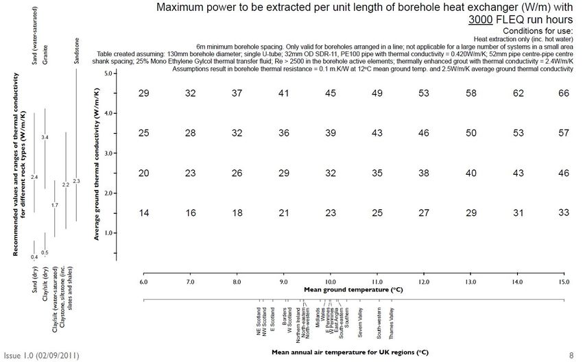
Vapour compression cycle – accounts for >90% of heat pumps
worldwide
According to the First Law: Qc Qe Wc
Practical cycle, for a heat pump: CoP Qc / Wc Qc / (Qc Qe )
CoPRefrigerator Qe / Wc (Qc Wc ) / Wc (Qc / Wc ) 1 CoPHeatPump 1
That is: CoPHeatPump CoPRefrigerator 1
(Figures reproduced courtesy of the US DOE Office of Energy Efficiency and Renewable Energy)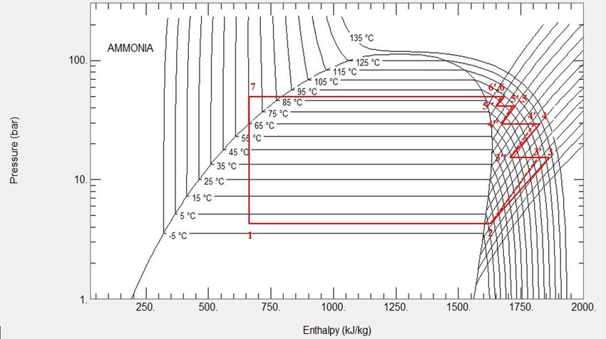
So what? In the UK alone 300,000 domestic gas boilers are replaced every year. At best, each operates at a seasonal mean efficiency of 0.92 (*). Each will discharge 0.184/0.92 = 0.2kg of CO2 to the atmosphere per unit of energy delivered to the connected heating system (**). Today in the UK, a heat pump, operating with a CoP of 3, will discharge 0.352/3 = 0.117kg of CO2 – nearly 42% less than the best gas boiler. In 2015, the same heat pump would have discharged 0.15kg of CO2 – 25% less than the gas boiler The reduction in CO2 emission since 2015 is the result of the electricity grid decarbonising in the meantime * Recent surveys suggest that as many as 90% of UK domestic gas boilers rarely condense which means that their seasonal efficiencies are more likely to be around 0.85. ** https://www.gov.uk/government/publications/greenhouse-gas-reporting-conversion-factors-2017 (accessed 7th August 2017)
UK domestic space and hot water energy by technology to 2050

                                                                                             (Notwithstanding fracking,
                                                                                             the pressure is on to diversify
                                                                                             away from gas for those
                                                                                             countries without indigenous
                                                                                             reserves)

Source: The future of heating: Meeting the challenge. London: Department of Energy and Climate Change.
[Online] Available at:
https://www.gov.uk/government/uploads/system/uploads/attachment_data/file/190149/16_04-DECC-The_Future_of_Heating_Accessible-10.pdf
(accessed November 2014)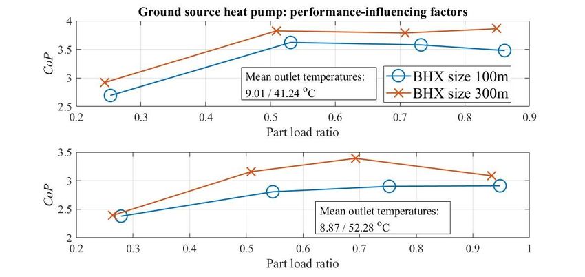
Heat pumps – a review of the technology
Well established 1st and 2nd generation technologies…
            Brazed plate condenser
            (typical ‘pinch’ 2-3K)

                               Working fluids – R134a or
                               zeotropic blends R407C, R410A
Mechanical thermostatic
expansion valve
                                                                           Scroll
                                         OR
                                                                           compressor

                      Water source - brazed        Air source – fin-and-coil
                      plate evaporator             Evaporator (typical ‘pinch’
                      (typical ‘pinch’ 2-3K)       3-5K)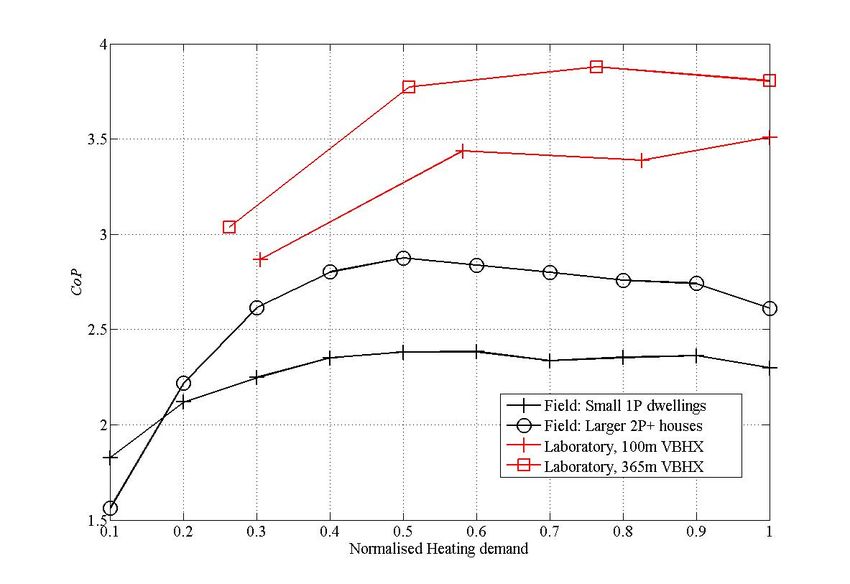
Working fluids – pure fluid R134a
Working fluids – binary near-azeotrope blend R410A
Working fluids – ternary zeotropic blend R407C
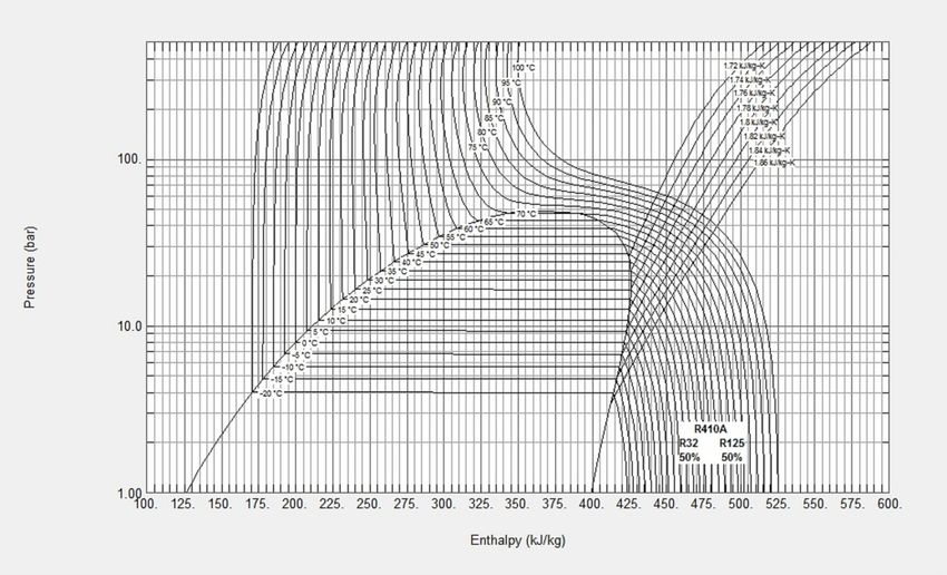
Common working fluids compared

FLUID              TYPE                GWP (*)             COMMENT

R134a              Organic HFC          1430            Mainly commercial

R407C              Organic HFC blend    1774           Domestic/commercial

R410A              Organic HFC blend    2088           Domestic/commercial

R32                Organic HFC           675      Not yet widespread; flammability

R290               Organic HC            3.3        Mainly process; flammability

R717 (ammonia)     Inorganic              ?                   Toxicity

R744 (CO2)         Inorganic              1           Low critical temperature

 *Global warming potential – the global warming effect with reference to CO2
Theoretical performance
275kJkg-1 417, 422kJkg-1, 451kJkg-1, 465kJkg-1
For an overall compressor isentropic efficiency of 0.65...
451 275 465 275
Ground source: CoP 0.65 3.9 Air source: CoP 0.65 =2.6
451 422 465 417
(Typically, the source pump will reduce CoPGS by up to 5% and the source fan CoPAS by up 10%)Typical compressor efficiencies are key
Seasonal performance factor, SPF vs. CoP

       SPFH4
       SPFH3
       SPFH2

                                                      DHW       HEATING
                                                      TANK      BUFFER
                                                                TANK

                          HEAT
                          PUMP

                           SPFH1

e.g. SPFH3 = (Qc + Ecassette) / (WHP + Wsrc pump + Ecassette)
Reverse cycling for air conditioning and defrosting
Condenser These refinements
permit the same plant
to operate as a heat
pump in winter and
HtgR ChwR
an air-conditioner in
HEAT PUMP MODE
Evaporator
summer.
HtgF ChwF
Source
Evaporator
HtgR ChwR
Condenser
REFRIGERATION MODE HtgF ChwF
SinkDefrosting in air-source heat pumps
DEFROST EVENT DYNAMICS - POWER AND HEAT
15 Periodic defrosting is needed in
Power consumed air-source heat pumps. In UK
Heat delivered conditions this will typically
10 arise at external air temperatures
< 7 oC.
5 At these lower external
temperatures, the refrigerant in
kW
the evaporator drops to below
0 0 oC. Thus, water condensing in
the air being cooled across the
evaporator subsequently turns to
-5 ice as it settles on the evaporator
surface. Typically in UK
conditions, defrosting will add a
-10 8-10% ‘overhead’ on annual
0 1 2 3 4 5
power consumption.
Time (minutes)
(Typical domestic heat pump example)Ground sourcing alternative – typical array capacities Source: Microgeneration Certification Scheme – MCS 022 Ground Heat Exchanger Look-up Tables, 2008. Available at: http://www.microgenerationcertification.org/mcs- standards/installer-standards (accessed April 2014)
Performances in practice
Practical performances – air-source
3
2.8
2.6
CoP
2.4
2.2
Defrost excluded
2
Defrost included
1.8
2 4 6 8 10 12 14 16
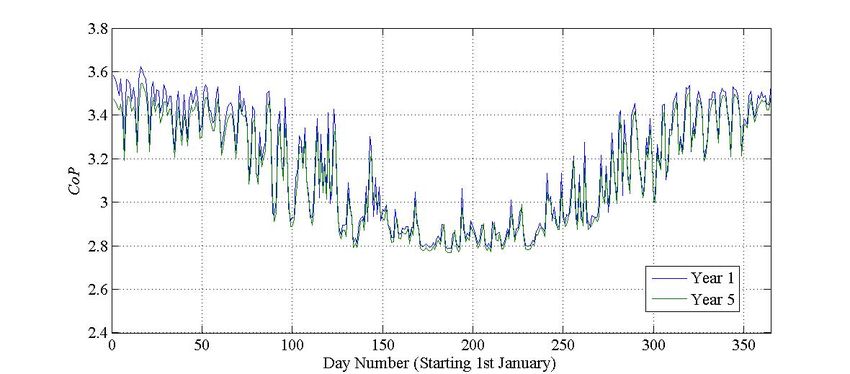
External air temperature (dg C)Practical performances – ground-source
Field-trialled UK performances
First year (2009/10) results of UK field trials conducted at 82 domestic sites of ground- and air-source
heat pumps…

Source: Getting warmer: a field trial of heat pumps. London: The Energy Saving Trust.
[Online] Available at: http://www.heatpumps.org.uk/PdfFiles/TheEnergySavingTrust-GettingWarmerAFieldTrialOfHeatPumps.pdf
(accessed December 2013)
Compared with Germany…

This shows results obtained by the Fraunhofer Inst. from 68 German ground source heat
pumps in new low energy houses, the majority (93%) of which used underfloor heating. The
annual mean SPF is 3.8. For air source heat pumps the annual SPF was 2.9 (new houses) and
2.6 (existing); the main differences being the lower insulation standard and the predominant
use of radiator heating in the existing houses.

Source: Miara, M. (2009). Heat Pumps in Action. RenewableEnergyWorld.com. [Online] Available at:
http://www.renewableenergyworld.com/rea/news/article/2009/10/heat-pumps-in-action
(accessed November 2014)
SPFs compared
     COUNTRY                                       SOURCE                         SITES                            MEAN
     Sweden                                        Ground                            6                               3.26
     Germany - existing                            Ground                           36                               3.30
     Germany - new build                           Ground                           56                               3.88
     UK phase 1 trials                             Ground                           49                               2.31
     UK phase 2 trials                             Ground                           21                               2.82
     BEIS/UCL RHPPP trials                         Ground                           223                              2.75
     Germany - existing                            Air                              34                               2.60
     Germany - new build                           Air                              18                               2.89
     UK phase 1 trials                             Air                              22                               1.83
     UK phase 2 trials                             Air                              15                               2.45
     BEIS/UCL RHPPP trials                         Air                              76                               2.30

Gleeson, C.P., & Lowe, R. (2013) Meta-analysis of European heat pump field trial efficiencies. Energy and Buildings 66, 637-47.

Getting Warmer – a Field Trial of UK Domestic Heat Pumps. Energy Saving Trust, UK. [Online] available at:
http://www.heatpumps.org.uk/PdfFiles/TheEnergySavingTrust-GettingWarmerAFieldTrialOfHeatPumps.pdf

The heat is on: Heat pump field trials phase 2. UK: Energy Saving Trust, UK. [Online] available at:
https://www.gov.uk/government/uploads/system/uploads/attachment_data/file/225825/analysis_data_second_phase_est_heat_pump_field_trials.pdf

DECC, Detailed analysis of data from heat pumps installed via the Renewable Heat Premium Payments Scheme, 2017, [Online] available at:
https://www.gov.uk/government/publications/detailed-analysis-of-data-from-heat-pumps-via-the-renewable-heat-premium-payment-scheme
(Accessed 18 August 2016)
So why do UK systems perform so badly? Sizing of the heat pump itself – risk-averse design the main culprit. Sizing of the array (ground-source). Control factors – defrosting (air-source); inappropriate (or lack of) use of weather-compensating control. Choice of heating – underfloor versus radiators (especially problematical in retrofit applications). Thermostatic controls (especially with inappropriate buffering) Domestic hot water storage temperatures and tank pasteurisation.
Part-load performances
Part load problems also evident during summer months even
               with good heat pump sizing…
Impact of poorly-sized sized array (ground-source)
Social factors* The highest 10% of gas users consume four times as much as the lowest 10% but are unaware of this. About 40% of this variation can be explained by physical factors (property type, age, size, insulation standard). A major part of the remaining 60% is due to social factors – how the occupants behave (comfort temperature choice; time spent at home; use of windows, etc). Even the lowest 10% have the potential to reduce energy use without affecting comfort. * Fell, D. & King, G. (2012). Domestic energy use study: To understand why comparable households use different amounts of energy. London: DECC.
Some challenges for the future
Where now? (Suggestions for further R & D)
The potential for ground source heat pumps to reduce household energy bills and deliver carbon
savings has been shown to be excellent and the market size is substantial.
Existing performances in the field are not good enough – earlier slides have shown that seasonal
CoPs must be at least 3 to be viable.
Between 1995 and 2003, domestic heat pump efficiencies improved by 20% due to continuous
product improvement during those years (Gleeson & Lowe – slide 24).
Though there are numerous reasons for poor performances in the field, the following issues are
repeatedly mentioned…
Heat pump sizing – in particular the avoidance of over-sizing (consider the use of dynamic thermal
modelling to size the heat pump rather than current practice which uses a steady-state energy balance
with ‘worst case’ boundary conditions).
Heat pump technology – a rapid move to 3rd generation technology using variable speed compressor
drives and electronic expansion devices is needed.
Heat pump integration – increased buffering through the use of phase change materials.
System controls – life beyond the thermostat can be found using AI methods the most promising of
which for this type of problem is fuzzy set theory.
Ground array design – simulation tools are maturing and becoming robust and reliable but most have
impracticable computational demands; simplified but reliable design-sizing tools such as ‘g-functions’
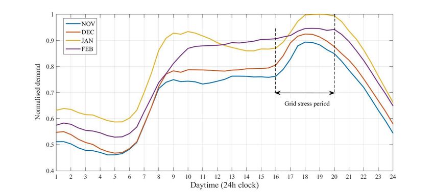
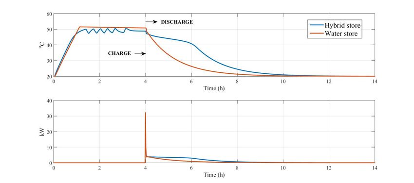
need to become more widely available for practitioners.The challenge of grid stress – grid reinforcement or storage?
Smart thermal storage to alleviate grid stress

Hybridisation of phase change material in a water storage tank
Hybridisation – an interim way forward?

                                 Hot water
Large scale applications – district sourcing by mine dewatering
Other developments

Thoroton and Croft Estate, Blyth

Option 1: DISTRIBUTED SOURCE
(Independent Heating)

                                   Source water
                                   circuit

            Raw mine
            water                                 Typical house
               Pump House                         connections
Heat networks – the Drammen fjernvarme heat pump…
• The Drammen fjernvarme district heating plant in Norway hosts the world’s largest seawater source
heat pump plant
• Total capacity 14MW based on 3 multistage single-screw compressor ammonia heat pumps
generating hot water at 90oC (peak) flow, 60oC return generating 67GWh of heat per year
• Single-screw compressors used with a maximum discharge temperature of 135oC; the cycle for this
high lift application is managed through a series of compression stages each followed by a
desuperheat (and oil cooling) process
• Single screw compressors used because they are expected to enjoy longer bearing life than their
more efficient twin-screw counterparts
• Source: north sea water from the Oslo fjord, drawn 18m below the seawater surface at constant year-
round temperatures of 8-9oC (4oC evaporator outlet temperature)
• Operating pressures 4.4bar (evaporating – superheated to 6oC); 26bar (intermediate) and 50bar
(condensing – sub-cooled to 65oC) – the three heat pumps are connected in series hence these
conditions are nominal
Further reading…
http://www.ammonia21.com/web/assets/link/Hoffman7thApril2011London%20colour.pdf (accessed
November 2015)‘High lift’ heat pump cycle for use with heat networks
And, finally, economics: The UK’s Renewable Heat Incentive – a financial ‘leg
             up’ for heat pumps and other thermal technologies…
 •     Launched in 2011 (non-domestic) and 2014 (domestic)
 •     Tariff support for a range of renewable heat emitter systems to incentivise take-
       up of these new technologies
 •     From 1st July 2017 in the non-domestic RHI, ground- and water-source heat
       pumps receive a tariff payment of 9.09p/kWh (for the first 15% of full load
       equivalent hours ‘FLEH’) and 2.71p/kWh (for the remainder) applicable to the
       renewable (source) heat only and payable for 20 years
 •     The tariff for air-to-water heat pumps is 2.71p/kWh and strictly for heat pumps
       (i.e. reverse cycle heat pumps with summer cooling are ineligible)
 •     The tariff payments in the domestic RHI are 7.63p/kWh (air-source) and
       19.64p/kWh (ground-source) but are payable for just 7 years
 •     To be eligible, the heat pump must have a minimum seasonal performance
       factor (SPF) of 2.5 (the SPF is defined in the same way as the CoP but
       represents a value averaged over the entire heating season)
 •     Note that the above is subject to change

     Further details:
     http://www.ofgem.gov.uk/environmental-programmes
You can also read