CLASSIC HANDLE - Dino Paoli
←
→
Page content transcription
If your browser does not render page correctly, please read the page content below
MANUALE D’USO E MANUTENZIONE
OPERATING AND MAINTENANCE MANUAL
MANUEL D’UTILISATION ET D’ENTRETIEN
HANDBUCH FUR GEBRAUCH UND WARTUNG
MANUAL DE INSTRUCCIONES

    CLASSIC HANDLE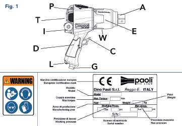
Thanks for choosing a PAOLI product.

           Behind your impact wrench you have
     the capacity and the diligence of a company team
    which is working all the days to be able to offer you
    always powerful, reliable and long lasting products.

            From the Pit Lanes to any businesses,
                  your success is our goal!

         Grazie per aver scelto un prodotto PAOLI.

              Dietro il vostro avvitatore ci sono
       la capacità e l’impegno di un team aziendale
che lavora tutti i giorni per essere in grado di offrirvi sempre
    dei prodotti potenti, affidabili e durevoli nel tempo.

            Dalle Pit Lanes a ogni tipo di attività,
           il vostro successo è il nostro obiettivo!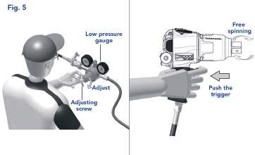
DINO PAOLI s.r.l.
Via G. Dorso, 5 - 42124 Reggio nell’Emilia (RE) - Italy
Phone +39 0522 364 511 - Fax +39 0522 304 864
info@paoli.net - www.paoli.net
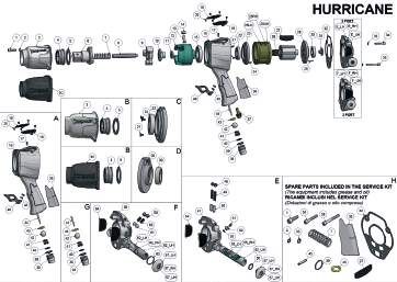
HURRICANE
4
OPERATING AND MAINTENANCE MANUAL
Safe operation of this tool is possible only when the operating instructions
are read completely and the instructions contained therein are strictly
observed.
The addresses of these instructions are professionals trained.
THESE INSTRUCTIONS MUST ALWAYS BE WITH THE IMPACT WRENCH.
KEEP THEM IN A SAFE PLACE.
14
MANUALE D’USO E MANUTENZIONE
Per poter lavorare con l’avvitatore senza esporsi a situazioni di pericolo
è necessario leggere completamente le presenti istruzioni per l’uso
e rispettare rigorosamente le indicazioni ivi contenute. I destinatari di
queste istruzioni sono operatori professionali adeguatamente formati.
QUESTE ISTRUZIONI DEVONO SEMPRE ACCOMPAGNARE L’AVVITATORE.
CONSERVARE CON CURA.
24
MANUEL D’UTILISATION ET D’ENTRETIEN
Travailler sans danger avec cet appareil n’est possible qu’à condition
de lire intégralement la notice d’instructions et de suivre le instructions
qui figurent dedans. Les destinataires de ces instructions sont des
professionnels formés.
CES INSTRUCTIONS DOIVENT TOUJOURS ACCOMPAGNER LA CLÉ À
CHOC. GARDER AVEC SOIN CE MODE D’EMPLOI.
34
HANDBUCH FUR GEBRAUCH UND WARTUNG
Gefahrloses Arbeiten mit dem Gerät ist nur möglich, wenn Sie die
Bedienungsanleitung vollständig lesen und die darin enthaltenen
Anweisungen strikt befolgen. Die Empfänger dieser Anleitungen sind
entsprechend geschulte Fachkräfte.
DIESE ANWEISUNGEN MÜSSEN IMMER MIT DEM SCHRAUBENDREHER
SEIN. BITTE SORGFÄLTIG AUFBEWAHREN.
44
MANUAL DE INSTRUCCIONES
Para poder trabajar sin peligro con el aparato, debe Ud. leer
completamente las instrucciones de manejo y seguir estrictamente las
indicaciones allí descritas. Los destinatarios de estas instrucciones son
operadores profesionales correctamente capacitados.
ESTAS INSTRUCCIONES TIENES QUE ACOMPAÑAR SIEMPRE LA LLAVE
54
DE IMPACTO. CONSERVAR CON CUIDADO.
ALLEGATI • ATTACHMENTS
Schede Tecniche • Technical Charts
Elenco Ricambi • Spare Parts
Dati Tecnici • Technical Data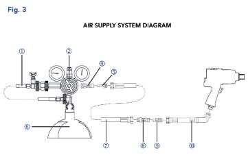
OPERATING AND MAINTENANCE MANUAL

TECHNICAL DATA
DESCRIPTION                                               INTENDED USE
Portable air impact wrench designed for                   Assembly air tool for threaded fasteners in the
motorsport application (Best Practice: F1,                pit stop service.
Indycar, Formula 2, DTM, Endurance).
                                                                       Weight (kg)                  3,70***
LUBRICANT
                                                                      Length (mm)                     200
Hammer mechanism lubrication: Special
grease for Paoli air impact wrench hammer                             Square drive                    1”
mechanism.                                                              Air inlet                  3/8” BSP
Air motor lubrication: Very fluid oil for air tools            Supply hose inside diameter       1/2” (13 mm)
or Special oil for Paoli air impact wrench motors.
                                                               Maximum free speed (RPM)       15.000** (at 25 bar)
ENVIRONMENTAL CONDITIONS                                        Max weight recommended
                                                                                                     0,70
Temperature: -5 ° C ÷ + 45 ° C                                     power socket (kg)
Storage temperature: 0 ° C ÷ + 40 ° C                          Operating air pressure (bar)      25 (maximum)
Air humidity:
OPERATING AND MAINTENANCE MANUAL
GENERAL INSTRUCTIONS
LL Wheel gun intended to be used for LL Do not use the wheel gun with the screws of
professional use by trained personnel and the clutch cover (view figure Fig.1-E) or the
equipped with appropriate technical skills. motor cover (view figure Fig.1-P) loose or not
LL Do not operate the wheel gun without the tight enough (see table Tab. A “Tightening
prescribed safety devices. Torques”). If not tighten them with a torque
LL The drive shaft of the wheel gun and the wrench following the tightening sequence
socket fixed to it may continue to rotate for shown (view figures Fig.2-F and Fig.2-G).
a short time after the release of the trigger. LL Pay attention to the exhaust coming out
LL Verify that the WARNING label (view figure by the wheel gun during operation (view
Fig.1-W) is present and legible, otherwise figure Fig.2-B). To avoid compromise the
replace it by applying new one in the original performance of the wheel gun, not obstructed
position. in any case these holes of exhaust.
OPERATING INSTRUCTIONS
LL At the first use it is necessary to adjust the LL The standard adjustment of the force
oiler (view Maintenance chapter). necessary for the translation of the rotation
LL Always use a wheel gun with the tightening reverse shaft, and thus the reverse is
torque corresponding to the one required already performed by Dino Paoli s.r.l.. A
by the application. personalized set of this force is possible,
however, for specific needs of the operator,
LL Please pay attention to your wheel gun version: acting uniformly on the nr.2 (two) rotation
⚪⚪ the Fast Left Hand (LH) version loosens reverser grub screws (view figure Fig.2-C).
nuts tightened clockwise faster; Tightening the grub screws you will have
⚪⚪ the Fast Right Hand (RH) version loosens an increase in the force required, loosening
nuts tightened anticlockwise faster; them you will have its decrease. Ensure
⚪⚪ the Unhanded (UH) version loosens at that the individual regulation does not
same speed both the nuts tightened create problems of accidental reversal
clockwise and anticlockwise. of the direction of rotation. Perform this
adjustment always disconnected the wheel
LL In order not to compromise the functionality gun from the air supply.
of the wheel gun, do not unscrew or loosen
never the grub screw of the gun body (view LL The modes for the correct grip intended
figure Fig.2-H). for use of the wheel gun is as follows (view
figure Fig.2-E):
LL In order not to compromise the functionality
of the rotation reverse shaft, do not unscrew ⚪⚪ right hand grip on the gun body;
or loosen never the grub screw of the motor ⚪⚪ left hand grip on the surface of the hammer
cover (view figure Fig.2-D). case.
Original operating instructions - The original language of these instructions is English.
TAB. A TIGHTENING TORQUES
Clutch Cover M6 Screw 16 Nm
Motor Cover M5 Screw 10 Nm
ENGLISH 5OPERATING AND MAINTENANCE MANUAL
REGULATION OF HANDLING
THE AIR PRESSURE
LLPlease pay attention to your wheel gun
LLBefore the use, always perform a selector plate type (3 port or 2 port
dynamic adjustment of the supply air version).
pressure (view figure Fig.5). Adjust the
supply air pressure on the low pressure LL Slide the rotation reverse shaft (see figure
gauge turning the adjusting screw of the Fig.1-I) and push the trigger (view figure
air pressure regulator while keeping the Fig.1-C). See the figure Fig.4 to identify
trigger pressed. the rotation direction of the square drive.
LLDo not exceed the maximum supply LL Avoid accidental starting, being careful not
air pressure of 25 bar (with wheel gun to unwittingly act on the trigger (view figure
running). Fig1-C).
INSTALLATION OF ACCESSORIES
Before changing an accessory, always make LL Using an appropriately sized aluminum
sure that the air supply line is depressurized (no block, support the 1” square drive from
air pressure), and only after disconnecting the the bottom. This will provide the base for
wheel gun and replace it. Use only accessories pressing the socket onto the square drive.
suitable for the job (view our catalogue for Make sure the block is tall enough to allow
accessories). Use only impact sockets with a clearance for the clutch cover.
hole for the locking pin.
Do not use chrome sockets or for manual use. LL In ideal situations, an aluminum block
Do not use square drive adapters (reductions should be machined to fit either the I.D.
or multiplies). or the surface of the socket. This will be
Always check that the locking pin of the socket used for pressing the socket onto the
is present and secured firmly. To install the square drive. Special attention must be
wheel nut socket, proceed as follows: taken to assure the inner O-ring groove
LL Mark each clutch cover with the wheel gun’s (retention ring) is not damaged by a tool
serial number. used on the socket I.D.. A tool used on the
magnet surface (i.e. for wheel nut sockets
LL Remove the four clutch cover (hammer with magnets) should also fit properly to
case) screws, discard lock washers. prevent damage to the magnets. In certain
LL Holding the 1” square drive, remove the situations a thick block of aluminum can
anvil shank, clutch cover bearing and clutch be used to press directly on the teeth
cover from gun. Clutch spring should of the socket (i.e. for wheel nut sockets
remain with clutch shaft, clutch plate and with fingers) for installation. This is not a
clutch housing. Retain the anvil shank, recommended practice and should only
clutch cover bearing and clutch cover as an be used when a proper press tool cannot
assembled unit. readily be made.
6 ENGLISHOPERATING AND MAINTENANCE MANUAL
LLThe sockets are designed to have a LLSocket pins can be staked in one of two
press fit on the 1” square drive. Sockets ways.
and 1” square drives should never be
⚪⚪One is to use two 45 deg. center
modified to allow a hand press fit or a
punches. Place one punch point up in
slip on installation. Older sockets that
slide freely on square drives should be vice jaws and clamp down. With the
replaced. help of an assistant, position the socket
pin in the center of the socket, place
LLIMPORTANT: If there are magnetic socket and pin on punch point in vice.
parts and rubber in the socket under Using a second punch and hammer
no circumstances should it be heated strike the top of the socket pin. This
to assist the installation onto the square action should be enough to stake both
drive. Heating the socket will compromise the top and the bottom of the pin,
the magnet’s holding power and destroys repeat operation if necessary.
the epoxy bold that holds the magnets in
the socket. ⚪⚪The second method of staking socket
pins is the use of a staking tool. A
LLPlace anvil shank, clutch cover bearing
staking tool can easily be produced
and clutch cover on lower aluminum
by incorporating a fixed bottom stake
support block. Lubricate the square
point, a square or “U” shaped yoke
drive and internal square on socket with
and a sliding top stake point or punch.
appropriate press fit lubricant. Most anti-
This tool can be used with either a
seize, anti-galling compounds will work.
hammer or a press.
LLPlace the anvil shank along with the
LLAfter the socket pin has been staked,
clutch cover assembly and support block
any part of the pin protruding out of the
in a press, adjust height accordingly.
socket will need to be ground flush. This
LLAlign the cross holes for the socket pin on can be done with a right angle die grinder
both the socket and square drive. Insert and a medium Scotch-Brite wheel. Avoid
top press block in or on socket. Making grinding any titanium surfaces of the
sure the stacked assembly is square; socket. Pay close attention not to leave
begin pressing the assembly together any rough or high points that may cause
using low pressure. As the socket is being hand injury during use.
installed it may be necessary to go to the
high pressure setting on your hydraulic LLApply some of the metal strip on the
press. outside diameter of the socket to
coincide with the locking pin to prevent
LLWhen the cross holes on the socket any unexpected slippage of the pin.
and square drive near alignment, install
socket pin in socket. While applying side LLMatch coordinating clutch cover
pressure to the pin continue to press assemblies and guns. Re-install the
the socket onto the square drive. When socket and clutch cover assembly on
the holes are aligned the pin will slide wheel gun using the four screws and new
through easily. lock washers.
ENGLISH 7OPERATING AND MAINTENANCE MANUAL
MAINTENANCE INSTRUCTIONS
Before any maintenance, always make LLIndicate the parts most subject to wear,
sure that the air supply of the wheel gun to be dismantled and checked at regular
is depressurized (no air pressure), and intervals, as well as a list of malfunctions,
only after unplugging the wheel gun and if any, and the corrective action.
performing maintenance.
LLUse only genuine spare parts and
LLUse only recommended lubricants. authorized service organizations.
LL Every 20-30 cycles it is recommended to fill LLBefore every race it is strongly
(special oil for Paoli air impact wrench motors recommended to run the wheel gun
or very fluid oil for air tools) the oil tank, by clockwise and anticlockwise (please pay
loosening (use a 14 mm hexagonal key) the
attention to the exhaust coming out
oiler block in the bottom side of the wheel
from the top of the wheel gun during
gun; then tighten again the oiler block (view
this operation - view figure Fig.2-B)
figure Fig.2-A). The oil tank capacity is ~ 8 cc.
putting special oil for Paoli air impact
These operations alow to keep the appliance
wrench motors (~5cc) or very fluid oil
efficient and to extend its service life.
for air tools into the air inlet. These
LL Setting the oiler: to change the setting, operations must be performed in a
unscrew the locknut 1 with a 10 mm hexagon suitably equipped working environment,
English key (view figure Fig.2-A) and then complete with extraction equipment
screw or unscrew the shutter 2 with a cutting for nebulised particles. Use personal
screwdriver (view figure Fig.2-A) to obtain protective equipment.
a smaller or greater flow. After adjustment,
tighten locknut 1 to lock the setting. LLIf the wheel gun is left unused for
long periods we recommend putting
LLShip the wheel gun back to the PAOLI some oil (special oil for Paoli air impact
facilities at least once per year for the
wrench motors) into the air inlet (view
complete overhauling.
figure Fig.2-I) and letting it run for a few
LL Do not carry out maintenance with improper seconds before putting it away. In this
tools, make use of the attached exploded way the internal components will remain
drawing with the list of spare parts. lubricated.
SCRAPPING
Separate the components on the basis of the nature of the materials of which they are made. The
components must be disposed of according to the laws in force.
8 ENGLISHSAFETY INSTRUCTIONS
CAUTION Wear suitable clothing. Do not wear clothing or
jewellery which could get caught in moving parts.
When you use compressed air tools, always check Protective gloves and non-slip safety shoes should
that the safety regulations which apply in your be worn when working outside. Long hair should
workplace are respected, as well as those in the be kept in a hairnet.
following instructions, in order to reduce the risk
Use personal protection. Your should always wear
of environmental and personal damage. noise-proof ear protection, safety goggles with
ww Wear safety glasses and hearing protection. de-mist screen, work gloves, filtered mouth mask
and anything else necessary to prevent contact
ww If necessary, wear dust mask and gloves. with harmful substances and sub-products of the
ww Wear suitable working clothes and safety shoes. working process.
ww Do not use the tool continuously, do a break Connection the power supply. This should always
periodically be done in respect of local safety regulations. In
the case of compressed air, care should be taken
For operator safety: to avoid whiplash (in case of tube breakage), or
accidental unplugging, and the danger of short
Keep the work area clean. An untidy workplace or circuiting for electrical connections.
bench may cause personal damage.
Risks of discharged air containing lubricator or
Check the conditions of workplace. Check that residues. Avoid excessive lubrication and inhaling
the lighting is adequate. If the materials being the discharged air; the work place should be
worked produce sparks, do not use the tools equipped with conveyor ducts for the discharged
in the presence of inflammable liquids, gases air where necessary.
or material. Do not use the tool in potentially Check that the mains electricity supply complies
explosive atmospheres (ATEX). with safety regulations and the requirements
stated in the instructions manual before
Keep unauthorised persons at a safe distance.
connecting up.
Do not let them touch the tools. Visitors should be
kept away from the workplace. Connect the equipment for dust extraction. If the
equipment for dust collection is included, check
Do not overload the tools. They will work better that these are connected to the tools and used
and in safe conditions if they are fitted with suitable correctly.
tubing and are used at the pressure indicated in
this manual. Check that the infeed tube is used correctly. Do
not drag the tool connected to the power supply
Use the right tool. Check the conditions of the by pulling the tube. Keep the tube away from
working tools (impact sockets, etc.) before each sources of heat and sharp objects.
start-up and replace if damaged or worn.
Fasten the part to be worked. Use fastening
Improper uses and absolutely forbidden: devices to keep the part still. This is safer than
using your hands and in this way they will both
ww Use the tool for any purpose and uses different
be free for working with the tool. Check that a
from that required in this manual firm resting point is always available and that the
ww Direct the tool or accessories against people position is well-balanced.
or animals
Always keep a good grip on the handle of
ww Use the tool or accessories like hammer, lever the tool, using special auxiliary devices where
or blunt object necessary. This will serve to reduce body vibration.
ENGLISH 9Accessories being operated. Do not touch parts using the tool, carefully check that the safety
and/or accessories of the tool which are moving device and other parts are in perfect working
or working. conditions. Check that the moving parts are not
damaged, that they are free to move, and check
Pay attention. Always pay attention to what are
any other conditions that could limit the operation
you doing. Proceed with care. Do not work when
of the tool. A damaged protective device or
you are tired.
other component must be replaced or repaired
Look after the tools. Keep them clean and in good by an authorised Servile Centre unless otherwise
condition so that better results may be obtained indicated in this manual.
safely. Never remove protection or silencers from
the tool. Follow instructions for maintenance and The tool does not emit non-ionizing radiation.
for replacing the accessories. IMPORTANT. The use of accessories and spare
Use and assembly of the accessories. This should parts other than those recommended in this
be done according to the machine instructions manual may cause personal harm.
manual. The use of accessories or assembly other Do not alter any element of the machine or
than those recommended may cause personal harm. remove protective or safety devices, or elements for
Switch off the power supply. After each work session checking the outgoing air flow (filters, deflectors,
and before performing calibration, maintenance or etc.) without explicit authorisation from PAOLI.
replacement operations on the accessories such Stop work immediately should vibrations or
as impact sockets, etc., you are recommended to strange noises occur, or if the tool starts operating
switch of the power supply to the tool.
differently.
Remove the service keys. Before using the tools,
The tool should be repaired by a qualified
always check that the service or adjusting key has
personnel. This compressed air tool complies
been removed.
with current safety regulations. Repairs must be
Check damaged parts. When the goods are done by qualified personnel, using original spare
received, check that the packaging is intact and parts, otherwise serious harm may be caused to
there are no signs of knocks or tampering. Before the operator.
LIST OF RESIDUAL RISKS
⚪⚪ Moving parts ⚪⚪ Vibrations transmitted to the hand-arm
⚪⚪ Rotating elements ⚪⚪ Materials or substances
⚪⚪ Parts with edge ⚪⚪ Low visibility
⚪⚪ Low-light
⚪⚪ High pressure
⚪⚪ Ambient temperature
⚪⚪ High temperature parts ⚪⚪ Repetitive action + noise + environmental
⚪⚪ Noise during the use high-temperature
PACKAGE
The tool is delivered inside a carton box, maintenance, the declaration of conformity,
protected with anti-vibration material. other accessories and lubricants indicated in
Together with the impact wrench inside the this manual of use and maintenance.
box, you will find the manual of use and
10 ITALIANO
ENGLISHOPERATING AND MAINTENANCE MANUAL
PROBLEM SOLVING
PROBLEM CAUSE REMEDY
Start lever tool not fully
Press the start lever
pressed
The pressure or the capacity
Check the line of air
of the line air alimentation is
alimentation
inadequate or nil
The shaft does not rotate Operate in an environment
Temperature too low
with higher temperature
Contact an authorized service
Tool failure
center
Position of the inverter Replace the inverter of
incorrect rotation
Start lever tool not fully
Press the start lever
pressed
The pressure or the capacity
Check the line of air
of the line air alimentation is
alimentation
inadequate or nil
Read the instructions and
Performance Drop Absence of lubrication
lubricated the tool
Dirty filter Clean the filter
Position of the inverter Replace the inverter of
incorrect rotation
Contact an authorized service
Tool failure
center
The tool is not well supported Rest well the socket on the
to the nut nut
The accessories are not
The tool vibrates Connect correctly accessories
connected properly
abnormally
The accessories are worn Replace the accessories
Contact an authorized service
Tool failure
center
The shaft does not stop
despite the start lever is Start lever jammed Disconnect the power supply
not pressed
ENGLISH
ITALIANO 11EC DECLARATION OF CONFORMITY
Individual machine
We
DINO PAOLI S.R.L. - Via G. Dorso, 5 - 42124 Reggio Nell’Emilia (Re) - Italy
declare under our sole responsibility that the product:
Machine Type
HURRICANE
Air impact wrench
TECHNICAL DATA
View Attachments Section
SERIAL NO.
View back cover
to which this declaration relates, is in conformity with the requirements
of the Machinery Directive 2006/42/EC
Name and address of the person authorized to draw up the technical file
Nome: Dr. Federico Galloni
Address: DINO PAOLI S.R.L. - Via G. Dorso, 5 - 42124 Reggio Nell’Emilia (Re) - Italy
Name and position of issuer:
Il Direttore / Managing Director Dr. Federico Galloni
Reggio nell’Emilia (RE) - Italy - November 6, 2017
12 ITALIANO
ENGLISHDINO PAOLI s.r.l.
Via G. Dorso, 5 - 42124 Reggio nell’Emilia (RE) - Italy
Phone +39 0522 364 511 - Fax +39 0522 304 864
sales@paoli.net - www.paoli.net
TERMS AND CONDITIONS OF THE MANUFACTURER’S
LIMITED WARRANTY
The terms and conditions of the warranty provided by DINO PAOLI S.r.l. are:
⚪⚪ A warranty period of twelve months from the ⚪⚪ Complete replacement of the product is
date of purchase, limited to demonstrable not envisaged, except for a clear defect
defects in materials or manufacture. The
that has been reported within eight days of
receipt must be provided as proof of the
date of purchase. In the case of an impact receiving the product. In contrast, we will
wrench, the registration number of the replace under warranty the components
impact wrench must also be provided.
necessary to restore its correct functioning,
⚪⚪ DINO PAOLI s.r.l. may not be held liable, including labour.
and will not accept any claims, for damages
caused by improper use that does not ⚪⚪ Any replacement of components under
comply with the manufacturer’s instructions. warranty is at the sole discretion of DINO
PAOLI s.r.l., after it has received them.
⚪⚪ The warranty is not valid if the product
The replaced components will remain the
has been used in a manner that does not
comply with the manufacturer’s instructions. property of DINO PAOLI s.r.l.
The warranty is not valid if the product
has been repaired by personnel who have ⚪⚪ The product may be delivered to a centre
not been specifically authorised by DINO authorised by DINO PAOLI s.r.l., which will
PAOLI s.r.l. deal with the product. A list of authorised
centres is available at the e-mail address
⚪⚪ Technical interventions during the warranty
sales@paoli.net. Alternatively, the product
period do not extend or renew said warranty
period; said repairs or replacements are may be sent to DINO PAOLI s.r.l., but the
guaranteed for the remaining period of the shipping costs will not be paid by DINO
original warranty. PAOLI s.r.l.
ENGLISH
ITALIANO 13MANUALE D’USO E MANUTENZIONE
DATI TECNICI
DESCRIZIONE USO PREVISTO
Avvitatore portatile pneumatico ad impulsi Utensile per l’assemblaggio di elementi di
progettato per applicazione motorsport (Indicato collegamento filettati nei servizi di pit-stop.
per: F1, Indycar, Formula 2, DTM, Endurance).
Peso (kg) 3,70***
LUBRIFICAZIONE
Lunghezza (mm) 200
Lubrificazione masse battenti: Grasso speciale
per le masse battenti degli avvitatori Paoli. Attacco quadro 1”
Lubrificazione motore pneumatico: Olio molto Entrata aria 3/8” BSP
fluido per utensili pneumatici od Olio speciale Diametro interno tubo alimentazione 1/2” (13 mm)
per il motore degli avvitatori Paoli.
Massima velocità a vuoto (RPM) 15.000** (a 25 bar)
CONDIZIONI AMBIENTALI Massimo peso raccomandato per la
0,70
Temperatura di utilizzo: -5°C ÷ +45°C chiave a bussola (kg)
Temperatura di stoccaggio: 0°C ÷ +40°C Pressione pneumatica di utilizzo (bar) 25 (massima)
Umidità dell’aria:MANUALE D’USO E MANUTENZIONE
AVVERTENZE GENERALI
LL Avvitatore destinato ad essere utilizzato per LL Non utilizzare l’avvitatore con le viti di
uso professionale da personale specializzato serraggio del coperchio masse battenti
addestrato e dotato di appropriate (vedi figura Fig.1-E) o del coperchio
competenze tecniche. motore (vedi figura Fig.1-P) allentate o non
LL Non utilizzare l’avvitatore senza i prescritti sufficientemente serrate (vedi tabella Tab.
dispositivi di sicurezza. A “Coppie di Serraggio”). In caso contrario
LL L’albero porta-bussola dell’avvitatore e la serrarle adeguatamente con una chiave
chiave a bussola ad esso fissato potrebbero dinamometrica seguendo l’ordine di serraggio
continuare a ruotare per breve tempo dopo indicato (vedi figure Fig.2-F e Fig.2-G).
il rilascio della leva di avviamento. LL Prestare attenzione all’aria di scarico
LL Verificare che l’adesivo di WARNING (vedi che fuoriesce dall’avvitatore durante il
figura Fig.1-W) sia presente e leggibile, in funzionamento (vedi figura Fig.2-B). Per non
caso contrario sostituirlo applicandone uno compromettere le prestazioni dell’avvitatore
nuovo nella posizione originale. non ostruire in nessun caso tali fori di scarico.
GUIDA ALL’USO
LL Al primo utilizzo è necessario procedere LL La regolazione standard della forza necessaria
alla regolazione dell’oliatore (vedi Capitolo per la traslazione dell’invertitore, e dunque
Manutenzione). per l’inversione di marcia risulta già eseguita
LL Usare sempre un avvitatore con la coppia di da Dino Paoli s.r.l.. Una taratura personalizzata
serraggio corrispondente a quella richiesta di tale forza è però possibile, per
dall’applicazione. specifiche esigenze dell’operatore, agendo
uniformemente sui n°2 (due) grani di fermo
LL Prestare attenzione alla versione del tuo invertitore (vedi figura Fig.2-C). Avvitando i
avvitatore: grani si avrà un aumento della forza necessaria,
⚪⚪ la versione Veloce Sinistro (LH) svita più svitandoli si avrà una sua diminuzione.
velocemente i dadi avvitati in senso orario;
Prestare attenzione che la regolazione
⚪⚪ la versione Veloce Destro (RH) svita più personalizzata non crei problemi di inversione
velocemente i dadi avvitati in senso antiorario; accidentale del senso di marcia. Eseguire tale
⚪⚪ la versione Non Differenziata (UH) svita regolazione sempre con avvitatore scollegato
alla stessa velocità sia i dadi avvitati in dall’alimentazione pneumatica.
senso orario che antiorario.
LL La modalità di presa corretta prevista per
LL Per non compromettere la funzionalità l’utilizzo dell’avvitatore è la seguente (vedi
dell’avvitatore, non svitare od allentare mai il figura Fig.2-E):
grano dell’impugnatura (vedi figura Fig.2-H). ⚪⚪ mano destra in presa sull’impugnatura
LL Per non compromettere la funzionalità principale;
dell’invertitore, non svitare od allentare mai il ⚪⚪ mano sinistra in presa di appoggio sul
grano del coperchio motore (vedi figura Fig.2-D). coperchio masse battenti.
Traduzione dalle istruzioni originali - La lingua ufficiale di queste istruzioni è l’inglese.
TABELLA A COPPIE DI SERRAGGIO
Coperchio masse battenti Vite M6 16 Nm
Coperchio motore Vite M5 10 Nm
ITALIANO 15MANUALE D’USO E MANUTENZIONE
REGOLAZIONE DELLA GESTIONE DEI
PRESSIONE D’ARIA COMANDI
LL Prima dell’uso, eseguire sempre una LL Prestare attenzione alla tipologia di
regolazione in dinamico della pressione invertitore montata sull’avvitatore (versione
di alimentazione (vedi figura Fig.5). 3-port o 2-port).
Regolare la pressione dell’aria di
alimentazione, indicata sul manometro LL Traslare l’invertitore (vedi figura Fig.1-I) e
di bassa pressione, ruotando la vite di premere la leva di avviamento (vedi figura
regolazione del riduttore di pressione, Fig.1-C). Vedere la figura Fig.4 per identificare
mantenendo premuta la leva di avviamento. il verso di rotazione dell’albero porta-bussola.
LL Non superare il limite massimo di 25 bar LL Evitare gli avvii accidentali, prestando
di pressione dell’aria di alimentazione (con attenzione a non agire involontariamente
avvitatore in funzione). sulla leva di avviamento (vedi figura Fig.1-C).
MONTAGGIO DEGLI ACCESSORI
Prima di cambiare un accessorio, accertarsi LL L’utilizzo di un blocco di alluminio, di
sempre che la linea di alimentazione pneumatica dimensioni adeguate, sosterrà l’attacco
dell’avvitatore sia depressurizzata (assenza di quadro dal basso. Ciò fornirà la base
pressione pneumatica), e solo dopo scollegare per la pressatura della chiave a bussola
l’avvitatore e procedere alla sostituzione. Utilizzare sull’attacco quadro. Assicurarsi che il blocco
solo accessori adatti per il lavoro da svolgere sia abbastanza alto per lasciare spazio
(consultare il nostro catalogo accessori). Utilizzare sufficiente per il coperchio masse battenti.
esclusivamente chiavi a bussola ad impulso con
foro per la spina di ritegno. Non utilizzare bussole LL In situazioni ideali, un blocco di alluminio deve
cromate o per uso manuale. Non utilizzare adattatori essere lavorato per adattarsi sia al diametro
di quadro (riduzioni o moltipliche). Controllare interno sia alla superficie della bussola.
sempre che la spina di ritegno della chiave a bussola Questo sarà usato per premere la bussola
sia presente e fissata stabilmente. Per installare una sull’attacco quadro. Particolare attenzione
chiave a bussola, procedere come segue: deve essere posta per assicurare che l’anello
LL Contrassegnare ogni coperchio masse battenti OR interno (anello di ritegno) non si danneggi
con il numero di matricola dell’avvitatore. con l’utensile usato sul diametro interno della
bussola. L’utensile usato sulla superficie dei
LL Rimuovere le quattro viti del coperchio magneti (es. per chiavi a bussola con magneti)
masse battenti, e scartare le rondelle. deve anche adattarsi correttamente per
LL Afferrandolo per l’attacco quadro, rimuovere evitare di danneggiare i magneti. In alcune
l’albero porta-bussola, il cuscinetto del situazioni uno spesso blocco di alluminio può
coperchio masse battenti e il coperchio masse essere usato per l’installazione, per premere
battenti dell’avvitatore. La molla disinnesto direttamente sui denti della bussola (es. per
deve rimanere con l’albero scanalato, chiavi a bussola con dentelli). Questa non è
l’innesto ed il volano. Conservare l’albero una procedura raccomandabile e dovrebbe
porta-bussola, il cuscinetto del coperchio essere adottata solamente quando uno
masse battenti ed il coperchio masse battenti strumento adatto a premere non possa essere
come gruppo montato. prontamente realizzato.
16 ITALIANOMANUALE D’USO E MANUTENZIONE
LL Le chiavi a bussola sono progettate per LL Le spine di ritegno delle bussole possono
avere un inserimento a pressione nell’attacco essere inserite in uno dei due modi.
quadro. Le chiavi a bussola e gli attacchi
⚪⚪ Il primo è quello di utilizzare due punzoni
quadri non dovrebbero mai essere modificati
con estremità a punta di 45°. Posizionare
per permettere un inserimento a mano o
il primo punzone con la punta rivolta
un’istallazione libera. Le vecchie chiavi a
verso l’alto nelle ganasce di una morsa
bussola che scorrono liberamente sul quadro
dovrebbero essere sostituite. e dare un giro di vite. Con l’aiuto di un
assistente, posizionare la spina nel foro
LL IMPORTANTE: Se nella chiave a bussola ci della bussola, disporre la bussola e la
sono parti magnetiche e di gomma, in nessun spina sulla punta del primo punzone fisso
caso deve essere riscaldata per favorire il suo nella morsa. Usando il secondo punzone
inserimento sull’attacco quadro. Riscaldando ed un martello colpire la parte superiore
la bussola si comprometterà la capacità della spina della bussola. Questa azione
di tenuta del magnete e si distruggerà dovrebbe essere sufficiente sia per la
l’epossidico che trattiene i magneti nella parte superiore che inferiore della spina,
bussola. ripetere l’operazione se necessario.
LL Posizionare l’albero porta-bussola, il ⚪⚪ Il secondo metodo di inserimento delle
cuscinetto del coperchio masse battenti e spine delle bussole è tramite l’uso di
il coperchio masse battenti su un blocco un utensile speciale. Tale utensile di
sottile di supporto in alluminio. Lubrificare inserimento può essere facilmente
l’attacco quadro e il quadro interno realizzato usando un blocchetto inferiore
della chiave a bussola con un adeguato fisso con punta, una staffa quadra o “ad
lubrificante per il montaggio a pressa. Sono U” e un blocchetto superiore scorrevole
adatti la maggior parte dei composti anti- con punta o punzone. Questo utensile può
grippanti e antiusura. essere usato sia con un martello che con
LL Posizionare l’albero porta-bussola assieme una pressa.
al coperchio masse battenti completo ed al LL Dopo che la spina di ritegno della bussola
blocco di supporto in una pressa, regolando è stata inserita, dovrà essere eliminata ogni
l’altezza di conseguenza. sua parte sporgente dalla bussola. Per far
ciò usare una smerigliatrice angolare con
LL Allineare i fori trasversali per la spina di
disco abrasivo medio. Evitare di rettificare
ritegno della bussola e dell’attacco quadro.
le superfici in titanio della bussola. Prestare
Posizionare la chiave a bussola sopra il blocco
attenzione a non lasciare zone grezze o
da pressare. Assicurarsi che il gruppo impilato
spigoli che possano causare ferite alle mani
sia allineato; iniziare pressando il gruppo
durante l’uso.
insieme con una pressione ridotta. In fase di
installazione può essere necessario regolare la LL Applicare un giro di nastro metallico sul
pressa idraulica con una pressione superiore. diametro esterno della bussola in coincidenza
della spina di ritegno per prevenire ogni
LL Quando i fori trasversali della chiave a
imprevisto sfilamento della spina.
bussola e dell’attacco quadro sono prossimi
all’allineamento, inserire la spina nella bussola. LL Abbinare ogni gruppo coperchio masse
Mentre si applica una pressione laterale battenti ai rispettivi avvitatori. Rimontare il
sulla spina, continuare a premere la bussola gruppo bussola con coperchio masse battenti
sull’attacco quadro. Quando i fori saranno sull’avvitatore usando quattro viti e rondelle
allineati, la spina si inserirà con facilità. nuove.
ITALIANO 17MANUALE D’USO E MANUTENZIONE MANUTENZIONE Prima di ogni manutenzione accertarsi sempre LL Non eseguire interventi di manutenzione che la linea di alimentazione pneumatica con attrezzi impropri, servirsi dell’allegato dell’avvitatore sia depressurizzata (assenza di disegno esploso con lista dei ricambi. pressione pneumatica), e solo dopo scollegare LL Indicare le parti più soggette ad usura, da l’avvitatore e procedere alla manutenzione. smontare e controllare ad intervalli regolari, LL Usare solo lubrificanti raccomandati. nonché l’eventuale lista di malfunzionamenti LL Ogni 20-30 cicli è raccomandato riempire ed azioni di correzione. (con olio speciale per i motori degli avvitatori LL Usare solo ricambi originali e servirsi solo di Paoli od olio molto fluido per utensili organizzazioni di servizio autorizzate. pneumatici) il serbatoio dell’olio, svitando (utilizzare una chiave esagonale a tubo da LL Prima di ogni gara è fortemente 14 mm) il blocco oliatore posto nella parte raccomandato far funzionare l’avvitatore inferiore dell’avvitatore; quindi serrare di in senso orario ed antiorario (prestare nuovo il blocco oliatore (vedi figura Fig.2-A). attenzione all’aria di scarico che fuoriesce La capacità del serbatoio dell’olio è di ~ 8 cc. dall’avvitatore durante questa operazione Queste operazioni consentono di mantenere - vedi figura Fig.2-B) introducendo olio l’utensile in efficienza e di prolungarne la vita. speciale per i motori degli avvitatori Paoli LL Regolazione dell’oliatore: per variare (~5cc) od olio molto fluido per utensili la regolazione è necessario svitare il pneumatici nell’ingresso dell’aria. Queste controdado 1 con una chiave inglese ad operazioni vanno eseguite in un ambiente esagono da 10 mm (vedi figura Fig.2-A) idoneo, predisposto per l’aspirazione delle e procedere poi avvitando o svitando particelle nebulizzate. Usare opportuni l’otturatore 2 con un cacciavite a taglio dispositivi di protezione individuale. (vedi figura Fig.2-A) in modo da ottenere LLSe l’avvitatore viene lasciato inattivo per una portata minore o maggiore. Terminata lunghi periodi, è opportuno introdurre olio la regolazione riavvitare il controdado 1 per (olio speciale per i motori degli avvitatori bloccare il settaggio. Paoli) nell’ingresso dell’aria (vedi figura LL Rispedire l’avvitatore alle strutture PAOLI Fig.2-I) e farlo funzionare per qualche almeno una volta all’anno per la revisione secondo prima di riporlo. Le parti interne completa. resteranno così lubrificate. DEMOLIZIONE Separare i componenti in base alla natura dei materiali di cui sono composti. Lo smaltimento dei componenti deve avvenire nel rispetto delle normative vigenti. 18 ITALIANO
INDICAZIONI PER LA SICUREZZA

ATTENZIONE                                                   Indossare abiti appropriati. Non usare vestiti
                                                             larghi o gioielli, che potrebbero impigliarsi in parti
                                                             in movimento. Si raccomanda di indossare guanti
Quando utilizzate utensili pneumatici rispettate             protettivi, scarpe antinfortunistiche e antiscivolo
sempre le norme di sicurezza previste nel vostro             quando si lavora in ambienti esterni. Con capelli
ambiente di lavoro, e le seguenti istruzioni, per            lunghi usare l’apposita cuffia.
ridurre il rischio di danni ambientali e personali.
                                                             Usare protezioni personali. Usare regolarmente
ww Portare occhiali e cuffie di protezione.                  cuffie antirumore, occhiali protettivi a mascherina
ww In caso di necessità, portare la maschera                 antiappannante, guanti da lavoro, mascherina a
   protettiva e mettere i guanti.                            facciale filtrante e quanto necessario ad evitare il
                                                             contatto con sostanze nocive e sottoprodotti di
ww Indossare indumenti da lavoro indicati e scarpe           lavorazione.
   di sicurezza adatte.
                                                             Collegamento alla rete di alimentazione. Deve
ww Non utilizzare l’utensile in modo continuativo,           essere sempre effettuato nel rispetto delle norme
   prevedere periodicamente una pausa.                       di sicurezza locali avendo cura, nel caso dell’aria
                                                             compressa, di evitare colpi di frusta (in caso di
Per la sicurezza dell’operatore:                             rottura del tubo), o scollegamenti accidentali, ed il
                                                             pericolo di corto circuito per i collegamenti elettrici.
Mantenere l’area di lavoro ben pulita. L’area di
lavoro o il banco in disordine possono causare               Rischi aria di scarico contenente lubrificante
danni personali.                                             o residui. Evitare una lubrificazione eccessiva e
                                                             l’inalazione dell’aria di scarico; l’area di lavoro deve
Considerare le condizioni del luogo di lavoro.               essere ben ventilata ed eventualmente dotata di
Assicurarsi di avere l’illuminazione adatta. Se i            convogliatori per l’aria di scarico.
materiali lavorati producono scintille, non utilizzate
gli utensili in presenza di liquidi, gas, o materiali        Verificare la conformità della rete di
infiammabili. Non utilizzate l’utensile in atmosfere         alimentazione ai requisiti di sicurezza ed alle
potenzialmente esplosive (ATEX).                             prescrizioni contenute nel manuale istruzioni prima
                                                             di effettuare il collegamento.
Mantenere gli estranei lontano. Non lasciare che
persone estranee tocchino gli utensili. Tutti i visitatori   Collegare l’attrezzatura per l’aspirazione di
devono essere tenuti lontano dall’area di lavoro.            polveri. Se sono previste attrezzature per la raccolta
                                                             della polvere, assicurarsi che siano collegate agli
Non sovraccaricare gli utensili. Questi svolgeranno          utensili ed usate correttamente.
meglio il lavoro ed in condizioni di sicurezza se
alimentati con tubi adatti ed alla pressione indicata        Usare correttamente il tubo di alimentazione. Non
neI presente manuale.                                        trascinare l’utensile collegato all’alimentazione
                                                             tirandolo per il tubo. Mantenere il tubo lontano da
Usare l’utensile adatto. Controllare lo stato di usura       fonti di calore e da oggetti taglienti.
degli utensili di lavoro (bussole, ecc.), prima di ogni
avviamento e sostituirli se danneggiati o usurati.           Bloccare il pezzo da lavorare. Utilizzare dispositivi
                                                             di bloccaggio per bloccare il pezzo. E’ più sicuro che
Usi impropri, è assolutamente vietato:                       usare le mani ed in questo modo entrambe saranno
ww Usare l’utensile per scopi ed utilizzi differenti da      libere per operare con l’utensile. Assicurarsi di
   quello previsto dal presente manuale                      avere in qualsiasi momento un punto di appoggio
                                                             saldo e di mantenere sempre l’equilibrio.
ww Rivolgere l’utensile o i gli accessori contro
   persone o animali                                         Mantenere sempre una presa adeguata
                                                             sull’impugnatura dell’utensile, eventualmente
ww Utilizzare l’utensile o i gli accessori come
                                                             servendosi degli appositi organi ausiliari. Questo
   martello, leva o oggetto contundente
                                                             servirà per ridurre le vibrazioni trasmesse al corpo.

                                                                                        ITALIANO                 19
Non toccare accessori in lavoro. Non toccare Prima di usare l’utensile controllare attentamente
parti e/o accessori dell’utensile in movimento o in l’efficienza e il perfetto funzionamento dei
lavoro. dispositivi di sicurezza e di qualsiasi altra
parte. Controllare che le parti mobili non siano
Prestare attenzione. Fare sempre attenzione a ciò
danneggiate, che il loro movimento non sia
che si sta facendo. Procedere con cautela. Non
ostacolato, o qualsiasi altra condizione che
continuare a lavorare quando si è stanchi.
potrebbe limitare il funzionamento dell’utensile. Un
Tenere gli utensili con cura. Mantenere gli utensili dispositivo di protezione, o un altro componente
in buone condizioni e puliti per ottenere migliori danneggiato deve essere sostituito o riparato da
risultati, in modo più sicuro. Non rimuovere mai un Centro Assistenza autorizzato a meno che non
protezioni e silenziatori dall’utensile. Seguire le sia indicato diversamente nel presente manuale.
istruzioni per la manutenzione e la sostituzione
degli accessori. L’utensile non emette radiazioni non ionizzanti.
Uso e montaggio degli accessori. Deve essere IMPORTANTE. L’uso di accessori e parti di
eseguito secondo le istruzioni contenute nel ricambio diversi da quelli consigliati nel presente
manuale di macchina. L’uso di accessori o manuale può costituire causa di lesioni personali.
di modalità di montaggio diverse da quelle Non modificare alcun elemento di macchina
consigliate possono causare lesioni personali. senza esplicita autorizzazione PAOLI, né rimuovere
Escludere l’alimentatore. Al termine di ogni protezioni, dispositivi di sicurezza o di controllo del
seduta di lavoro, prima di eseguire operazioni flusso d’aria in uscita (filtri, deflettori, ecc.).
di regolazione, manutenzione o sostituzione Interrompere la lavorazione qualora dovessero
degli accessori come bussole, ecc. si consiglia di verificarsi vibrazioni o rumorosità anomale,
escludere il ramo di rete che alimenta l’utensile. funzionamento irregolare dell’utensile, ecc.
Rimuovere le chiavi di servizio. Prima di utilizzare
Fare riparare l’utensile da personale qualificato.
l’utensile controllare sempre di avere rimosso le
Questo utensile pneumatico è conforme alle
chiavi di servizio o di regolazione.
vigenti norme di sicurezza. Le riparazioni devono
Controllare le parti danneggiate. All’atto della essere effettuate da personale qualificato usando
consegna, controllare che l’imballo sia integro parti di ricambio originali, altrimenti potrebbero
e che non vi siano segni di urti o manomissioni. derivare gravi danni per l’operatore.
LISTA DEI RISCHI RESIDUI
⚪⚪ Elementi mobili ⚪⚪ Vibrazioni trasmesse al sistema mano-braccio
⚪⚪ Elementi in rotazione ⚪⚪ Materiali o sostanze
⚪⚪ Parti con spigoli ⚪⚪ Scarsa visibilità
⚪⚪ Scarsa illuminazione
⚪⚪ Alta pressione
⚪⚪ Temperatura ambiente
⚪⚪ Parti ad alta temperatura ⚪⚪ Attività ripetitiva + rumore + alta temperatura
⚪⚪ Rumorosità durante il funzionamento ambiente
CONFEZIONE
L’utensile viene consegnato dentro ad una troverete il manuale di uso e manutenzione,
confezione di cartone, protetto con materiale la dichiarazione di conformità, gli eventuali
antivibrante. accessori e gli agenti lubrificanti indicati nel
Oltre all’avvitatore, dentro alla confezione, presente manuale di uso e manutenzione.
20 ITALIANOMANUALE D’USO E MANUTENZIONE
RISOLUZIONE DEI PROBLEMI
PROBLEMA CAUSA RIMEDIO
Leva di avviamento
Premere la leva di
dell’utensile non premuto a
avviamento
fondo
La pressione o portata della
Controllare la linea di
linea di alimentazione d’aria
alimentazione dell’aria.
è nulla o insufficiente
L’albero non gira
Operare in un ambiente con
Temperatura troppo bassa
temperatura maggiore
Rivolgetevi ad un centro di
Guasto dell’utensile
assistenza autorizzato
Posizione dell’invertitore di Riposizionare l’invertitore di
rotazione errata rotazione
Leva di avviamento
Premere la leva di
dell’utensile non premuta a
avviamento
fondo
La pressione o portata della
Controllare la linea di
linea di alimentazione d’aria
alimentazione dell’aria.
è nulla o insufficiente
Perdita di prestazioni Leggere le istruzioni e
Mancanza di lubrificazione
lubrificare l’utensile
Filtro sporco Pulire il filtro
Posizione dell’invertitore di Riposizionare l’invertitore di
rotazione errata rotazione
Rivolgersi ad un centro di
Guasto dell’utensile
assistenza autorizzato
L’utensile non è ben Appoggiare bene la bussola
appoggiato al dado sul dado
Gli accessori non sono Connettere correttamente gli
L’utensile vibra in modo connessi correttamente accessori
anomalo
Gli accessori sono usurati Sostituire gli accessori
Rivolgetevi ad un centro di
Usura dell’utensile
assistenza autorizzato
L’albero non si ferma
nonostante la leva di Leva di avviamento inceppata Scollegare l’alimentazione
avviamento non sia premuta
ITALIANO 21DICHIARAZIONE DI CONFORMITÀ CE
Singola macchina
Noi
DINO PAOLI S.R.L. - Via G. Dorso, 5 - 42124 Reggio Nell’Emilia (Re) - Italy
dichiariamo sotto nostra unica responsabilità che il prodotto:
Tipo di macchina
HURRICANE
Avvitatore pneumatico ad impulsi
DATI TECNICI
Vedi sezione Attachments
NUMERO DI MATRICOLA
Vedi quarta di copertina
a cui questa dichiarazione si riferisce, è conforme ai requisiti della Direttiva Macchine 2006/42/CE
Nome e indirizzo della persona autorizzata a costituire il fascicolo tecnico
Nome: Dr. Federico Galloni
Indirizzo: DINO PAOLI S.R.L. - Via G. Dorso, 5 - 42124 Reggio Nell’Emilia (Re) - Italy
Nome e posizione del dichiarante:
Il Direttore / Managing Director Dr. Federico Galloni
Reggio nell’Emilia (RE) - Italy - 6 Novembre 2017
22 ITALIANODINO PAOLI s.r.l.
Via G. Dorso, 5 - 42124 Reggio nell’Emilia (RE) - Italy
Phone +39 0522 364 511 - Fax +39 0522 304 864
sales@paoli.net - www.paoli.net
CONDIZIONI DI GARANZIA LIMITATA DEL FABBRICANTE
Le condizioni di garanzia fornite dalla DINO PAOLI S.r.l. sono le seguenti:
⚪⚪ Il periodo previsto è di 12 mesi dalla data ⚪⚪ La sostituzione completa del prodotto non
di acquisto e si limita a difetti di materiale è prevista, se non per un difetto palese,
o fabbricazione dimostrabili. La data di denunciato entro 8 giorni dal ricevimento
acquisto deve essere verificabile mediante dello stesso. Viceversa provvederemo
documento di vendita. Nel caso si tratti
a sostituire in garanzia, inclusa la
di un avvitatore, sul documento deve
manodopera, i componenti necessari per
essere riportato il numero di matricola
ripristinare il correttto funzionamento dello
dell’avvitatore stesso.
stesso.
⚪⚪ DINO PAOLI s.r.l. non sarà responsabile, e
non saranno accettate rivendicazioni, per ⚪⚪ L’eventuale sostituzione di componenti
eventuali danni derivanti da utilizzo difforme in garanzia è una insindacabile decisione
alle indicazioni fornite dal fabbricante. della DINO PAOLI s.r.l., previo ricevimento
degli stessi. I componenti eventualmente
⚪⚪ La garanzia non è valida se il prodotto sostituiti rimarranno di proprietà della
è stato usato in modo difforme dalle DINO PAOLI s.r.l.
indicazioni fornite dal fabbricante. La
garanzia non è valida se il prodotto è stato ⚪⚪ Il prodotto può essere consegnato ad un
riparato da personale non esplicitamente
centro autorizzato da DINO PAOLI s.r.l. che
autorizzato da DINO PAOLI s.r.l.
si prenderà cura del prodotto. La lista dei
centri autorizzati è disponibile all’indirizzo
⚪⚪ Gli interventi tecnici durante il periodo di
garanzia non danno origine a prolungamenti email sales@paoli.net. In alternativa deve
o rinnovi della stessa; in particolare tali essere spedito a DINO PAOLI s.r.l., i costi di
riparazioni o sostituzioni sono garantite per trasporto non sono a carico di DINO PAOLI
il periodo residuo della garanzia originale. s.r.l.
ITALIANO 23MANUEL D’UTILISATION ET D’ENTRETIEN
CARACTÉRISTIQUES TECHNIQUES
DESCRIPTION UTILISATION
Clé à chocs portative pneumatique conçue Outil pour l’assemblage d’éléments de liaison
pour l’application sports motorisés (Indiquée filetés dans les arrêts ravitaillement.
pour : F1, Indycar, Formula 2, DTM, Endurance).
Poids (kg) 3,70***
LUBRIFICATION
Longueur (mm) 200
Lubrification des masses battantes: Graisse
spéciale pour les masses battantes des clés à Carré conducteur 1”
chocs Paoli. Lubrification moteur pneumatique: Entrée air 3/8” BSP
Huile très fluide pour outils pneumatiques ou Huile Diamètre intérieur tube alimentation 1/2” (13 mm)
spéciale pour moteur des clés à chocs Paoli.
Vitesse maximale à vide (Tr/mn) 15.000** (à 25 bars)
CONDITIONS ENVIRONNEMENTALES Poids maximum recommandé pour la
Température: -5 ° C ÷ 45 ° C 0,70
clé à douille (kg)
Température de stockage: 0 ° C ÷ + 40 ° C Pression pneumatique d’utilisation (bar) 25 (maximum)
Humidité de l’air:MANUEL D’UTILISATION ET D’ENTRETIEN
MISES EN GARDE GÉNÉRALES
LL Clé à chocs destinée à un usage professionnel LL Ne pas utiliser la clé à chocs avec les vis de
par du personnel spécialisé formé et doté serrage du couvercle des masses battantes
des compétences techniques appropriées. (voir figure Fig.1-E) ou du couvercle moteur
LL Ne pas utilisé la clé à chocs sans les dispositifs (voir figure Fig.1-P) desserrées ou pas
de sécurité prescrit. suffisamment serrées (voir tableau Tab.A
“Couples de Serrage”). Dans le cas contraire
LL L’arbre porte-douille de la clé à chocs et la clé les serrer de manière adéquate avec une clé
à douille fixée à celle-ci pourraient continuer dynamométrique en suivant l’ordre de serrage
à tourner un court instant après avoir relâché indiqué (voir figures Fig.2-F e Fig.2-G).
le levier de commande. LL Faire particulièrement attention à l’air qui
LL Vérifier que l’adhésif de WARNING (voir s’échappe de la clé à chocs pendant le
figure Fig.1-W) soit présent et lisible; dans fonctionnement (voir figure Fig.2-B). Pour ne
le cas contraire le remplacer en apposant un pas compromettre les performances de la clé à
adhésif neuf dans la position d’origine. chocs ne pas boucher les trous d’échappement.
GUIDE D’UTILISATION
LL Lors de la première utilisation, il est nécessaire LL Le réglage standard de la force nécessaire
de régler le huileur (voir le chapitre Entretien). à la translation de l’inverseur, et donc pour
LLUtiliser toujours une clé à chocs avec un l’inversion du sens de marche est déjà
couple de serrage correspondant à celui effectué par Dino Paoli s.r.l.. Un réglage
requis par l’application. personnalisé de cette force est cependant
LL Faire attention à la version de votre clé à chocs: possible, pour des exigences spécifiques de
⚪⚪ la version Rapide Gauche (LH) dévisse l’opérateur, en agissant uniformément sur
plus rapidement les écrous vissés dans le les n°2 (deux) vis sans tête d’arrêt inverseur
sens horaire; (voir figure Fig.2-C). En vissant les vis sans
tête on augmente la force nécessaire, en les
⚪⚪ la version Rapide Droite (RH) dévisse plus
dévissant on la diminue. Faire attention à ce
rapidement les écrous vissés dans le sens
que le réglage personnalisé ne créé par de
antihoraire;
problèmes d’inversion accidentelle du sens
⚪⚪ la version Non Différenciée (UH) dévisse de marche. Toujours effectuer le réglage avec
à la même vitesse aussi bien les écrous la clé à chocs débranchée de l’alimentation
vissés dans le sens horaire qu’anti-horaire. pneumatique.
LL Pour ne pas compromettre le fonctionnement
de la clé à chocs, ne jamais dévisser ou LL La modalité de prise correcte prévue pour
desserrer la vis sans tête de la poignée (voir l’utilisation de la clé à chocs est la suivante
figure Fig.2-H). (voir figure Fig.2-E):
LL Pour ne pas compromettre le fonctionnement ⚪⚪ main droite en prise sur la poignée
de l’inverseur, ne jamais dévisser ou desserrer principale;
la vis sans tête d’arrêt du couvercle moteur ⚪⚪ main gauche en prise d’appui sur le
(voir figure Fig.2-D). couvercle des masses battantes.
Traduction du mode d’emploi original. Ce mode d’emploi a été initialement rédigé en anglais.
TAB. A COUPLES DE SERRAGE
Couvercle Masses Battantes Vis M6 16 Nm
Couvercle Moteur Vis M5 10 Nm
FRANÇAIS 25You can also read