CLOSED CIRCUIT COOLERS - nvironmentally onscious peration - VIPTEL ASIA
←
→
Page content transcription
If your browser does not render page correctly, please read the page content below
CLOSED CIRCUIT COOLERS

                                                          nvironmentally
                                                         onscious
FEATURING                                                 peration
         I A B AT                                Providing Maximum Water Savings
     D
                    IC
A

             Dry Cooling
TE

                           Y

 C
                     G

     HN
            OLO
EVAPCO is more than a name.
                                                    It’s a pledge to make everyday life easier, more comfortable,
                                                    more reliable, and more sustainable for people everywhere.
                                                    How do we fulfill that promise? It’s simple.

                                                    We never stop innovating.
                                                    At EVAPCO, we don’t just talk about innovation, it’s ingrained in
                                                    our workflow. Guided by our annually developed R&D plans,
                                                    we set out to find groundbreaking solutions that transform the
                                                    way the world works for the better. It’s why we have more than
                                                    78 active patents worldwide.

                                                    We craft exceptionally built solutions.
                                                    As an employee-owned company, we take pride in our work.
                                                    We are proud to be one of the most experienced teams of
                                                    engineers and craftsmen in the industry. This translates into
                                                    solutions that are always exceptionally built. EVAPCO has an
                                                    unwavering commitment to provide “best in class” heat transfer
                                                    solutions and services.

                                                    We guarantee performance.
                                                    Every EVAPCO solution is put through rigorous research and
                                                    testing to ensure maximum efficiency and reliability. But we
                                                    don’t stop there. EVAPCO is an industry leader in independent,
                                                    third-party performance certifications. These certifications
                                                    guarantee our performance metrics—so that you can plan your
                                                    projects with complete peace of mind.
Get to Know EVAPCO                                  We protect the environment.
• The global innovator in heat transfer solutions   Innovation and environmental sustainability go hand-in-hand at
                                                    EVAPCO. Our industrial heat transfer equipment not only
• Serving the commercial HVAC, Industrial
                                                    conserves natural resources and helps reduce noise pollution,
  Refrigeration, Power Generation, and Industrial   but also features recycled steel content in construction.
  Processing markets                                EVAPCO’s stainless steel units are constructed of panels that
• Founded in 1976                                   contain up to 75% of recycled content, and our galvanized
• Employee-owned                                    units contain over 80%. From sound reduction to water
• 25 engineering & manufacturing facilities in      conservation to chemical elimination, we are continuously
                                                    developing new technologies that deliver the ultimate
  10 countries
                                                    operating advantages to our clients—while protecting the
• More than 200 sales offices worldwide             planet for every generation to come.

Learn More Now
Visit evapco.com to download product
catalogs, view complete product
specifications, and more.

2
FULL SPECTRUM GLOBAL SOLUTIONS
eco-Hybrid Adiabatic/Spray
Dry
Evaporative
EVAPCO provides a full spectrum of global product solutions for the Commercial HVAC, Process Cooling,
Industrial Refrigeration and Power Generation markets.
From the smallest factory assembled cooling tower to the largest field erected air-cooled steam condenser, we
offer heat transfer products designed to meet the water and energy requirements for any project. We are
committed to providing solutions that are energy efficient and conserve water.
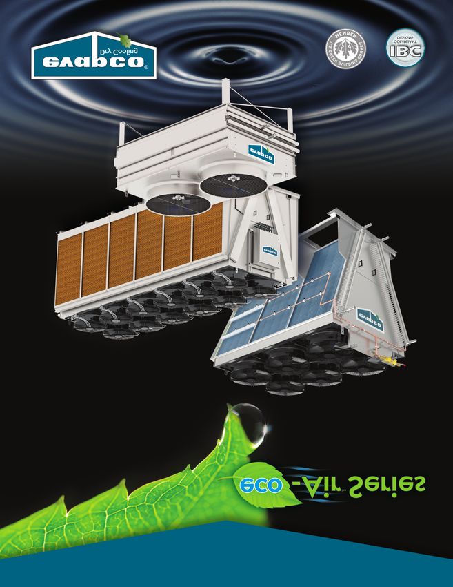
Our latest heat transfer solutions are the eco-Air™ Series Dry Coolers, eco-Air Series Air Cooled Condensers,
eco-Air Series Adiabatic Coolers and Condensers, and eco-Air Series Spray Coolers and Condensers. The eco-Air
Series completes our successful eco-family of closed circuit coolers and condensers with water-saving dry and
hybrid technology.
As an industry leader in independent, third-party performance certifications, our fully-rated products enable you to
operate your cooling systems efficiently and with complete peace of mind.
The eco-Air Series coolers offers unparalleled flexibility in a wide range of capacities, footprints, motor types, and
control options.
EC Motor Option NEMA Motor Option
EC & NEMA Motor Options Available on
Flat (EAFWD), V Coil Dry (EAVWD),
V Coil Adiabatic (EAVWA) and V Coil Spray (EAVWS) Models
3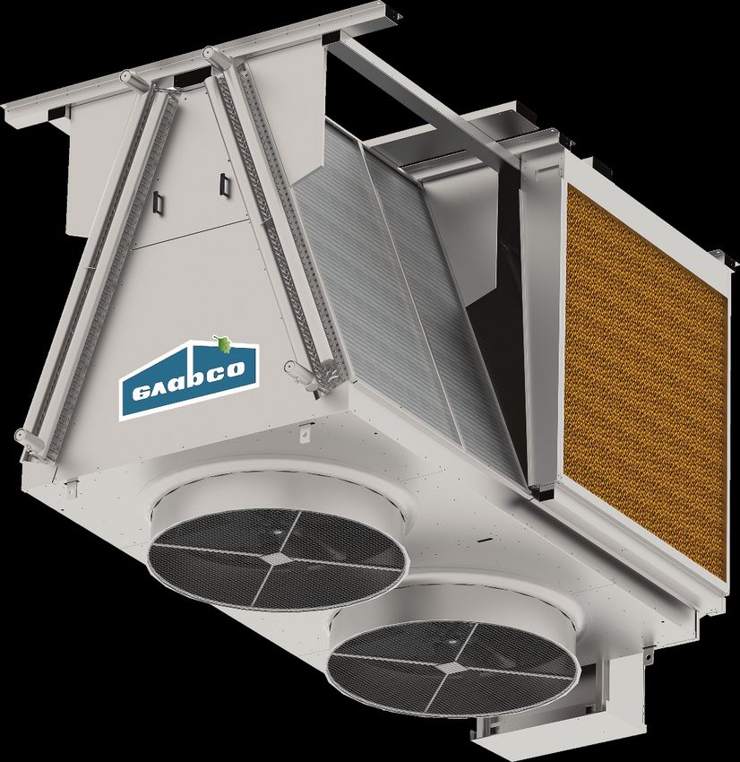
eco-Air Series Design & Construction Features

The eco-Air Series of dry coolers represents EVAPCO’s newest advancement in thermal heat transfer
research and development. Available in fully dry, adiabatic and spray designs, the eco-Air Series maximizes
heat rejection with minimal or no water use. The eco-Air Series is another chapter in EVAPCO’s ongoing
commitment to high quality, environmentally friendly products.

Structure and Casing
• Type 304L Stainless Steel as                       V Coil Models
  standard for increased corrosion                              • Maximum surface area per footprint
  resistance and longevity                                      • Optimized coil angle for heat rejection
• G-235 galvanized steel                                          and air flow
  available (Dry &                                              • Compact plan area and layout
  Adiabatic Models
  only)

                                                                                                                      Epoxy Coated Fins
                                                     Adiabatic Pre-Cooling             Spray Assist                   • Standard on Spray
                                                     System (Optional)                 System (Optional)                Models
Inspection Panel             Heat Exchanger          • Wetted pads can be utilized     • Peak load cooling solution   • Optional on Dry &
 (V Coil Models)             Coils                     to pre-cool entering air,       • Epoxy Coated Fins              Adiabatic Models
• Easily removable for       • Type 304L               resulting in greater energy     • Tangential-flow hollow       • Increased corrosion
   interior inspection and     Stainless Steel         savings, and increased            cone nozzles                   resistance
   access to coils and fan     tubes with              capacity, with minimal          • Self-draining                • No impact on unit
   motors                      aluminum fins           water use                         copper piping                  capacity
                             • Multiple fin          • Great for high dry bulb
                               spacings and tube       climates and high
                               configurations          temperature applications
                             • Upgraded fin          • Once through design
                               thickness available   • No water treatment required
                                                     • No cold water basin or pump
                                                     • No drift
                                                     • V coil models only                Coil Return
                                                                                         Bend Covers
                                                                                         • Protects the coil
                                              Internal Step Deck                           return bends
                                              (Optional-V Coil Models)                     during handling
                                              • Platform and grab rail for access to       and operation
                                                elevated fan section components
                                                (7’ 9.75” wide V Coil Models only)

4
eco-Air Series Design & Construction Features

Advanced Motor Technology – Electronically Commutated (EC) or NEMA fan motor designs

                                   EC                                                               NEMA
                                   •   High Efficiency                                              • Premium efficient direct drive
                                   •   Zero Maintenance                                             • Zero maintenance permanently
                                   •   Integral Speed Control                                         sealed bearings
                                   •   Inherently Low Sound                                         • VFD ready
                                                                                                    • Severe Duty

                                                                                                 Common Terminal Box
Flat Coil Models                                                                                 • All motors factory wired
                                                                                                 • Saves time in the field
• Low profile design
                                                                                                 • UL Recognized
• Great for elevated
  installations with
  bottom airflow
  clearance

                                                                             Easy Rigging
                                                                             • All units are
                                                                               designed for
                                                                               lifting as once   Factory Mounted &
                                                                               piece             Wired Controls
                                                           Fork Lift Channels                    • EVAPCO PLC Panel
                                                           • V and Flat units up to                (EC Motors)
                                                             27 ft in length                     • EVAPCO PLC/VFD Panel
                                                                                                   (NEMA Motors)
                                          Multiple Leg                                           • Single point power connection
                                          Heights Available                                      • UL & cUL Listed
                                          (Flat Coil Models)                                     • UL Type 4 enclosure

             Coils Pressurized with Nitrogen
             • Limits internal corrosion potential during transport and storage

                 IBC Compliant Design
                 • All standard models meet IBC requirements
                 • Upgraded designs available for high seismic and wind load areas
                 • Shake table verified for 1.5 Importance Factor installations

               Warranty
               • 2 years complete unit
               • 2 years adiabatic pads (if equipped)
               • 2 years spray system (if equipped)
               • 1 year EVAPCO Controller and other
                 electrical components (if equipped)

                                                                                                                                   5
Dry Principle of Operation

    eco-Air Series V Coil (EAVWD) & Flat Coil (EAFWD) Air Cooled Cooler
    Hot Process fluid enters the inlet header connection, shown in red. Heat from the fluid dissipates through the coil
    tubes surface and out to the fins. Ambient air is drawn in over the coil surface by the fan located at the top of the unit.
    Heat from the process fluid transfers to the air and discharges to the atmosphere. Cool process fluid exits the unit
    through the connections shown in blue.

                                                                   Hot Dry Discharge Air

                                      Hot Fluid                                                            Hot Fluid
                                         In                                                                   In

                                                  Cool Dry                                      Cool Dry
                                                  Entering                                      Entering
                                                     Air                                           Air

                                           Cool Fluid                                               Cool Fluid
                                             Out                                                      Out

                                                                  Hot Dry Discharge Air

                                                                                                            Hot Fluid
                                                                                                               In
                                  Cool Fluid
                                    Out

                                                          Cool Dry                    Cool Dry
                                                         Entering Air                Entering Air

6
Adiabatic & Spray Principle of Operation

eco-Air Series V Coil (EAVWA) Adiabatic Cooler
Hot process fluid enters the inlet header connection, shown in red. Heat from the process fluid dissipates through the coil
tubes surface and out to the fins. The adiabatic system involves fully wetting a fibrous pad located in front of the coil.
Ambient air is drawn through the adiabatic pre-cooling pad by the fans located on top of the unit. The air is saturated as it
passes through the adiabatic pad, decreasing the dry bulb temperature within a few degrees of the wet bulb temperature.
This new air temperature is referred to as the depressed dry bulb. This pre-cooled air is then drawn through the tube and fin
surface, offering a substantial increase in heat rejection capability. Heat from the process fluid transfers to the air and
discharged to the atmosphere. Cool process fluid exits the unit through the connections shown in blue.
                                                             Hot Discharge Air

                                      Hot Fluid                                               Hot Fluid
                                         In                                                      In

                                          Cool Dry                                        Cool Dry
                                          Entering                                        Entering
                                             Air                                             Air

                                 Pre-Cooled Air                                              Pre-Cooled Air
                               (Depressed Dry Bulb)                                        (Depressed Dry Bulb)
                                      Wetted                                                 Wetted
                                    Adiabatic Pad                                          Adiabatic Pad
                                      Cool Fluid                                              Cool Fluid
                                        Out                                                     Out

eco-Air Series V Coil (EAVWS) Spray Cooler
Hot process fluid enters the inlet header connection, shown in red. Heat from the process fluid dissipates through the coil
tubes surface and out to the fins. The unit operates completely dry and modulates fan speed as necessary based on
process temperature requirements and ambient conditions. When the unit can no longer maintain leaving water
temperature set point in dry mode, the spray assist system is actuated. The spray system nozzles spray water away from the
coil, cooling the entering air and increasing the heat rejection capability of the unit. The heat from the process fluid
transfers to the cooled air and is discharged to the atmosphere. Cool process fluid exits the unit through the connections
shown in blue.
                                                                                 Hot Dry Discharge Air

   Spray System Disclaimer: Although the
   nozzles spray water away from the coil, the
   coil and structure will get wet when water is
   in use. Due to this, the water chemistry                Hot Fluid                                                   Hot Fluid
                                                              In                                                          In
   guidelines provided in the Installation and
   Operation Manual should be strictly
   followed along with the recommended                  Dry                                                                      Dry
   cleaning and maintenance instructions.             Entering      Pre-Cooled                               Pre-Cooled        Entering
                                                        Air             Air                                      Air             Air
   Evapco also recommends designing the
   system for a maximum of 200 hours of
   spray operation per year to help limit the
   possibility for scale build-up and corrosion.                    Spray                                          Spray
                                                                   Nozzles                                        Nozzles

                                                                 Cool Fluid                                       Cool Fluid
                                                                   Out                                              Out

                                                                                                                                          7
Advanced Coil Technology

    EVAPCO has long been the industry innovator in heat exchanger coil technology starting in the early 1990's with
    the introduction of Thermal-Pak® coils which revolutionized the industry. Soon after, EVAPCO became the
    benchmark in industrial evaporator design, standardizing on stainless steel tubes and aluminum fins. The eco-Air
    Series coil design builds upon this past success. The coil tube diameter, geometry, and circuiting have been
    optimized through thousands of hours of theoretical modeling and laboratory testing. The result is optimal heat
    transfer efficiency with low airside pressure drop and low motor horsepower per ton.

    Coil Design
    Through the use of computational fluid dynamics (CFD) modeling software, finite element heat transfer analysis,
    and proprietary coil performance calculation methods, EVAPCO engineers have identified significant design
    elements to improve the finned coil performance. The extensive computer modeling has been refined and
    verified through coil performance evaluation in EVAPCO's state of the art research laboratories.

    Superior Stainless Steel Technology
    eco-Air Series dry coolers are constructed with high-grade Type 304L stainless steel tubing and aluminum fins as
    standard. The stainless steel tubing meets the requirements of ASME B31.5 piping code. The tubing is roll formed
    and continuously welded, annealed, and tested using an eddy current device.
    The round tubing is fit into the aluminum fin plate and hydraulically expanded, this procedure provides more
    consistent contact between the tube and the fin plate than mechanical expansion. The entire coil is then pressure
    tested to 110% of design working pressure. Lastly, the coil is dried, evacuated, and charged with low-pressure
    nitrogen prior to shipment.
    EVAPCO’s stainless steel tubes are available in 5/8-inch OD. Coils are built in 6, 8, 10 or 12 FPI as standard using
    a full-collar aluminum fin. Multiple fin thicknesses are available to accommodate a range of industrial
    applications.
    For applications where corrosion of the aluminum fin is a concern, EVAPCO offers pre-coated epoxy fin stock.

8
Benefits of eco-Air Series

Reduced Maintenance
Scaling, corrosion, and water born bacteria concerns are minimized or
eliminated with dry and adiabatic cooling equipment. The eco-Air
Series reduces the maintenance traditionally associated with fully
evaporative systems.
The eco-Air Series adiabatic & spray coolers are designed as a once
through systems, meaning no pump and no basin to hold water,
reducing the time required for maintenance. Additionally on adiabatic
units, the adiabatic pads filter the air before reaching the coil, limiting
                                                                                         Adiabatic Pad Drip Pan
the exposure of dirt and debris to the tube and fin heat transfer surface.
Both NEMA and EC motor options require zero routine maintenance.
There are no bearings to grease, belts to adjust, or fans to pitch and
balance.

Reduced or Eliminated Water Consumption
Compared to traditional evaporative systems, the eco-Air Series will
either eliminate or dramatically reduce water consumption. Adiabatic &
spray models only use water when the ambient conditions and load
require it. Reducing water consumption also reduces the ongoing
expenses related with the cooling equipment such as purchasing, treating,               Zero Maintenance Motors
and disposing of water.
When the eco-Air Series adiabatic & spray models are used in conjunction with the EVAPCO controls package,
water conservation is maximized based on proprietary PLC logic.

Factory Mounted and Wired Controls
The motors on the eco-Air Series are pre-wired at
the factory to UL standards, reducing costs
associated with field wiring. As standard, all units
are wired to a common terminal box. Adding the
EVAPCO controls package allows for both single
point power supply and complete
capacity control.

Installation Made Easy
All units are designed for lifting and staging
in one piece.
                                                                                                   Factory Mounted
Fork lift channels come standard on all                                                              Control Panel
eco-Air Series units up to 27 feet in length.
On longer units, reference the eco-Air
Series IO&M for lifting requirements from
the fan deck lifting lugs.
                                                             Factory Wired Fan Motors

                                                                                                                     9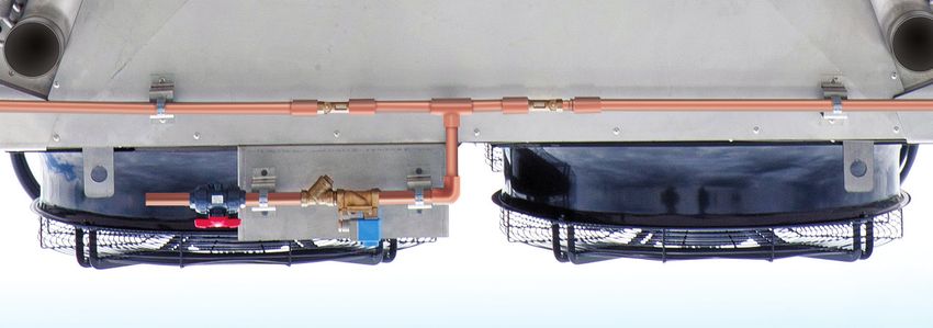
V Coil Configuration - EC Motor

 Engineering Data

                 *4' 2-1/8"                           A                 A             A                    A            A               A

                                 (2) INLETS

(2) INSPECTION                                                                                                                                       5' 9-7/8"
     PANEL

                                (2) OUTLETS

                                                                                                L

 Single Fan, 4' Wide Models
                                        Nominal Capacity       HP           Air Volume     Unit Length    Coil Volume    Shipping           Operating
       Model Name             # Fans       (MBH)†             (kW)             (cfm)            (L)           (gal.)    Weight (lbs.)       Weight (lbs.)

      EAVWD91S1MJ               1              242          4.3 (3.2)         17670        5' - 3-3/8"         33           1660               1940
      EAVWD91S2MJ               2              484          8.6 (6.4)        35340        9' - 6-5/8"          52           2810               3250
      EAVWD91S3MJ               3              730         12.9 (9.6)        53010        13' - 9-3/4"         70           3980               4570
      EAVWD91S4MJ               4              967         17.2 (12.8)       70680          18' - 0"           89           5180               5930
      EAVWD91S5MJ               5              1203         21.5 (16)        88350        22' - 4-1/8"         108          6390               7290
      EAVWD91S6MJ               6              1456        25.7 (19.1)       106020       26' - 7-3/8"         126          7550               8610
      EAVWD91S7MJ               7              1671        30 (22.3)         123690       30' - 10-1/2"        145          8630               9840
      EAVWD91S8MJ               8              1923        34.3 (25.5)       141360       35' - 1-3/4"         163          9800               11160
      EAVWD91S9MJ               9              2174        38.6 (28.7)       159030       39' - 4-7/8"         182          10940             12460
    EAVWD91S0MA                10              2298        42.9 (31.9)       170447       39' - 4-7/8"         182          11210              12730

 Notes:
 * Adiabatic width: 5’ 10-1/8”
 A: Two incremental fin lengths available: 3' 10-1/16" or 4' 3-3/16"
 Dimensions are subject to change. Do not use for pre-fabrication.
 † Nominal Capacity 110°F-100°F at 92°F dry bulb temp.
 Adiabatic capacity: The adiabatic cooling effect and resulting depressed dry bulb entering the coil depends on the ambient dry bulb and associated
 relative humidity. Consult your sales representative, EVAPCO marketing, or Spectrum™ selection software for more information.
 Spray Capacity: The cooling effect resulting from operating the spray system depends on the ambient dry bulb and associated relative humidity
 entering the coil. Consult your sales representative, EVAPCO marketing or Spectrum™ selection software for more information.

 10
V Coil Configuration - EC Motor
Engineering Data
*7' 2-1/2"
A A A A A A
(2) INLETS
(2) INSPECTION
PANEL 7' 11"
(2) OUTLETS
L
Twin Fan, 7' Wide Models
Nominal Capacity HP Air Volume Unit Length Coil Volume Shipping Operating
Model Name # Fans (MBH)† (kW) (cfm) (L) (gal.) Weight (lbs.) Weight (lbs.)
EAVWD9102PJ 2 425 8.6 (6.4) 31976 5' - 3-3/8" 51 2610 3040
EAVWD9104PJ 4 848 17.2 (12.8) 63951 9' - 6-5/8" 80 4390 5060
EAVWD9106PJ 6 1278 25.7 (19.1) 95927 13' - 9-3/4" 108 6180 7090
EAVWD9108PJ 8 1692 34.3 (25.5) 127902 18' - 0" 137 8020 9160
EAVWD9110PJ 10 2104 42.9 (31.9) 159878 22' - 4-1/8" 165 9860 11240
EAVWD9112PJ 12 2547 51.5 (38.3) 191853 26' - 7-3/8" 194 11640 13260
EAVWD9114PJ 14 2923 60.1 (44.7) 223829 30' - 10-1/2" 223 13290 15150
EAVWD9116PJ 16 3363 68.7 (51.1) 255804 35' - 1-3/4" 251 15080 17180
EAVWD9118PJ 18 3804 77.2 (57.5) 287780 39' - 4-7/8" 280 16850 19180
EAVWD9120PA 20 3971 85.8 (63.9) 304120 39' - 4-7/8" 280 17310 19640
Notes:
* Adiabatic width: 8’ 9-5/8”
A: Two incremental fin lengths available: 3' 10-1/16" or 4' 3-3/16"
Dimensions are subject to change. Do not use for pre-fabrication.
† Nominal Capacity 110°F-100°F at 92°F dry bulb temp.
Adiabatic capacity: The adiabatic cooling effect and resulting depressed dry bulb entering the coil depends on the ambient dry bulb and associated
relative humidity. Consult your sales representative, EVAPCO marketing, or Spectrum™ selection software for more information.
Spray Capacity: The cooling effect resulting from operating the spray system depends on the ambient dry bulb and associated relative humidity
entering the coil. Consult your sales representative, EVAPCO marketing or Spectrum™ selection software for more information.
11V Coil Configuration - EC Motor
Engineering Data
A A A A A A
*7' 9-7/8"
(2) INLETS
(2) INSPECTION 9' 5-1/2"
PANEL
(2) OUTLETS
L
Twin Fan, 8' Wide Models
Nominal Capacity HP Air Volume Unit Length Coil Volume Shipping Operating
Model Name # Fans (MBH)† (kW) (cfm) (L) (gal.) Weight (lbs.) Weight (lbs.)
EAVWD9102ZJ 2 496 8.6 (6.4) 35762 5' - 3-3/8" 69 3050 3630
EAVWD9104ZJ 4 992 17.2 (12.8) 71525 9' - 6-5/8" 107 5150 6050
EAVWD9106ZJ 6 1486 25.7 (19.1) 107287 13' - 9-3/4" 146 7270 8490
EAVWD9108ZJ 8 1978 34.3 (25.5) 143050 18' - 0" 185 9420 10960
EAVWD9110ZJ 10 2482 42.9 (31.9) 178812 22' - 4-1/8" 223 11580 13440
EAVWD9112ZJ 12 2960 51.5 (38.3) 214574 26' - 7-3/8" 262 13680 15870
EAVWD9114ZJ 14 3401 60.1 (44.7) 250337 30' - 10-1/2" 300 15620 18130
EAVWD9116ZJ 16 3912 68.7 (51.1) 286099 35' - 1-3/4" 339 17730 20560
EAVWD9118ZA 18 4194 77.2 (57.5) 310953 35' - 6-7/8" 378 19820 22970
EAVWD9120ZA 20 4680 85.8 (63.9) 345503 39' - 4-7/8" 378 20310 23460
Notes:
* Adiabatic width: 9’ 7/8”
A: Two incremental fin lengths available: 3' 10-1/16" or 4' 3-3/16"
Dimensions are subject to change. Do not use for pre-fabrication.
† Nominal Capacity 110°F-100°F at 92°F dry bulb temp.
Adiabatic capacity: The adiabatic cooling effect and resulting depressed dry bulb entering the coil depends on the ambient dry bulb and associated
relative humidity. Consult your sales representative, EVAPCO marketing, or Spectrum™ selection software for more information.
Spray Capacity: The cooling effect resulting from operating the spray system depends on the ambient dry bulb and associated relative humidity
entering the coil. Consult your sales representative, EVAPCO marketing or Spectrum™ selection software for more information.
12V Coil Configuration - NEMA Motor
Engineering Data
*7' 2-1/2"
A A A A
(2) INLETS
(2) INSPECTION 7' 11-1/2"
PANEL
(2) OUTLETS
L
Single Fan, 7' Wide Models
Nominal Capacity HP Air Volume Unit Length Coil Volume Shipping Operating
Model Name # Fans (MBH)† (kW) (cfm) (L) (gal.) Weight (lbs.) Weight (lbs.)
EAVWD15S1PI 1 601 10 (7.5) 43020 8' - 8-3/8" 74 4110 4730
EAVWD15S2PI 2 1212 20 (15) 85830 16' - 4-1/2" 125 7370 8420
EAVWD15S3PI 3 1828 30 (22.5) 128850 24' - 5/8" 177 10720 12200
EAVWD15S4PI 4 2384 40 (30) 171860 31' - 8-3/4" 228 13790 15700
EAVWD15S5PI 5 3011 50 (37.5) 214670 39' - 4-7/8" 280 17110 19430
EAVWD15S6PK 6 3284 60 (45) 239040 39' - 4-7/8" 280 17790 20120
Notes:
* Adiabatic width: 8’ 9-5/8”
A: Three incremental fin lengths available: 5' 9-1/16", 6' 4-3/4" or 7' 8-1/8"
Dimensions are subject to change. Do not use for pre-fabrication.
† Nominal Capacity 110°F-100°F at 92°F dry bulb temp. Adiabatic = dry bulb 102°F
Adiabatic capacity: The adiabatic cooling effect and resulting depressed dry bulb entering the coil depends on the ambient dry bulb and associated
relative humidity. Consult your sales representative, EVAPCO marketing, or Spectrum™ selection software for more information.
Spray Capacity: The cooling effect resulting from operating the spray system depends on the ambient dry bulb and associated relative humidity
entering the coil. Consult your sales representative, EVAPCO marketing or Spectrum™ selection software for more information.
13V Coil Configuration - NEMA Motor
Engineering Data
A A A A
*7' 9-7/8"
(2) INLETS
9' 6"
(2) INSPECTION
PANEL
(2) OUTLETS
L
Single Fan, 8' Wide Models
Nominal Capacity HP Air Volume Unit Length Coil Volume Shipping Operating
Model Name # Fans (MBH)† (kW) (cfm) (L) (gal.) Weight (lbs.) Weight (lbs.)
EAVWD15S1ZI 1 696 10 (7.5) 47260 8' - 8-3/8" 100 4810 5650
EAVWD15S2ZI 2 1391 20 (15) 94520 16' - 4-1/2" 169 8630 10040
EAVWD15S3ZI 3 2083 30 (22.5) 141770 24' - 5/8" 239 12540 14530
EAVWD15S4ZI 4 2773 40 (30) 188820 31' - 8-3/4" 308 16160 18730
EAVWD15S5ZI 5 3432 50 (37.5) 236070 39' - 4-7/8" 378 20030 23180
EAVWD15S6ZK 6 3822 60 (45) 268920 39' - 4-7/8" 378 20750 23900
Notes:
* Adiabatic width: 9’ 7/8”
A: Two incremental fin lengths available: 5' 9-1/16", 6' 4-3/4" or 7' 8-1/8"
Dimensions are subject to change. Do not use for pre-fabrication.
† Nominal Capacity 110°F-100°F at 92°F dry bulb temp.
Adiabatic capacity: The adiabatic cooling effect and resulting depressed dry bulb entering the coil depends on the ambient dry bulb and associated
relative humidity. Consult your sales representative, EVAPCO marketing, or Spectrum™ selection software for more information.
Spray Capacity: The cooling effect resulting from operating the spray system depends on the ambient dry bulb and associated relative humidity
entering the coil. Consult your sales representative, EVAPCO marketing or Spectrum™ selection software for more information.
14Flat Coil Configuration - EC Motor
Engineering Data
5' 10-5/8" 6' 4-3/4" 6' 4-3/4" 6' 4-3/4" 6' 4-3/4"
INLET
6' 8"
OUTLET
L 3-3/8"
Single Fan, 6' Wide Models
Nominal Capacity HP Air Volume Unit Length Coil Volume Shipping Operating
Model Name # Fans (MBH)† (kW) (cfm) (L) (gal.) Weight (lbs.) Weight (lbs.)
EAFWD91S1WK 1 258 4.3 (3.2) 18423 6' - 8-1/4" 33 1800 2080
EAFWD91S2WK 2 518 8.6 (6.4) 36845 13' - 0" 54 3120 3580
EAFWD91S3WK 3 775 12.9 (9.6) 55268 19' - 5-3/4" 76 4500 5130
EAFWD91S4WK 4 1032 17.2 (12.8) 73690 25' - 10-1/2" 97 5790 6600
EAFWD91S5WK 5 1274 21.5 (16) 92113 32' - 3-1/4" 118 7000 7990
EAFWD91S6WK 6 1541 25.7 (19.1) 110536 38' - 8" 140 8320 9490
Notes:
Dimensions are subject to change. Do not use for pre-fabrication.
† Nominal Capacity based on 110°F-100°F at 92°F dry bulb temperature.
15Flat Coil Configuration - EC Motor
Engineering Data
7' 2-3/8"
A A A A
INLET
7' 1"
OUTLET
L 3-3/8"
Twin Fan, 7' Wide Models
Nominal Capacity HP Air Volume Unit Length Coil Volume Shipping Operating
Model Name # Fans (MBH)† (kW) (cfm) (L) (gal.) Weight (lbs.) Weight (lbs.)
EAFWD9102PI 2 443 8.6 (6.4) 33060 7' - 11-1/2" 44 2420 2790
EAFWD9104PI 4 878 17.2 (12.8) 66121 15' - 7-5/8" 75 4320 4950
EAFWD9106PI 6 1322 25.7 (19.1) 99181 23' - 3-3/4" 106 6210 7100
EAFWD9108PI 8 1746 34.3 (25.5) 132241 30' - 11-7/8" 137 7940 9090
EAFWD9110PI 10 2206 42.9 (31.9) 165301 38' - 8" 168 9830 11230
EAFWD9112PK 12 2258 51.5 (38.3) 182472 38' - 8" 168 10160 11560
Notes:
A: Two incremental fin lengths available: 6' 4-3/4" or 7' 8-1/8"
Dimensions are subject to change. Do not use for pre-fabrication.
† Nominal Capacity based on 110°F-100°F at 92°F dry bulb temperature.
16Flat Coil Configuration - EC Motor
Engineering Data
7' 10-1/4" A A A A
INLET
7' 1"
OUTLET
L 3-3/8
Twin Fan, 8' Wide Models
Nominal Capacity HP Air Volume Unit Length Coil Volume Shipping Operating
Model Name # Fans (MBH)† (kW) (cfm) (L) (gal.) Weight (lbs.) Weight (lbs.)
EAFWD9102ZI 2 470 8.6 (6.4) 34550 7' - 11-1/2" 50 2630 3050
EAFWD9104ZI 4 938 17.2 (12.8) 69101 15' - 7-5/8" 85 4690 5400
EAFWD9106ZI 6 1403 25.7 (19.1) 103651 23' - 3-3/4" 119 6740 7740
EAFWD9108ZI 8 1853 34.3 (25.5) 138201 30' - 11-7/8" 154 8610 9900
EAFWD9110ZI 10 2340 42.9 (31.9) 172752 38' - 8" 189 10660 12240
EAFWD9112ZK 12 2553 51.5 (38.3) 192943 38' - 8" 189 11000 12580
Notes:
A: Two incremental fin lengths available: 6' 4-3/4" or 7' 8-1/8"
Dimensions are subject to change. Do not use for pre-fabrication.
† Nominal Capacity based on 110°F-100°F at 92°F dry bulb temperature.
17Flat Coil Configuration - NEMA Motor
Engineering Data
7' 2-3/8"
A A A A
INLET
7' 1-7/8"
OUTLET
L 3-3/8"
Single Fan, 7' Wide Models
Nominal Capacity HP Air Volume Unit Length Coil Volume Shipping Operating
Model Name # Fans (MBH)† (kW) (cfm) (L) (gal.) Weight (lbs.) Weight (lbs.)
EAFWD15S1PI 1 446 10 (7.5) 33360 7' - 11-1/2" 44 2740 3110
EAFWD15S2PI 2 884 20 (15) 66760 15' - 7-5/8" 75 4940 5570
EAFWD15S3PI 3 1331 30 (22.5) 100030 23' - 3-3/4" 106 7140 8030
EAFWD15S4PI 4 1758 40 (30) 133510 30' - 11-7/8" 137 9180 10330
EAFWD15S5PI 5 2220 50 (37.5) 166780 38' - 8" 168 11380 12780
EAFWD15S6PK 6 2331 60 (45) 177370 38' - 8" 168 11920 13320
Notes:
A: Three incremental fin lengths available: 5' 9-1/16", 6' 4-3/4" or 7' 8-1/8"
Dimensions are subject to change. Do not use for pre-fabrication.
† Nominal Capacity based on 110°F-100°F at 92°F dry bulb temperature.
18Flat Coil Configuration - NEMA Motor
Engineering Data
7' 10-1/4" A A A A
INLET
7' 1-7/8"
OUTLET
L 3-3/8"
Single Fan, 8' Wide Models
Nominal Capacity HP Air Volume Unit Length Coil Volume Shipping Operating
Model Name # Fans (MBH)† (kW) (cfm) (L) (gal.) Weight (lbs.) Weight (lbs.)
EAFWD15S1ZI 1 483 10 (7.5) 35820 7' - 11-1/2" 50 2940 3360
EAFWD15S2ZI 2 964 20 (15) 71420 15' - 7-5/8" 85 5300 6010
EAFWD15S3ZI 3 1441 30 (22.5) 107230 23' - 3-3/4" 119 7660 8660
EAFWD15S4ZI 4 1903 40 (30) 143040 30' - 11-7/8" 154 9840 11130
EAFWD15S5ZI 5 2405 50 (37.5) 178640 38' - 8" 189 12200 13780
EAFWD15S6ZK 6 2538 60 (45) 199060 38' - 8" 189 13250 14830
Notes:
A: Three incremental fin lengths available: 5' 9-1/16", 6' 4-3/4" or 7' 8-1/8"
Dimensions are subject to change.
† Nominal Capacity based on 110°F-100°F at 92°F dry bulb temperature.
19Wiring and Control Options
Factory wiring and control options are available for all eco-Air Series coolers. All wiring follows UL recognized
standards. Many eco-Air Series configurations allow for single point power and factory mounted components.
Please consult your sales representative or EVAPCO Marketing for job specific details.
Common Terminal Box (standard) - All motors wired to a common terminal box located on the end panel opposite coil
connections. Factory wiring and design complies with UL Recognized Standards.
Individual Motor Disconnect Switches (optional) - Mounted at each fan motor to give the user the ability to isolate
individual motor power feeds.
20Wiring and Control Options
EVAPCO Control Package – Operating sequence and fan speed control based on real time heat loads and
ambient conditions.
-• EVAPCO PLC Controller
• Supervisory control system integration
• Fan speed control
– EC Motor Option: Modbus control of EC fan
– NEMA Motor Option: Packaged VFD fan speed control
with bypass switch
• UL Listed
• UL Type 4 enclosure
• Thermal overload and short circuit protection of each motor
• Operate and fault indicator lights on outside of panel
• Fluid Temperature Sensor (shipped loose)
• Ambient Temperature Sensor
• Rain/Sun Protection Hood (optional)
• Solenoid control of adiabatic pre-cooling system (if equipped)
Solenoid Control of
Adiabatic Pre-cooling
& Spray Systems
(if equipped)
Water supply solenoid valve arrangement
The EVAPCO Control Package is factory mounted and wired when configuration and shipping limitations allow.
UL (cUL) Compliance
All Components are
UL Recognized
The entire unit is UL
Listed when provided
with factory mounted
and wired EVAPCO
Control Package.
21Structural Steel Support
eco-Air Series Supporting Steel Dimensions
V Models Dry & Spray Unit Base Width (W) Adiabatic Unit Base Width (W)
4’ Wide 4’ 2” 5’ 10”
7’ Wide 7’ 2-1/2” 8’ 9-1/2”
8’ Wide 7’ 3-3/4” 9’ 3/4”
F Models Base Width (W) –
6’ Wide 5’ 7-5/16” –
7’ Wide 6’ 11-1/8” –
8’ Wide 7’ 7” –
Base Width (W) Length (L)
Length as shown on "unit length range (L)" in catalog table
1. These are suggested arrangements for preliminary layout purposes. Consult your EVAPCO representative for factory certified steel
support drawings.
2. The recommended support for the eco-Air Series coolers is structural I-beams running the entire length of the unit. Mounting holes,
3/4” in diameter are provided for bolting to the structural steel.
3. Beams should be sized in accordance with accepted structural practices. Maximum deflection of beam under unit to be 1/360 of the
unit length, not to exceed 1/2”.
5. Beams should be level before setting the unit in place. Do not level the unit by shimming between it and the I-beams.
6. Support beams and Anchor bolts are to be furnished by others.
7. Dimensions, weights and data are subject to change without notice. Refer to the factory certified drawings for exact dimensions.
22EVAPCO Technical Support Services
EVAPCO Representatives
Your EVAPCO representative is the local expert you can count on to help you with all your HVAC and industrial
process needs—from getting quotes, to answering questions, to helping you manage your projects and orders.
Find your local representative, by visiting evapco.com now.
SPECTRUM™ by EVAPCO
SPECTRUM™ is a new industry leading computer selection program that
makes it easy for you to find and optimize the right EVAPCO solutions for
every project. Evaluate thermal performance, layout, and energy
requirements across units; analyze optional equipment features; and generate complete specifications and unit
drawings—all within a friendly and intuitive format. Contact your EVAPCO representative to access
SPECTRUM™ now.
evapco.com
Bookmark evapco.com for the latest and most complete product information. The website contains a multitude
of information and resources including:
• Unit certified drawings • Rigging instructions
• Steel support drawings • Operation and maintenance instructions
• Scaled isometric views in CAD • White papers
• 3-D models in Revit • Videos
• Product catalogs • Logo apparel and merchandise
23OUR PRODUCTS ARE MANUFACTURED WORLDWIDE.
Wo Headquarters/
World
Re
Research and
De
Development Center
EVAPCO Facilities
EVAPCO, Inc. — World Headquarters & Research / Development Center
P.O. Box 1300 • Westminster, MD 21158 USA
410-756-2600 p • marketing@evapco.com • evapco.com
North America Europe Asia/Pacific
EVAPCO, Inc. EVAPCO Europe BVBA EVAPCO Asia/Pacific Headquarters
World Headquarters European Headquarters 1159 Luoning Road
Heersterveldweg 19 Baoshan Industrial Zone
P.O. Box 1300 EVAPCO Dry Cooling Industrieterrein Oost Shanghai 200949, P.R. China
Westminster, MD 21158 USA Bridgewater, NJ 08807 USA 3700 Tongeren, Belgium (86) 21-6687-7786 p
410-756-2600 p | 410-756-6450 f 1-908-379-2665 p (32) 12-395029 p | (32) 12-238527 f (86) 21-6687-7008 f
marketing@evapco.com info@evapcodc.com evapco.europe@evapco.be marketing@evapcochina.com
EVAPCO Dry Cooling
EVAPCO East Littleton, CO 80127 USA EVAPCO Europe, S.r.l. EVAPCO (Shanghai) Refrigeration Equipment Co., Ltd.
5151 Allendale Lane 1-908-379-2665 p Milan, Italy Baoshan Industrial Zone Shanghai, P.R. China
Taneytown, MD 21787 USA info@evapcodc.com (39) 02-939-9041 p (86) 21-6687-7786 p
410-756-2600 p | 410-756-6450 f Spare Parts: 908-895-3236 evapcoeurope@evapco.it marketing@evapcochina.com
marketing@evapco.com Spare Partsl: spares@evapcodc.com
EVAPCO Europe, S.r.l. Beijing EVAPCO Refrigeration Equipment Co., Ltd.
EVAPCO East EVAPCO Power México S. de R.L. de C.V. Sondrio, Italy Huairou District Beijing, P.R. China
Key Building Calle Iglesia No. 2, Torre E 010-6166-7238 p
Taneytown, MD USA EVAPCO Europe GmbH evapcobj@evapcochina.com
Tizapan San Ángel, Del. Álvaro Obregón Meerbusch, Germany
410-756-2600 p Ciudad de México, D.F. México 01090
marketing@evapco.com (49) 2159 6956 18 p EVAPCO Air Cooling Systems (Jiaxing) Company, Ltd.
Phone: +52 (55) 8421-9260 info@evapco.de
e-mail: info@evapcodc.com 1288 Kanghe Road,
EVAPCO Midwest Xiuzhou district, Jiaxing, Zhejiang, China
Greenup, IL USA EVAPCO Air Solutions
Refrigeration Vessels & Systems Corporation A wholly owned subsidiary of EVAPCO, Inc. info@evapcoacs.cn
217-923-3431 p
evapcomw@evapcomw.com A wholly owned subsidiary of EVAPCO, Inc. Aabybro, Denmark
Bryan, TX USA (45) 9824 4999 p EVAPCO Australia (Pty.) Ltd.
979-778-0095 p info@evapco.dk Riverstone NSW 2765, Australia
EVAPCO West (61) 2 9627-3322 p
Madera, CA USA rvs@rvscorp.com
EVAPCO Air Solutions GmbH sales@evapco.com.au
559-673-2207 p
contact@evapcowest.com EvapTech, Inc. Garbsen, Germany
A wholly owned subsidiary of EVAPCO, Inc. (49) 5137 93875-0 p EVAPCO Composites Sdn. Bhd
EVAPCO Iowa Edwardsville , KS USA info@evapcoas.de Rawang, Selangor, Malaysia
Lake View, IA USA 913-322-5165 p (60-3) 6092-2209 p
712-657-3223 p marketing@evaptech.com Evap Egypt Engineering Industries Co.
A licensed manufacturer of EVAPCO, Inc. EvapTech Asia Pacific Sdn. Bhd
EVAPCO Iowa Nasr City, Cairo, Egypt A wholly owned subsidiary of EvapTech, Inc.
Tower Components, Inc. 2 02 24022866/2 02 24044997 p
Sales & Engineering A wholly owned subsidiary of EVAPCO, Inc.
Puchong, Selangor, Malaysia
Medford, MN USA primacool@link.net / shady@primacool.net (60-3) 8070-7255 p
Ramseur, NC USA
507-446-8005 p marketing-ap@evaptech.com
336-824-2102 p EVAPCO S.A. (Pty.) Ltd.
evapcomn@evapcomn.com mail@towercomponentsinc.com A licensed manufacturer of EVAPCO, Inc.
EVAPCO Newton
Isando 1600, Republic of South Africa South America
EVAPCO Alcoil, Inc. (27) 11-392-6630 p
Newton, IL USA A wholly owned subsidiary of EVAPCO, Inc. evapco@evapco.co.za
618-783-3433 p EVAPCO Brasil
evapcomw@evapcomw.com York, PA USA Equipamentos Industriais Ltda.
717-347-7500 p Al. Vênus, 151 – CEP: 13347-659
EVAPCOLD info@alcoil.net Indaiatuba –São Paulo – Brasil
Greenup, IL USA (55+11) 5681-2000 p
217-923-3431 p vendas@evapco.com.br
evapcomw@evapcomw.com
Fan Technology Resource
Cruz das Almas – Indaiatuba
São Paulo, Brasil 13308-200
55 (11) 4025-1670
Bulletin 270B fantr@fantr.com
2M/5-20/DGD www.evapco.com ©2020 EVAPCO, Inc.
Committed to making life easier, more reliable and more sustainable for people everywhereYou can also read