CORNUBIA PHASE 2 Engineering Services Report
←
→
Page content transcription
If your browser does not render page correctly, please read the page content below
Engineering Services Report

CORNUBIA PHASE 2
February 2015                 REF: DR2014/37- REV 2
TONGAAT HULETT DEVELOPMENTS
CORNUBIA PHASE 2
Engineering Services Report

                                                         EXECUTIVE SUMMARY

Cornubia Precinct has been planned as a Mixed Use Phased Development (which covers
an area of approximately 1300ha) and includes a “Breaking New Ground Housing
Initiative” by Tongaat Hulett Developments (Pty) Ltd in association with eThekwini
Municipality.

This report covers an investigation regarding the availability and capacity of existing
municipal infrastructure to meet the demands of the Cornubia Precinct Phase 2
(approximately 907ha).

The total water ADD for Phase 2 is approximately 30.12 Ml/day and will be supplied from
the future Blackburn Reservoir. Blackburn Reservoir will be supplied by the augmented
Northern Aqueduct which is currently under construction and will be completed by 2016.
Ultimately the Northern Aqueduct will be supplied by the proposed Western Aqueduct,
scheduled for completion by 2021. The first phase of construction of the Blackburn
Reservoir will commence in 2015 and is expected to be complete by 2016. The reservoir
will be constructed in a phased manner to meet future demands.

The total sewer ADF for Phase 2 is 30.05 Ml/day. Sewer effluent from the northern
catchments will either gravitate or be pumped to the new Ohlanga gravity trunk sewer to
be treated at the Phoenix WWTW. Sewer effluent from the Southern Catchment will
gravitate to the Eastbury gravity trunk sewer to be treated at the Kwa-Mashu WWTW. The
Phoenix WWTW has reached capacity and Kwa-Mashu WWTW has limited capacity.
EThekwini Water and Sanitation (EWS) has confirmed current upgrades to the Phoenix
WWTW to a capacity of 50 Ml/day by 2016 and an upgrade to the Kwa-Mashu WWTW to
a capacity of 75 Ml/day by 2015. There is suitable bulk sewer infrastructure planning in
place to ensure sewer from Phase 2 is adequately dealt with.

The planned framework roads include the extension of Blackburn Link to the Blackburn
Interchange at the N2, extension of Cornubia Boulevard connecting into URTC and
construction of Dube West and Dube East from the M41 to north of the Ohlanga River.
Planned interchanges include Flanders Drive/M41 Highway, the Blackburn Interchange
and the Northern Drive Interchange. A separate Traffic Impact Assessment Report has
been prepared by Hatch GOBA addressing the traffic volumes generated in Phase 2.

Notable is the realignment of Cornubia Boulevard approved by Ethekwini Roads
Provision.

A Stormwater Management Plan has been prepared for the Phase 2 development.
Adequate stormwater control measures are proposed and will be implemented.

An Urban Irrigation Plan has been prepared for Phase 1 & 2 of the Cornubia
Development. Refer Report No DR2015/03, Concept Design Report: Cornubia Urban
Irrigation.

V:\DH0003_CORNUPH2\1_Project Management\1-5_Latest Reports\Cornubia Phase 2 Engineering Service Report\REVISION 2\Cornubia Engineering Services Report-PH2-Rev 2.docx   Page | i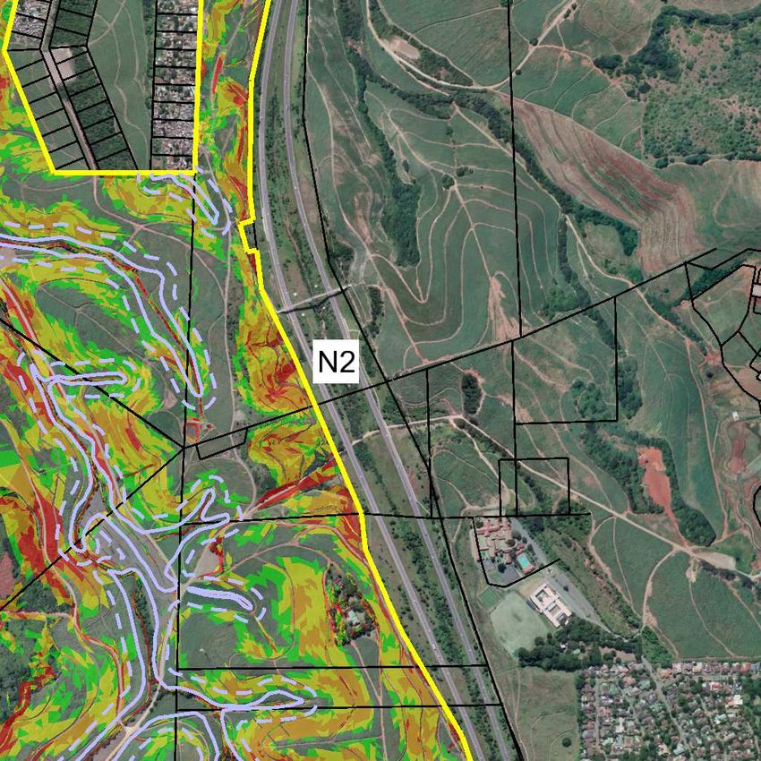
TONGAAT HULETT DEVELOPMENTS
CORNUBIA PHASE 2
Engineering Services Report

NOTE

Certain information gleaned from the following sources has been used in the compilation
of this report –

•      Bulk Services Planning Report for future developments in the Northern Region, Report
       No. DR2014/07 compiled by SMEC in April 2014.
•      Cornubia Phase 1 Engineering Services Report Revision 3, Report No. 2009/17
       compiled by SMEC in February 2011.
•      Tongaat Hulett Development – Cornubia Phase 2 Traffic Impact Assessment,
       Document No. 122391 compiled by Hatch Goba in January 2014.
•      Stormwater Management Plan – Cornubia Phase 2, Report No. DR2013/19 compiled
       by SMEC in July 2013.
•      Investigations of the sewer options proposed to cater for the Retail Park Development
       with the Cornubia Precinct, Report No. DR2014/29 compiled by SMEC in June 2014
•      Proposed Bulk Water and Sewer Infrastructure Planning Report Revision 1, Report
       No. DR2010/12 compiled by SMEC in June 2012.
•      Cornubia Phase 1B Water Modelling Report, Report No. DR2014/39 compiled by
       SMEC in June 2014.
•      Blackburn Reservoir Modelling Report Revision 3, Project No. D294, compiled by
       Naidu Consulting in January 2013.
•      Attenuation Facilities Within Wetlands Analysis Report – Cornubia Phase 2, Report
       No. DR2014/70 compiled by SMEC in October 2014.
•      Framework Roads Alignment Changes –Cornubia Phase 2, Report No. DR 2013/45
       compiled by SMEC in October 2013.
•      Concept Design Report: Cornubia Urban Irrigation. Report No DR2015/03, compiled
       by SMEC in February 2015.
•      Investigation of the Sewer Options Proposed to Cater for the ‘Retail Park’
       Development within the Cornubia Precinct, Report no. DR2014-29

V:\DH0003_CORNUPH2\1_Project Management\1-5_Latest Reports\Cornubia Phase 2 Engineering Service Report\REVISION 2\Cornubia Engineering Services Report-PH2-Rev 2.docx   Page | ii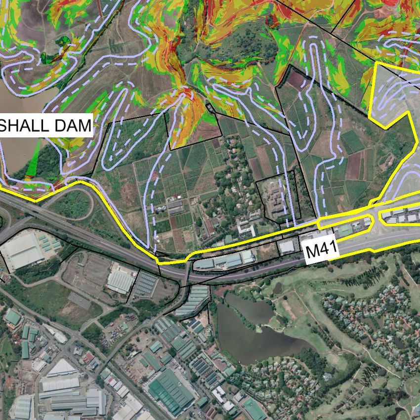
TONGAAT HULETT DEVELOPMENTS
CORNUBIA PHASE 2
Engineering Services Report

                                                          TABLE OF CONTENTS

1. INTRODUCTION ............................................................................................... 1
        1.1 Background ......................................................................................................... 1
        1.2 Location and Extent ............................................................................................. 1
        1.3 Description of Site ............................................................................................... 2
        1.4 Topography ......................................................................................................... 2

2. TERMS OF REFERENCE ................................................................................. 2
3. LAND USES ..................................................................................................... 3
4. BULK INFRASTRUCTURE .............................................................................. 4
        4.1 Water 4
           4.1.1 Proposed Water Demand ........................................................................... 4
              4.1.2          Proposed Ultimate Bulk Water Infrastructure.............................................. 4
              4.1.3          Proposed Blackburn Reservoir ................................................................... 4
              4.1.4          Conclusion ................................................................................................. 5
        4.2 Sewer .................................................................................................................. 6
           4.2.1 Existing Bulk Sewer Infrastructure.............................................................. 6
              4.2.2          Waste Water Treatment Works (WWTW)................................................... 6
              4.2.3          Sewer Catchments ..................................................................................... 7
              4.2.4          Conclusion ................................................................................................. 8
        4.3 Roads .................................................................................................................. 9
           4.3.1 Roads Hierarchy ........................................................................................ 9
              4.3.2          Road Classification .................................................................................... 9
              4.3.3          Class 3 Roads............................................................................................ 9
              4.3.4          Ultimate Access Points ............................................................................ 10
              4.3.5          Pedestrians .............................................................................................. 10
              4.3.6          Traffic Impact Assessment ....................................................................... 10
              4.3.7          Public Transport Network ......................................................................... 11
              4.3.8          Conclusion ............................................................................................... 11

5. STORMWATER .............................................................................................. 12
        5.1 Stormwater Management Plan .......................................................................... 12
        5.2 Stormwater Attenuation Facilities....................................................................... 12
V:\DH0003_CORNUPH2\1_Project Management\1-5_Latest Reports\Cornubia Phase 2 Engineering Service Report\REVISION 2\Cornubia Engineering Services Report-PH2-Rev 2.docx   Page | iii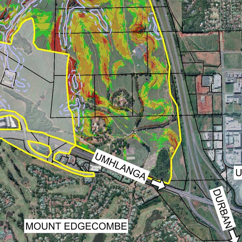
TONGAAT HULETT DEVELOPMENTS
CORNUBIA PHASE 2
Engineering Services Report

6. WETLAND CROSSINGS ................................................................................ 13
        6.1 Design Philosophy ............................................................................................. 13

7. BULK IRRIGATION ........................................................................................ 14
8. TOPOGRAPHICAL SURVEY ......................................................................... 14
9. INTERNAL SERVICES ................................................................................... 15
        9.1 Water 15
        9.2 Sewer ................................................................................................................ 15
        9.3 Roads ................................................................................................................ 15
        9.4 Stormwater ........................................................................................................ 15

10. ADDITIONAL INFORMATION ........................................................................ 15
11. LIST OF DRAWINGS...................................................................................... 16
12. LIST OF TABLES ........................................................................................... 17
13. ANNEXURES ........................................ ERROR! BOOKMARK NOT DEFINED.

FIGURE INDEX

Figure 1: Extent of Cornubia Phase 2 ................................................................................ 1
Figure 2: Description of Relevant Land Uses..................................................................... 3
Figure 3: Phase 2 - Description of Site................................................................... Drawings
Figure 4: Phase 2 - Slope Analysis........................................................................ Drawings
Figure 5: Phase 2 – Lum Precinct Plan.................................................................. Drawings
Figure 6: Phase 2 - Bulk Water.............................................................................. Drawings
Figure 7: Phase 2 – Bulk Sewer............................................................................. Drawings
Figure 8: Phase 2–Proposed Sewer Catchments.................................................. Drawings
Figure 9: Phase 2–Proposed Sewer Links............................................................. Drawings
Figure 10: Phase 2-Framework Roads.................................................................. Drawings
Figure 11: Proposed Blackburn Interchange Layout.............................................. Drawings
Figure 12: Proposed Cornubia Bridge Layout....................................................... Drawings
Figure 13: Proposed M41/Flanders Drive Interchange Layout............................. Drawings
Figure 14: Proposed M41/Marshall Dam Interchange Layout............................... Drawings
Figure 15: Proposed R102/Northern Drive Interchange Layout............................ Drawings
Figure 16: Phase 2-Wetland Crossings................................................................. Drawings
Figure 17: Proposed Bulk Irrigation....................................................................... Drawings
Figure 18: Phase 2 – Proposed Zones.................................................................. Drawings

V:\DH0003_CORNUPH2\1_Project Management\1-5_Latest Reports\Cornubia Phase 2 Engineering Service Report\REVISION 2\Cornubia Engineering Services Report-PH2-Rev 2.docx   Page | iv
TONGAAT HULETT DEVELOPMENTS
CORNUBIA PHASE 2
Engineering Services Report

TABLE INDEX

Table 1: Cornubia Phase 2 Lums Precinct Plan Area Schedule.................................Tables
Table 2: Water Demand Generation...........................................................................Tables
Table 3 Water Storage Required For Phase 2............................................................Tables
Table 4: Contributions to Blackburn Reservoir Starter Cell.........................................Tables
Table 5: Storage Required For Blackburn Contributions.............................................Tables
Table 6: Sewer Flow Generation.................................................................................Tables

ANNEXURES

Correspondence for Sewer.................................................................................. Annexures

V:\DH0003_CORNUPH2\1_Project Management\1-5_Latest Reports\Cornubia Phase 2 Engineering Service Report\REVISION 2\Cornubia Engineering Services Report-PH2-Rev 2.docx   Page | v
TONGAAT HULETT DEVELOPMENTS
CORNUBIA PHASE 2
Engineering Services Report

1.               INTRODUCTION
1.1              Background
                 The Cornubia Precinct has been planned as a Mixed Use Phased Development
                 and includes a “Breaking New Ground Housing Initiative” by Tongaat Hulett
                 Developments (Pty) Ltd in association with eThekwini Municipality. The purpose
                 of this report is to identify the availability of existing bulk infrastructure for
                 Phase 2, and to assess the requirements for additional bulk services.

1.2              Location and Extent
                 The entire Cornubia Precinct encompasses an area of approximately 1300ha,
                 bounded in the East by the N2, generally in the South by the M41 and Flanders
                 Drive and generally in the north by the Ohlanga River.
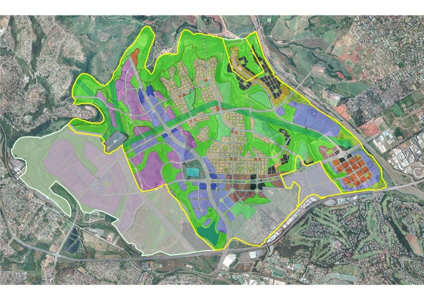
                 Phase 2 of the development encompasses an area of approximately 907ha and
                 is bounded in the east by the N2 highway, the R102 in the south, the Ohlanga
                 River in the north and Cornubia Phase 1 in the west.

                                                           Figure 1: Extent of Cornubia Phase 2

V:\DH0003_CORNUPH2\1_Project Management\1-5_Latest Reports\Cornubia Phase 2 Engineering Service Report\REVISION 2\Cornubia Engineering Services Report-PH2-Rev 2.docx   Page | 1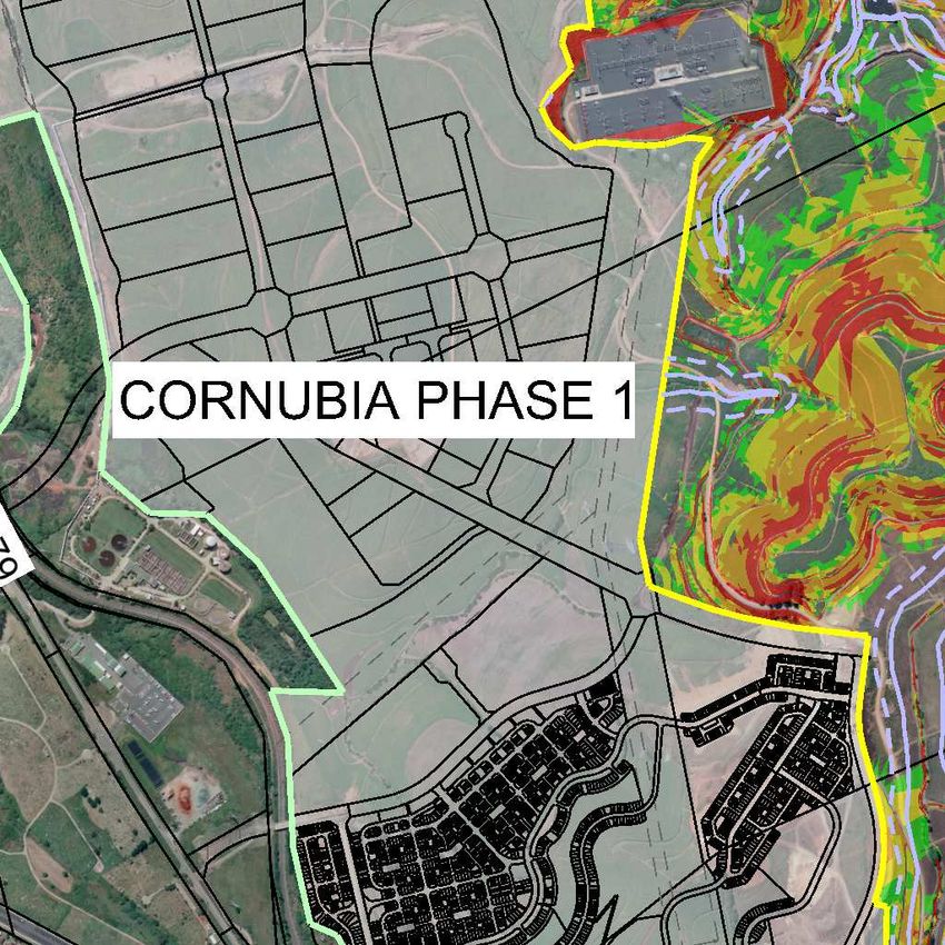
TONGAAT HULETT DEVELOPMENTS
CORNUBIA PHASE 2
Engineering Services Report

1.3              Description of Site
                 Reference needs to be made to FIGURE 3.
                 Currently major portions of the site are under sugar cane cultivation which
                 requires the existing myriad network of gravel haul roads which generally follow
                 the contours.
                 There are several notable features on the site as follows –
                 •      South African Sugar Association (SASA) Headquarters and Experimental
                        Station some 60ha in extent.
                 •      Marshall Dam
                 •      Ottawa Major Substation
                 •      Pockets of natural forest some 31ha in extent
                 •      Electrical Switching Station
                 •      35,0m wide electrical servitude from the existing switching station in the south
                        east of the site running north and then west towards the Ottawa Substation
                 •      5,0m wide sewer servitude running from the north east corner of the site in a
                        westerly direction towards the Waterloo pump station
                 •      An existing 600mm diameter raw water supply pipeline which is not in a
                        servitude
                 •      NAA Water pipeline in 12m servitude

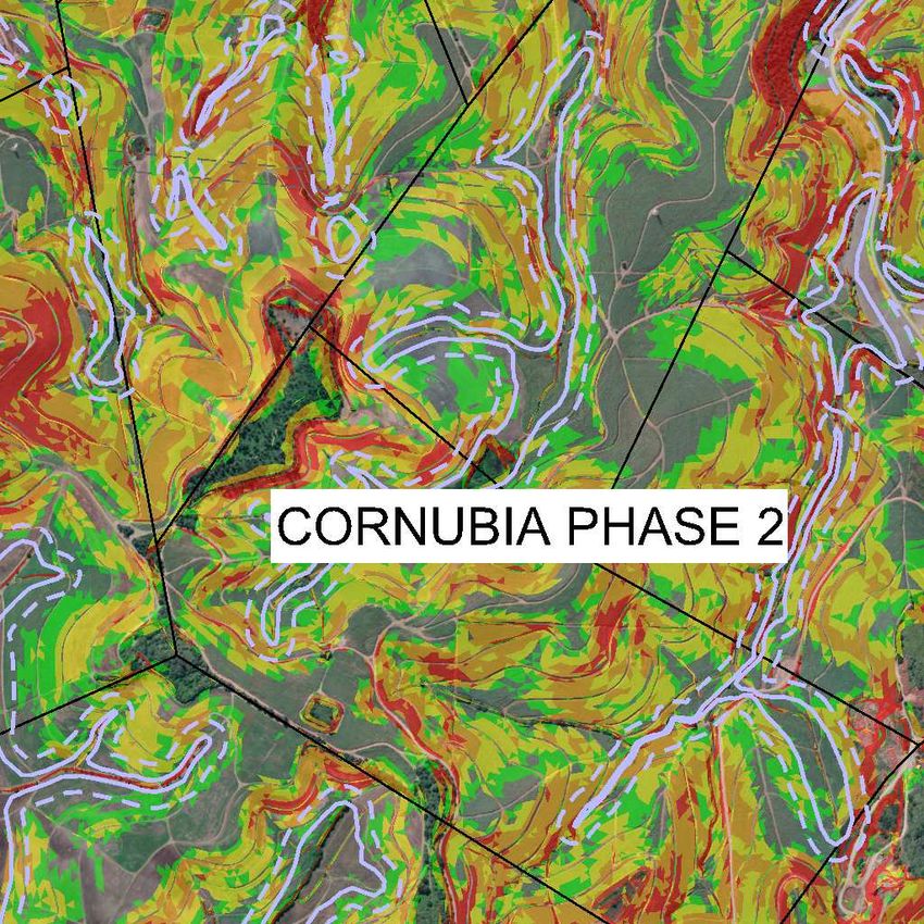
1.4              Topography
                 Reference needs to be made to FIGURE 4.
                 FIGURE 4 shows the slope analysis of the Phase 2 area. As can be seen from
                 the legend on the drawing more than 50% (458ha) of the area is flatter than
                 1 in 6.

2.               TERMS OF REFERENCE
                 SMEC has been part of the project planning team for this development since
                 2005. In May 2014, SMEC was requested by Tongaat Hulett Developments
                 (THD) to prepare this Engineering Services Report for Phase 2 of the
                 Development.

V:\DH0003_CORNUPH2\1_Project Management\1-5_Latest Reports\Cornubia Phase 2 Engineering Service Report\REVISION 2\Cornubia Engineering Services Report-PH2-Rev 2.docx   Page | 2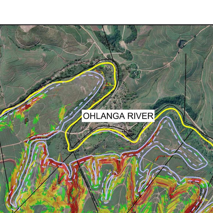
TONGAAT HULETT DEVELOPMENTS
 CORNUBIA PHASE 2
 Engineering Services Report

 3.               LAND USES
                  Reference needs to be made to FIGURE 5 and TABLE 1.
                  A land use layout plan for the Cornubia Precinct was prepared by Iyer Urban
                  Design Studio including two typologies for Cornubia Boulevard as indicated on
                  the Figure 5 inset (Typology subject to eThekwini approval and endorsement).
                  The mix of the various land uses as well as the projected yield of housing units
                  (approximately 22 134) for the Phase 2 development is shown on TABLE 1 -
                  Cornubia Phase 2 LUMS Precinct Plan and Area Schedule.
                  Refer to FIGURE 2 below for a brief explanation of the relevant land uses: -

Figure 2: Description of Relevant Land Uses

                           LAND USES                                                                                  DESCRIPTION
         Medium Density Residential - Subsidised                                     Anticipated 3 storey apartments with a projected 80 units
         Duplex / Simplex Housing (BNG)                                              per hectare and unit sizes of 50sqm.
                                                                                     Anticipated 3 storey apartments with a projected 218
         Medium Density Residential - Affordable
                                                                                     units per hectare and unit sizes of 55sqm.
                                                                                     Anticipated 4 storey apartments with a projected 291
         High Density Residential - Affordable
                                                                                     units per hectare and unit sizes of 55sqm.
                                                                                     Anticipated 4 storeys with a 90%/10% split between
         Mixed Use 1 (Residential Apartments +
                                                                                     residential and Retail. Residential density to be 262 units
         Retail Base) - 90% / 10% desired split)
                                                                                     per hectare with unit sizes of 55sqm.
                                                                                     Anticipated 6 storeys with a 90%/10% split between
         Mixed Use 2 (Residential Apartments +
                                                                                     residential and Retail. Residential density to be 360 units
         Retail Base) - 90% / 10% desired split)
                                                                                     per hectare with unit sizes of 60sqm.
                                                                                     Anticipated 12 storeys minimum with a 90%/10% split
         T.O.D 1 zone Mixed Use (With Residential)
                                                                                     between residential and commercial. Residential density
         (90% / 10% desired split)
                                                                                     to be 600 units per hectare with unit sizes of 60sqm.
         T.O.D 2 zone Commercial Only (No
                                                                                     Anticipated 8 storeys minimum with a FAR of 3.0.
         Residential)
                                                                                     This zone would include opportunities for retail activities
         General Business
                                                                                     such as business parks, offices, showrooms, retail etc.
                                                                                     This zone could contain a mixture of logistics,
         Light Industry                                                              warehousing, light industry as well as opportunities for
                                                                                     larger scale retail park activity.
                                                                                     This would include schools, clinics, government offices,
         Social Facilities                                                           multi-purpose halls, sports fields, swimming pool, police
                                                                                     station, libraries and fire station.
                                                                                     This would include allowing for hospitals, schools, health
         Community Facility                                                          centre, children’s home, cemetery, old age home and
                                                                                     early childhood centre.
                                                                                     Open Space areas encompassing wetlands, buffers and
         Open Space
                                                                                     forests.
                                                                                     This is the area set aside for the Proposed 80Ml Blackburn
         Blackburn Reservoir                                                         Reservoir dedicated to supply water to the Cornubia
                                                                                     Precinct.
                                                                                     This includes the total area of all the planned road
         Roads
                                                                                     reserves.

 V:\DH0003_CORNUPH2\1_Project Management\1-5_Latest Reports\Cornubia Phase 2 Engineering Service Report\REVISION 2\Cornubia Engineering Services Report-PH2-Rev 2.docx   Page | 3
TONGAAT HULETT DEVELOPMENTS
CORNUBIA PHASE 2
Engineering Services Report
4. BULK INFRASTRUCTURE
4.1 Water
4.1.1 Proposed Water Demand
Reference needs to be made to TABLE 2 and TABLE 3.
TABLE 2 indicates a total Average Daily Demand ADD for Phase 2 of
approximately 30.12 Ml/day. TABLE 3 indicates a required reservoir storage
capacity of approximately 61 Ml and this includes allowance for 3.56 Ml fire flow
in the additional 24 hour storage capacity.
4.1.2 Proposed Ultimate Bulk Water Infrastructure
Reference needs to be made to FIGURE 6.
Currently there is no existing water infrastructure to serve Phase 2. The ultimate
water supply for the entire Cornubia Development will be provided by the
proposed Blackburn Reservoir, refer to the Bulk Services Planning Report for
future developments in the Northern Region Report No. DR2014/07 compiled by
SMEC.
The supply to the Blackburn Reservoir will be provided by the Northern Aqueduct.
According to the Blackburn Reservoir Modelling Report Rev 2, Project No.
D294/01 prepared by Naidu Consulting, the first phase of the Northern Aqueduct
augmentation will increase capacity of the system to supply water from Durban
Heights to Phoenix 2, Blackburn, Waterloo and Umhlanga 2 Reservoirs. This
augmentation will result in additional capacity of 44 Ml/day into the current
system. This is due for completion by 2016.
Ultimately in the second phase, the Northern Aqueduct will be supplied by the
Western Aqueduct once it is completed. According to the Bulk Services Planning
Report for future developments in the Northern Region Report No. DR2014/07
compiled by SMEC, this is scheduled for completion towards the end of 2021.
4.1.3 Proposed Blackburn Reservoir
Reference needs to be made to TABLE 4 and TABLE 5.
The proposed Blackburn Reservoir will be constructed in phases in order to meet
future demands. The first phase of construction will commence in 2015.
This initial reservoir storage needs to cater for the existing Phase 1 which
includes Phase 1A Housing, 1B Housing (currently supplied by Phoenix 2
Reservoir) and the Retail Park. According to the Blackburn Reservoir Modelling
Report Project No D294 compiled by Naidu Consulting, there is also a portion of
Mount Edgecombe/Phoenix demand that will be transferred from the Phoenix 1
Reservoir zone to the Blackburn Reservoir zone in order to free up storage
capacity at Phoenix 1 Reservoir. This demand also needs to be catered for in the
initial storage.
V:\DH0003_CORNUPH2\1_Project Management\1-5_Latest Reports\Cornubia Phase 2 Engineering Service Report\REVISION 2\Cornubia Engineering Services Report-PH2-Rev 2.docx Page | 4TONGAAT HULETT DEVELOPMENTS
CORNUBIA PHASE 2
Engineering Services Report
From Table 4 and 5, the initial reservoir storage required is approximately 25 Ml
This includes an allowance of 1.45 Ml for fire flow in the additional 24 hour
storage capacity.
4.1.4 Conclusion
• The total water ADD estimated for Phase 2 is 30.12 Ml/day and a storage of
61 Ml is required
• Phase 2 water supply will be sourced from the new Blackburn Reservoir.
• The Blackburn Reservoir will initially be supplied by the augmented Northern
Aqueduct which is currently under construction and due for completion in
2016. The augmentation will supply an additional 44 Ml /day into the current
system.
• Ultimately the Northern Aqueduct will be supplied by the Western Aqueduct
which is scheduled to be completed by the end of 2021.
• Blackburn Reservoir will be constructed in phases. The first phase of
construction will commence in 2015 and an initial storage of approximately 25
Ml is required. In the event that a smaller reservoir is constructed under the
first phase of the reservoir construction, indications form EWS has been that
the storage capacity could be reduced to the early 30 hour range in the short
term to facilitate development needs.
• Suitable bulk water infrastructure will be available to ensure adequate
capacity to meet the water demands for any future developments within
Phase 2.
V:\DH0003_CORNUPH2\1_Project Management\1-5_Latest Reports\Cornubia Phase 2 Engineering Service Report\REVISION 2\Cornubia Engineering Services Report-PH2-Rev 2.docx Page | 5TONGAAT HULETT DEVELOPMENTS
CORNUBIA PHASE 2
Engineering Services Report
4.2 Sewer
4.2.1 Existing Bulk Sewer Infrastructure
Reference needs to be made to FIGURE 7.
The whole of Cornubia is divided by a main ridgeline running west to east. The
northern catchments gravitate to the Phoenix Waste Water Treatment Works
(WWTW). The southern catchment gravitates to the Kwa-Mashu WWTW.
Aurecon has recently completed the upgrade of the Ohlanga Pump Station, the
new rising main and the Ohlanga gravity trunk sewer. This gravity trunk sewer
runs east to west across Cornubia and discharges directly into the Phoenix
WWTW. This gravity trunk sewer will deal adequately with the overall sewer from
the northern catchments.
Sewer from the southern catchment will discharge into the Eastbury Trunk Sewer
which gravitates to the Kwa-Mashu WWTW.
4.2.2 Waste Water Treatment Works (WWTW)
The following information regarding the Phoenix and Kwa-Mashu WWTW has
been confirmed by Ms Precious Mbhele of eThekwini Water and Sanitation EWS,
Refer to Appendix C1.
• Phoenix WWTW
Operating (design) capacity - 25 Ml/day
Current yearly average operating load - 18 Ml/day
Spare capacity - 0 Ml/day
Sludge handling capacity has restricted the works to 18 Ml/day as opposed to
25 Ml/day. EWS have stated that currently they are increasing sludge dewatering
and digestion facilities to meet the 7 Ml/day shortfall. This is anticipated to be
completed by mid-2015.
EWS is also planning to upgrade the works on the current site to a capacity of
50 Ml/day. This is anticipated to be completed by 2016.
Ultimately EWS plans to upgrade the works to a capacity of 100 Ml/day.
V:\DH0003_CORNUPH2\1_Project Management\1-5_Latest Reports\Cornubia Phase 2 Engineering Service Report\REVISION 2\Cornubia Engineering Services Report-PH2-Rev 2.docx Page | 6TONGAAT HULETT DEVELOPMENTS
CORNUBIA PHASE 2
Engineering Services Report
• Kwa-Mashu WWTW
Operating (design) capacity - 65 Ml/day
Current yearly average operating load - 60 Ml/day
Spare capacity - 5 Ml/day
EWS has proposed an upgrade to a capacity of 75 Ml/day which is due for
completion by 2015.
It should be noted that the additional capacities will be utilized as and when
developments arise within the Ohlanga and Umgeni River Catchments and is not
specifically set aside for the Cornubia Development.
4.2.3 Sewer Catchments
Reference needs to be made to FIGURE 8 and TABLE 6.
The total sewer Average Daily Flow (ADF) for Phase 2 is approximately
30.05 Ml/day. The topography of the site is such that the watershed lines
determine that the sewer effluent needs to be dealt with in five different sub-
catchment areas as shown on FIGURE 8.
Reference also needs to be made to the report prepared by SMEC, Investigation
of the Sewer Options Proposed to Cater for the ‘Retail Park’ Development within
the Cornubia Precinct, Report no. DR2014-29. This covers the Cornubia Retail
Park which is not included in these calculations, but sewer gravity main sizing
has taken cognisance of the full development yields and flows.
• Northern Catchments
Reference needs to be made to FIGURE 9.
Sewer generated from sub-catchments 1A, 3, 4 and 5 will gravitate to the new
Ohlanga gravity trunk sewer and be treated at the Phoenix WWTW. Sewer
effluent from sub-catchments 1B and 2 will gravitate to the Ohlanga sewer pump
station and be pumped to the Phoenix WWTW. The total sewer ADF to be
treated at Phoenix WWTW is approximately 27.18 Ml/day.
• Southern Catchment
Reference needs to be made to FIGURE 9.
Sewer generated from sub-catchment 6 of approximately 2.87 Ml/day, will
gravitate to the Eastbury gravity trunk sewer to be treated at the Kwa-Mashu
WWTW.
V:\DH0003_CORNUPH2\1_Project Management\1-5_Latest Reports\Cornubia Phase 2 Engineering Service Report\REVISION 2\Cornubia Engineering Services Report-PH2-Rev 2.docx Page | 7TONGAAT HULETT DEVELOPMENTS
CORNUBIA PHASE 2
Engineering Services Report
4.2.4 Conclusion
• The total sewer ADF estimated for Phase 2 is 30.05 Ml/day.
• Sewer will be dealt with in 7 sub-catchments. The sewer ADF from catchment
1A – 5 of 27.18 Ml/day will be treated at the Phoenix WWTW. Sewer ADF
from catchment 6 of 2.87 Ml/day will gravitate to the Eastbury gravity trunk
sewer to be treated at the Kwa-Mashu WWTW.
• The Kwa-Mashu WWTW currently has a spare capacity of 5 Ml/day however
a proposed upgrade to a capacity of 75 Ml/day is planned and will be
completed by 2015.
• The Phoenix WWTW is currently at capacity. EWS are busy increasing the
sludge handling facilities on site to free up 7 Ml/day which will be completed
by mid-2015. The works will be upgraded to a capacity of 50 Ml/day which is
anticipated to be completed by 2016.
• EWS ultimately plans to upgrade the Phoenix WWTW to a capacity of
100 Ml/day.
• Bulk sewer infrastructure planning is being implemented to ensure adequate
capacity is available ahead of time for any future developments within
Phase 2.
V:\DH0003_CORNUPH2\1_Project Management\1-5_Latest Reports\Cornubia Phase 2 Engineering Service Report\REVISION 2\Cornubia Engineering Services Report-PH2-Rev 2.docx Page | 8TONGAAT HULETT DEVELOPMENTS
CORNUBIA PHASE 2
Engineering Services Report
4.3 Roads
4.3.1 Roads Hierarchy
The road hierarchy model adopted for the overall development of Cornubia
generally follows the standard design guidelines normally applied to a project of
this magnitude.
4.3.2 Road Classification
The road classification with related traffic calming measures is as follows –
• Class 1: Freeway – High mobility, no or very limited at grade access. No
traffic calming
• Class 2: Major Arterial/ Regional Distributor – High mobility, limited at grade
access (intersections), no direct property access. No traffic calming.
• Class 3: Arterial/ Major Collector – Balanced mobility and accessibility
function. Traffic calming only to consist of signage and road markings.
• Class 4: Collector – More accessibility, less mobility, direct property access.
All types of traffic calming allowed.
• Class 5: Local Street – Limited mobility, more accessibility. All types of traffic
calming allowed including speed humps.
4.3.3 Class 3 Roads
Reference needs to be made to FIGURE 10 and Report No. DR 2013/45 -
Framework Roads Alignment Changes –Cornubia Phase 2 compiled by SMEC in
October 2013.
The following class 3 roads will need to be constructed in Phase 2: -
• Extension of Cornubia Boulevard from Cornubia Industrial and Business
Estate (CIBE). Cornubia Boulevard traverses the Southern portion of
Cornubia and runs parallel to the R102/M41. Cornubia Boulevard links
directly in the east into Umhlanga Ridge Boulevard. Limited access onto
Cornubia Boulevard from the N2 via a north bound off ramp is provided as
part of the Mount Edgecombe Interchange upgrade. Cornubia Boulevard is
also the road that houses the IRPTN in future. Through engagement with
ETA and ethekwini Road provision the Horizontal and Vertical alignment of
this road has been agreed. Reference needs to be made to the Town
planning report and the TIA for finalisation on the TRL and configurations
proposed.
• The extension of Blackburn Link from CIBE/Ottawa Substation intersection.
Blackburn Link traverses the northern portion of Cornubia and links up to the
N2 in the east.
V:\DH0003_CORNUPH2\1_Project Management\1-5_Latest Reports\Cornubia Phase 2 Engineering Service Report\REVISION 2\Cornubia Engineering Services Report-PH2-Rev 2.docx Page | 9TONGAAT HULETT DEVELOPMENTS
CORNUBIA PHASE 2
Engineering Services Report
• Dube West is a natural extension of Phoenix Highway. The existing Marshall
Dam interchange and intersection of the M41 Phoenix Highway will require
major reconfiguration to allow for the connection of Dube West. Dube West
runs midway through Cornubia and it is the intention that this will ultimately
link up to the west of the Dube Tradeport. In the short term Dube West ends
north of the Ohlanga River.
• Dube East originates from Flanders Drive in the south. It runs parallel to the
N2 freeway and is midway between Dube West and the N2 freeway. Dube
East is also intended to be extended northwards to the east of Dube
Tradeport. In the short term it will terminate at the Ohlanga River in the north
4.3.4 Ultimate Access Points
Reference needs to be made to FIGURES 10 to 15.
Seven ultimate Access points have been proposed for as follows-
1. Proposed Blackburn Interchange on the N2.
2. Proposed bridge over the N2 linking Cornubia Boulevard and Umhlanga
Ridge Boulevard in URTC currently out to tender.
3. Proposed M41/Flanders Drive Interchange (upgrade).
4. Proposed M41/Marshall Dam Interchange (upgrade).
5. Proposed Northern Drive Interchange.
6. Proposed bridge over the Ohlanga River from Dube West linking up to
Waterloo road network and future developments to the north of Cornubia.
7. Proposed bridge over the Ohlanga River from Dube East linking up to future
developments to the north east of Cornubia.
4.3.5 Pedestrians
According to the Cornubia Phase 1 Engineering Services Report No.DR2009/17,
adequate provision will be made to ensure that sufficient width is allowed for
within the sidewalks to accommodate pedestrians.
4.3.6 Traffic Impact Assessment
The traffic volumes generated by the abovementioned network of roads,
intersection and lane requirements is addressed in a separate report entitled
Tongaat Hulett Developments - Cornubia Phase 2 Traffic Impact Assessment
TIA, Document No. 122391, prepared by Hatch Goba.
V:\DH0003_CORNUPH2\1_Project Management\1-5_Latest Reports\Cornubia Phase 2 Engineering Service Report\REVISION 2\Cornubia Engineering Services Report-PH2-Rev 2.docx Page | 10TONGAAT HULETT DEVELOPMENTS
CORNUBIA PHASE 2
Engineering Services Report
4.3.7 Public Transport Network
According to the TIA stated in the clause above, the following public transport
services will be incorporated:
• Bus Rapid Transit (BRT) Services
Two main BRT services will be provided within Cornubia, namely King Shaka
International Airport to Durban CBD via Umhlanga (C8 corridor) and Bridge City
to Umhlanga Ridge New Town Centre (C9 corridor).
• Feeder Services
Feeder Services will provide local bus services that will support the BRT routes.
This will improve the access to the BRT service and local road networks
• Quality Bus Services (QBS)
The QBS will transport passengers not within the catchment areas of the BRT
routes. The QBS routes will be located outside of Cornubia.
4.3.8 Conclusion
• In Phase 2 the following class 3 roads will be need to be constructed – Dube
West, Dube East, a portion of Cornubia Boulevard and a portion of Blackburn
Link.
• A separate TIA analysing traffic volumes and discussing the Public Transport
Network has been prepared by Hatch Goba.
• There will ultimately be 7 access points into Cornubia.
• All proposed roads and interchanges will be constructed in a phased manner
to meet the required demands over time.
V:\DH0003_CORNUPH2\1_Project Management\1-5_Latest Reports\Cornubia Phase 2 Engineering Service Report\REVISION 2\Cornubia Engineering Services Report-PH2-Rev 2.docx Page | 11TONGAAT HULETT DEVELOPMENTS
CORNUBIA PHASE 2
Engineering Services Report
5. STORMWATER
5.1 Stormwater Management Plan
A Stormwater Management Plan was prepared by SMEC in July 2013. Adequate
stormwater control measures are proposed and will be implemented in line with
Ethekwini Municipality’s requirements. Refer Report No DR2013/19, Stormwater
Management Plan – Cornubia Phase 2.
5.2 Stormwater Attenuation Facilities
A Stormwater Attenuation Facility report was prepared by SMEC in November
2014 analysing the feasibility of attenuation features outside the wetland
boundaries. Refer to Report No DR2014/70, Attenuation Facilities Within
Wetlands Analysis Report – Cornubia Phase 2. The aim of the report is to explain
the engineering and cost benefits of attenuating within the wetlands.
V:\DH0003_CORNUPH2\1_Project Management\1-5_Latest Reports\Cornubia Phase 2 Engineering Service Report\REVISION 2\Cornubia Engineering Services Report-PH2-Rev 2.docx Page | 12TONGAAT HULETT DEVELOPMENTS
CORNUBIA PHASE 2
Engineering Services Report
6. WETLAND CROSSINGS
6.1 Design Philosophy
Reference needs to be made to FIGURE 16.
The following basic design philosophy for wetland crossings will apply during the
course of the development of Phase 2:
• All new major access roads crossing wetlands will be supported by bridge
structures where feasible. Care will be taken to avoid sensitive forest and
wetland areas (where practical) when locating intermediate bridge supports.
• Where impractical to construct a bridge over wetlands and minor roads, the
roads will be constructed on a layer of clean dump rock of sufficient depth to
allow movement of groundwater under the road embankment in the valley
bottom/wetland.
• Pipe crossings (typically water and sewer) and other services such as Telkom
and electrical cables shall be ducted and designed within or attached to
bridge structures where planning permits.
• Pipe crossings (particularly gravity services), over steep narrow wetland
valley lines (where no structure is planned), will be designed as pipe bridges
with pier locations designed to avoid or minimise impact on sensitive forest
and wetland areas.
• Pipe crossings over flat wide valley lines should be designed to coincide with
the necessary control devices i.e. where a storm water attenuation structure
in a valley line is required to prevent erosion, the service crossing should be
designed as an integral component of the device.
• Where no other alternative exists, pipes will need to be buried and alignment
must avoid sensitive vegetation.
• Where practical all services (longitudinally) will be located outside of
sensitive/wetland areas, else within buffers.
V:\DH0003_CORNUPH2\1_Project Management\1-5_Latest Reports\Cornubia Phase 2 Engineering Service Report\REVISION 2\Cornubia Engineering Services Report-PH2-Rev 2.docx Page | 13TONGAAT HULETT DEVELOPMENTS
CORNUBIA PHASE 2
Engineering Services Report
7. BULK IRRIGATION
Reference needs to be made to FIGURE 17 and 18.
A Master Irrigation Plan was prepared by SMEC in February 2015. The purpose
of this report is to advise towards an efficient bulk irrigation system comprising a
source, storage nodes and reticulation to best serve the planned urban
landscape of roads and open spaces within Cornubia’s Phase 1 and 2
developments. Refer Report No DR2015/03, Concept Design Report: Cornubia
Urban Irrigation.
8. TOPOGRAPHICAL SURVEY
A comprehensive topographical survey of the entire Cornubia Precinct was
carried out by R.A Logan & Associates during the period early 2006 to early 2008
for Tongaat Hulett Developments. The survey complied with the relevant project
specifications and TMH 11: Standard Survey Methods (1997).
• Permanent Survey Stations which may be used for setting out of construction
work. (Installed by Wall Marriott Paul & Borgen)
• Electronic Data
“All topographical details, inclusive of contours have been captured digitally
on different layers/ levels. Final CAD and DTM have been provided”.
• “Digital Terrain Model” (DTM) Tolerances
Point density is sufficient to meet the listed DTM tolerances when a linear
interpolation made between two successive feature points. Sufficient spot
heights have been taken to provide accuracy of contours to 0,5m vertical
intervals at a scale of 1:500.
All the digital information is held at SMEC’s offices and is available for use by all
parties who require the information for the design of the various construction
elements. There is always the possibility that further detailed survey may be
required to enable new services to tie into existing services i.e. sewers, water
mains and roads.
V:\DH0003_CORNUPH2\1_Project Management\1-5_Latest Reports\Cornubia Phase 2 Engineering Service Report\REVISION 2\Cornubia Engineering Services Report-PH2-Rev 2.docx Page | 14TONGAAT HULETT DEVELOPMENTS
CORNUBIA PHASE 2
Engineering Services Report
9. INTERNAL SERVICES
9.1 Water
All internal water reticulation will be designed by and in accordance with
eThekwini Water Section’s standards and subject to their approvals.
9.2 Sewer
All internal sewer reticulation will be designed in accordance with eThekwini
Wastewater Section’s standards and subject to their approvals.
9.3 Roads
All internal roads will be designed in accordance and conjunction with the
eThekwini road design manual – Part 3 (1985) with occasional reference to the
relevant UTG standards, all designs will be subject to approval from: eThekwini
Roads/ Materials Department, eThekwini Transport Authority and eThekwini
Roads Provision.
9.4 Stormwater
All internal stormwater reticulation will be designed in accordance with the layout
and sizes of the various stormwater elements as determined by the Stormwater
Management Plan and the relevant applicable standards. The design will be
subject to the approval of eThekwini Coastal and Drainage Section.
10. ADDITIONAL INFORMATION
During the detailed design stage of each individual phase of the development it
will be necessary to confirm the following aspects –
• Sizes, positions and levels of existing underground services i.e. water mains,
sewers and storm water pipes.
• Levels of existing roads at new tie-in positions.
• Additional topographical survey.
V:\DH0003_CORNUPH2\1_Project Management\1-5_Latest Reports\Cornubia Phase 2 Engineering Service Report\REVISION 2\Cornubia Engineering Services Report-PH2-Rev 2.docx Page | 15TONGAAT HULETT DEVELOPMENTS
CORNUBIA PHASE 2
Engineering Services Report
11. LIST OF DRAWINGS
FIG DRAWING No. DESCRIPTION
CORNUBIA PRECINCT - PHASE 2 - DESCRIPTION OF
3 DH0003-PHASE 2-GEN-01 SHT 1
SITE
4 DH0003-PHASE 2-SLOPES-01 SHT 1 CORNUBIA PRECINCT - PHASE 2 - SLOPE ANALYSIS
5 CORN-BLOCK EIA-12498-16 CORNUBIA PHASE 2 – LUM PRECINCT PLAN
6 DH0003-PHASE 2-WATER-01 SHT 1 CORNUBIA PRECINCT - PHASE 2 – BULK WATER
7 DH0003-PHASE 2-SEWER-01 SHT 1 CORNUBIA PRECINCT - PHASE 2 – BULK SEWER
CORNUBIA PRECINCT - PHASE 2 – PROPOSED SEWER
8 DH0003-PHASE 2-SEWER-01 SHT 2
CATCHMENTS
CORNUBIA PRECINCT - PHASE 2 – PROPOSED SEWER
9 DH0003-PHASE 2-SEWER-01 SHT 3
LINKS
DH0003-PHASE 2-FRAMEWORK
10 CORNUBIA PRECINCT-PHASE 2-FRAMEWORK ROADS
ROADS -01-SHT 01
DH0003-INTERCHANGE-
11 PROPOSED BLACKBURN INTERCHANGE LAYOUT
BLACKBURN-01
DH0003-INTERCHANGE-CORN
12 PROPOSED CORNUBIA BRIDGE LAYOUT
BRDG-01
DH0003-INTERCHANGE-FLANDERS- PROPOSED M41/FLANDERS DRIVE INTERCHANGE
13
01 LAYOUT
DH0003-INTERCHANGE-MARSHALL- PROPOSED M41/MARSHALL DAM INTERCHANGE
14
01 LAYOUT
DH0003-INTERCHANGE-NORTHERN- PROPOSED R102/NORTHERN DRIVE INTERCHANGE
15
01 LAYOUT
DH0003-PHASE 2-WETLAND
16 CORNUBIA PRECINCT-PHASE 2-WETLAND CROSSINGS
CROSSING
CONRUBIA PRECINCT – PHASE 2 – PROPOSED BULK
17 DH0003-BULK IRRIGATION -01 SHT 1
IRRIGATION
18 DH0003-BULK IRRIGATION -01 SHT 2 CONRUBIA PRECINCT – PHASE 2 – PROPOSED ZONES
V:\DH0003_CORNUPH2\1_Project Management\1-5_Latest Reports\Cornubia Phase 2 Engineering Service Report\REVISION 2\Cornubia Engineering Services Report-PH2-Rev 2.docx Page | 16TONGAAT HULETT DEVELOPMENTS CORNUBIA PHASE 2 Engineering Services Report 12. LIST OF TABLES TABLE 1 – CORNUBIA PHASE 2 LUMS PRECINCT PLAN AREA SCHEDULE TABLE 2 – WATER DEMAND GENERATION TABLE 3 – WATER STORAGE REQUIRED FOR PHASE 2 TABLE 4 – CONTRIBUTIONS TO BLACKBURN RESERVOIR STARTER CELL TABLE 5 – STORAGE REQUIRED FOR BLACKBURN CONTRIBUTIONS TABLE 6 – SEWER FLOW GENERATION V:\DH0003_CORNUPH2\1_Project Management\1-5_Latest Reports\Cornubia Phase 2 Engineering Service Report\REVISION 2\Cornubia Engineering Services Report-PH2-Rev 2.docx Page | 17
TONGAAT HULETT DEVELOPMENTS
CORNUBIA PHASE 2
Engineering Services Report

                              DRAWINGS

                                 A-1
TONGAAT HULETT DEVELOPMENTS
CORNUBIA PHASE 2
Engineering Services Report
TABLES
A-2TABLE 1
CORNUBIA PHASE 2 LUMS PRECINCT PLAN AREA SCHEDULE - Narrow Option
RESIDENTI
AL YIELD
LAND USE CATEGORY & QUANTIFICATION
Gross
Gross Developa Proposed Total Size of Residenti
Developable ble Income Average Commercial unit al Density Yield : no
Use area (sqm) Area(Ha) Level % FAR Total Bulk Bulk Total Residential Bulk (sqm) (du/ha) of units %
Medium Density Residential - Subsidised Duplex / Simplex Housing (BNG) 616,041.46 61.60 R0 - R3500 6.9 0.4 197,133 197,133 50 80 3,943 18
Medium Density Residential - Affordable 150,742.16 15.07 R7001 - R15000 1.7 1.5 180,891 180,891 55 218 3,289 15
High Density Residential - Affordable 65,300.59 6.53 R7001 - R15000 0.7 2.0 104,481 104,481 55 291 1,900 9
Mixed Use 1 (Residential Apartments + Retail Base) - 90% / 10% desired split) 198,056.67 19.81 >R15000 2.2 2 316,891 31,689 285,202 55 262 5,185 23
Mixed Use 2 (Residential Apartments + Retail Base) - 90% / 10% desired split) 122,646.99 12.26 >R15000 1.4 3 294,353 29,435 264,917 60 360 4,415 20
T.O.D 1 zone Mixed Use (With Residential) (90% / 10% desired split) 58,793.21 5.88 >R15000 0.7 5.0 235,173 23,517 211,656 60 600 3,528 16
T.O.D 2 zone Commercial Only (No Residential) 85,151.89 8.52 1.0 3.0 204,365 204,365
General Business 849,495.97 84.95 9.5 0.8 611,637 611,637
Light Industry 601,886.93 60.19 6.7 0.65 341,541 341,541
Social Facilities 410,594.39 41.06 4.6 0.6 246,357 123,178
Community Facility 40,431.64 4.04 0.5
Transport: IRPTN Depot Site 37,525.95 3.75 0.4
Open Space 3,139,189.42 313.92 35.1
Open Space Servitudes 471,696.03 47.17 5.3
Highway Planting 172,082.03 17.21 1.9
Parks 106,708.98 10.67 1.2
Servitudes 73,877.94 7.39 0.8
Blackburn Reservoir 94,503.00 9.45 1.1
Roads 1,640,030.86 164.00 18.4
TOTAL - PHASE 2 8,934,756.11 893 100 2,732,820 1,365,362 1,244,279 22,260 100
Phase 1 A - Subsidised Housing - Approved 6.10 486
Phase 1 B - Subsidised Housing - Approved 33 2,186
Phase 1 B - Medium density Residential - Gap / Social Housing 9,888.26 1 0.9 8,899 55 160 158
Marshall Dam Residential 73,105.17 9 0.45 40,500 55 100 731
Cornubia Industrial and Business Estate - Approved 107 0.6 460,000
Cornubia Retail Park - (Separate EIA) 34 0.6 169,500
Phase 1 Open Space (Wetlands, buffers, steep areas and additional space) 113
Phase 1 Parks and Playlots 3
Phase 1 Servitudes 32
SASA - Landholdings - (Excludes wetland area - Total SASA area 62Ha) 513,661.31 51
SASA Open Space 110,500.35 11
Blackburn Extent 277,103.04 28
Ottawa Electrical Substation 90,691.40 9
TOTAL - REMAINDER OF CORNUBIA 1,074,949.53 437 629,500 49,399 3,561
OVERALL TOTAL 10,009,705.64 1331 25,821TABLE 2
CORNUBIA PHASE 2 - WATER DEMAND GENERATION
RESIDENTIAL COMMERCIAL INDUSTRIAL
Total Total Bulk (less Industrial Total
Residential Commercial Residential Residential Commercial Residential
Residential 15% Internal Developable Industrial
yield (Units) Bulk (m²) Bulk (m²) Yield (units) ADD (Ml/day) ADD (Ml/day)
ADD (M /day) Circulation) (m2) Area (m2) ADD (Ml/day)
Medium Density Residential - Subsidised Duplex/Simplex Housing BNG 3,943 3.55 - - - - - - - -
Medium Density Residential - Affordable 3,289 2.96 - - - - - - - -
High Density Residential - Affordable 1,900 1.71 - - - - - - - -
Mixed Use 1 - (Residential Apartments+Retail Base) 90/10 Split - - 316,891 31,689 285,202 5,185 0.15 6.22 - -
Mixed Use 2 - (Residential Apartments+Retail Base) 90/10 Split - - 294,353 29,435 264,917 4,415 0.14 5.30 - -
T.O.D Zone Mixed Use - Transit Orientated Development Zone 90/10 Split - - 235,173 23,517 211,656 3,528 0.11 4.23 - -
T.O.D Zone Commercial Only - Transit Orientated Development Zone - - 204,365 204,365 - - 0.98 - - -
General Business - - 611,637 611,637 - - 2.94 - - -
Light Industry - - - - - - - - 341,541 1.23
Social Facility - - 123,178 123,178 - - 0.59 - - -
Totals 9131 8.22 1,785,596 1,023,822 761,775 13,128 4.91 15.75 341,541 1.23
TOTAL WATER ADD 30.12 Ml/day
BASE DATA Adopted Value Residential Density
ADF Medium Density Residential - Subsidised Duplex/ Simplex Housing (BNG) 750 l/day/unit 80 du/ha Low Income - IYER LANDUSE SCHEDULE - TABLE 1
ADF Medium Density Gap Housing 750 l/day/unit 218 du/ha Middle Income - IYER LANDUSE SCHEDULE - TABLE 1
ADF High Density Residential - Gap/Social Housing 750 l/day/unit 291 du/ha Middle Income - IYER LANDUSE SCHEDULE - TABLE 1
ADF Mixed Use 1 Residential Apartments 1000 l/day/unit 262 du/ha High Income - IYER LANDUSE SCHEDULE - TABLE 1
2
ADF Mixed Use 1 Retail 4 l/day/m -
ADF Mixed Use 2 Residential Apartments 1000 l/day/unit 360 du/ha High Income - IYER LANDUSE SCHEDULE - TABLE 1
2
ADF Mixed Use 2 Retail 4 l/day/m -
2
ADF T.O.D Zone Mixed Use -Transit Orientated Development Zone Commercial 4 l/day/m -
ADF T.O.D Zone Mixed Use -Transit Orientated Development Zone Residential 1000 l/day/unit 600 du/ha High Income - IYER LANDUSE SCHEDULE - TABLE 1
2
ADF T.O.D Zone Commercial Only - Transit Orientated Development Zone 4 l/day/m -
2
ADF General Business 4 l/day/m -
2
ADF Light Industrial 3 l/day/m -
2
ADF Social Facilities 4 l/day/m - (schools, clinics, government offices, community halls and libraries)
Allowance for Losses 20% 1.2 -
NB: The above base data has been confirmed by Ms hope Joseph and Mr Speedy Moodliar of Ethekwini Water and Sanitation
(ADF - Average Daily Flow)
(ADD - Average Daily Demand)
(No. of Units, Bulk Areas and Residential Density based on TABLE 1: Cornubia Phase 2 LUMS Precinct Plan Area Schedule - 2014-10-22)
V:\DH0003_CORNUPH2\3_Working\3-5_DivW\Calcs\Spreadsheets\WATER FLOW GENERATION PHASE 2 - OCTOBER 2014TABLE 3
WATER STORAGE REQUIRED FOR PHASE 2
Total ADD 30.12 Ml/day
Storage for ADD 2 days
48 Hour Storage Required 60.23 Ml
TOTAL STORAGE 60.23 Ml
STORAGE FOR FIRE FLOW
Fire Flow Residential 95 l/s
Storage 2 hrs
Storage Required 0.68 Ml
Fire Flow Commercial 100 l/s
Storage 2 hrs
Storage Required 0.72 Ml
Fire Flow Industrial 150 l/s
Storage 4 hrs
Storage Required 2.16 Ml
TOTAL STORAGE REQUIRED 3.56 Ml
NB: The 3.56 Ml storage required for fire flow will be allowed
for in the 24hr spare capacity
V:\DH0003_CORNUPH2\3_Working\3-5_DivW\Calcs\Spreadsheets\WATER FLOW GENERATION PHASE 2 - OCTOBER 2014TABLE 4
CONTRIBUTIONS TO BLACKBURN STARTER CELL
NO. OF BULK ADD
2
UNITS AREA m (Ml/day)
Phase 1A - Subsidised Housing 486 - 0.44
Phase 1B - Subsidised Housing 2186 - 1.97
Phase 1B - Housing - Gap/ Social Housing 158 - 0.14
Retail Park - 169693 0.81
Phoenix 1 Res. Transfer - - 8.83
TOTAL 2830 169693 12.20
TOTAL ADD 12.20 Ml/day
BASE DATA ADOPTED VALUE
ADF Medium Density Residential - Subsidised Duplex/ Simplex Housing (BNG) 750 l/day/unit
ADF Medium Density Gap Housing 750 l/day/unit
2
Retail Park 4 l/day/m
Losses 20% 1.2
Phoenix 1 Reservoir Transfer ADD - from Blackburn Reservoir
Modelling Report Project No. D294 compiled by Naidu Consulting
V:\DH0003_CORNUPH2\3_Working\3-5_DivW\Calcs\Spreadsheets\WATER FLOW GENERATION PHASE 2 - OCTOBER 2014TABLE 5
STORAGE REQUIRED FOR BLACKBURN CONTRIBUTIONS
Total ADD 12.20 Ml/day
Storage for ADD 2 days
48hr Storage Required 24.39 Ml
TOTAL STORAGE 24.39 Ml
STORAGE FOR FIRE FLOW
Fire Flow Phase 1A and 1B Housing 11.7 l/s
Storage 1 hrs
Storage Required 0.04 Ml
Fire Flow 1B Gap Housing 95 l/s
Storage 2 hrs
Storage Required 0.68 Ml
Fire Flow Commercial 100 l/s
Storage 2 hrs
Storage Required 0.72 Ml
TOTAL STORAGE REQUIRED 1.45 Ml
NB: The 1.45 Ml storage required for fire flow will be allowed for in the 24hr spare capacity
Fire Flow Housing Design Flow 350 l/min/2500 units
Duration 1 hour
Fire Flow Gap Housing Design Flow 95 l/s
Duration 2 hours
Fire Flow Commercial Design Flow 100 l/s
Duration 2 hours
Fire Flow & Duration (Housing) from Cornubia Phase 1B Water Modellling Report,
Report No DR2014/39, compiled by SMEC
Fire Flow & Duration (Commercial & Gap Housing) - Table 5 of Blackburn Water Modelling Report,
Project No D294, compiled by Naidu Consulting
V:\DH0003_CORNUPH2\3_Working\3-5_DivW\Calcs\Spreadsheets\WATER FLOW GENERATION PHASE 2 - OCTOBER 2014TABLE 6
CORNUBIA PHASE 2 - SEWER FLOW GENERATION
RESIDENTIAL COMMERCIAL INDUSTRIAL TOTAL
Commercial
Net Developable Residential Residential yield ADF 2 Commercial Residential bulk Size of Residential yield Commercial ADF Light Industrial
Bulk Area (m ) Residential ADF ADF (Ml/day) ADF (Ml/day)
area (ha) Density (du/ha) (Units) (Ml/day) bulk (m²) (m²) Units (Units) (Ml/day) Bulk (m2)
(Ml/day)
SEWER TREATED AT PHOENIX WWTW (NORTHERN CATCHMENTS)
Catchment 1A
Medium Density Residential - Subsidised Duplex / Simplex Housing (BNG) 41.60 80 2 662 2.30 - - - 50 - - - - -
Medium Density Residential - Affordable 4.31 218 940 0.81 - - - 55 - - - - -
High Density Residential - Affordable 1.64 291 477 0.55 - - - 55 - - - - -
T.O.D 1 Mixed Use (90-10 split) 5.10 - - - 51 000 5 100 45 900 60 3060 0.03 3.52 - -
General Business 38.68 - - - 386 800 386 800 - - - 2.00 - - -
Social Facilities 21.60 - - - 216 000 216 000 - - - 1.12 - - -
Mixed Use 1 (90-10 Split) 10.69 - - - 106 900 10 690 96 210 55 2799 0.06 3.22 - -
Mixed Use 2 (90-10 Split) 12.26 - - - 122 600 12 260 110 340 60 4414 0.06 5.08 - -
Community facility 1.12 - - - 11 200 11 200 - - - 0.06 - - -
Catchment totals 137.00 - 4 080 3.66 894 500 642 050 252 450 - 10272 3.32 11.81 - - 18.79
Catchment 1B
Medium Density Residential - Subsidised Duplex / Simplex Housing (BNG) 0.71 80 45 0.04 - - - 50 - - - - -
Medium Density Residential - Affordable 10.77 218 2 350 2.03 - - - 55 - - - - -
High Density Residential - Affordable 4.89 291 1 423 1.64 - - - 55 - - - - -
General Business 2.07 - - - 20 700 20 700 - - - 0.11 - - -
Social Facilities 7.72 - - - 77 200 77 200 - - - 0.40 - - -
Community Facility 0.14 - - - 1 400 1 400 - - - 0.01 - - -
Catchment totals 26.30 - 3 818 3.70 99 300 99 300 - - - 0.51 - - - 4.22
Catchment 2
Medium Density Residential - Subsidised Duplex / Simplex Housing (BNG) 8.22 80 526 0.45 - - - 50 - - - - -
Community Facility 1.76 - - - 17 600 17 600 - - - 0.09 - - -
T.O.D 2 Commercial 2.51 - - - 25 100 25 100 - - - 0.13 - - -
Light Industrial 16.79 - - - - - - - - - - 167 900 0.39
Catchment totals 29.28 - 526 0.45 42 700 42 700 - - - 0.22 - 167 900 0.39 1.06
Catchment 3
Light Industrial 12.23 - - - - - - - - - - 122 300 0.28
Catchment totals 12.23 - - - - - - - - - - 122 300 0.28 0.28
Catchment 4
Medium Density Residential - Subsidised Duplex / Simplex Housing (BNG) 11.07 80 708 0.61 - - - 50 - - - - -
Social Facilities 4.56 - - - 45 600 45 600 - - - 0.24 - - -
T.O.D 2 Commercial 3.87 - - - 38 700 38 700 - - - 0.20 - - -
General Business 16.90 - - - 169 000 169 000 - - - 0.87 - - -
Light Industrial 28.80 - - - - - - - - - - 288 000 0.66
Community Facility 1.01 - - - 10 100 10 100 - - - 0.05 - - -
IRPTN Depot 3.75 - - - 37 500 37 500 - - - 0.19 - - -
Catchment totals 69.96 - 708 0.61 300 900 300 900 - - - 1.56 - 288 000 0.66 2.83
Catchment 5
Mixed Use 1 (90-10 Split) 6.12 - - - 61 200 6 120 55080.00 55 1602 0.03 1.84 - -
T.O.D 1 Mixed Use (90-10 split) 0.78 - - - 7 800 780 7020.00 60 468 0.00 0.54 - -
Catchment totals 6.90 - - - 69 000 6 900 62100.00 - 2070 0.04 2.38 - - -
TOTALS FOR NORTHERN CATCHMENT 281.67 - 9 132 8.42 1 337 400 1 084 950 252 450 - 12343 5.65 11.81 578 200 1.33 27.18
TOTAL SEWER FLOW TO PHOENIX WWTW 27.18 Ml/day
SEWER TREATED AT KWAMASHU WWTW (SOUTHERN CATCHMENT)
Catchment 6
Mixed Use 1 (90-10 Split) 3.00 - - - 30 000 3 000 27 000 55 785 0.02 0.90 - -
T.O.D Commercial 2.14 - - - 21 400 21 400 - - - 0.11 - - -
General Business 27.32 - - - 273 200 273 200 - - - 1.41 - - -
Light Industrial 2.37 - - - - - - - - - - 23 700 0.05
Social Facilities 7.17 - - - 71 700 71 700 - - - 0.37 - - -
TOTAL FOR SOUTHERN CATCHMENT 42.00 - - - 396 300 369 300 27 000 - 785 1.91 0.90 23 700 0.05 2.87
OVERALL TOTAL i.e. Northern + Southern Catchment 323.67 - 9 132 8.42 1 733 700 1 706 700 279 450 - 13128 7.56 12.72 601 900 1.38 30.05
TOTAL SEWER FLOW TO KWAMASHU WWTW 2.87 Ml/day
OVERALL SEWER FLOW TOTAL FOR PHASE 2 OF CORNUBIA 30.05 Ml/day
Residential Density/Size of
BASE DATA Adopted Value AVG FAR
Unit
ADF Medium Density Residential - Subsidised Duplex/ Simplex Housing (BNG) 750 l/day/unit 80 du/ha Medium Density Residential - Subsidised Duplex / Simplex Housing (BNG) 0.4
ADF Medium Density Gap Housing 750 l/day/unit 218 du/ha Medium Density Residential - Affordable 1.5
ADF High Density Residential - Gap/Social Housing 1000 l/day/unit 291 du/ha High Density Residential - Affordable 2.0
ADF Mixed Use 1 Residential Apartments 1000 l/day/unit 262 du/ha Mixed Use 1 (Residential Apartments + Retail Base) - 90% / 10% desired split) 2
ADF Mixed Use 1 Retail 4.5 l/day/m2 -
ADF Mixed Use 2 Residential Apartments 1000 l/day/unit 360 du/ha Mixed Use 2 (Residential Apartments + Retail Base) - 90% / 10% desired split) 3
ADF Mixed Use 2 Retail 4.5 l/day/m2 -
ADF T.O.D Zone Mixed Use -Transit Orientated Development Zone Commercial 4.5 l/day/m2 -
ADF T.O.D Zone Mixed Use -Transit Orientated Development Zone Residential 1000 l/day/unit 600 du/ha T.O.D 1 zone Mixed Use (With Residential) (90% / 10% desired split) 5.0
ADF T.O.D Zone Commercial Only - Transit Orientated Development Zone 4.5 l/day/m2 - 3.0
ADF General Business 4.5 l/day/m2 - 0.8
ADF Light Industrial 2 l/day/m2 - 0.65
ADF Social Facilities 4.5 l/day/m2 - (schools, clinics, government offices, community halls and libraries) 0.6
Allowance for Infiltration 15% 1.15 -
NB: The above base data has been confimred by Ms Precious Mbhele of Ethekwini Water and Sanitation
(ADF - Average Daily Flow)
(ADD - Average Daily Demand)
(No. of Units, Bulk Areas and Residential Density based on TABLE 1: Cornubia Phase 2 LUMS Precinct Plan Area Schedule - 2014-11-03)
V:\DH0003_CORNUPH2\3_Working\3-5_DivW\Calcs\Spreadsheets\SEWER FLOW GENERATION PHASE 2 - FEBRUARY 2015.xlsxYou can also read


