Phoenix 4800E - Desiccant Dehumidifier - OWNER'S MANUAL - Phoenix Restoration Equipment
←
→
Page content transcription
If your browser does not render page correctly, please read the page content below
4201 LIEN RD. • MADISON, WI 53704
Phoenix 4800E - Desiccant Dehumidifier
OWNER’S MANUAL
Installation, Operation & Service Instructions
– READ AND SAVE THESE INSTRUCTIONS –
Congratulations on your purchase of the Phoenix 4800E
dehumidifier. This dehumidifier offers the finest in air-drying
equipment. However, this machine can only provide maximum
service and performance if properly installed, operated and
maintained.
This owner’s manual is provided to acquaint you with
the dehumidifier so that the installation, operation and
maintenance can proceed successfully. Ultimate satisfaction
depends on the quality of the installation and thorough
understanding of the operation of this equipment. The
dehumidifier is built around tested engineering principles and
has passed a thorough inspection for quality of workmanship
and function.
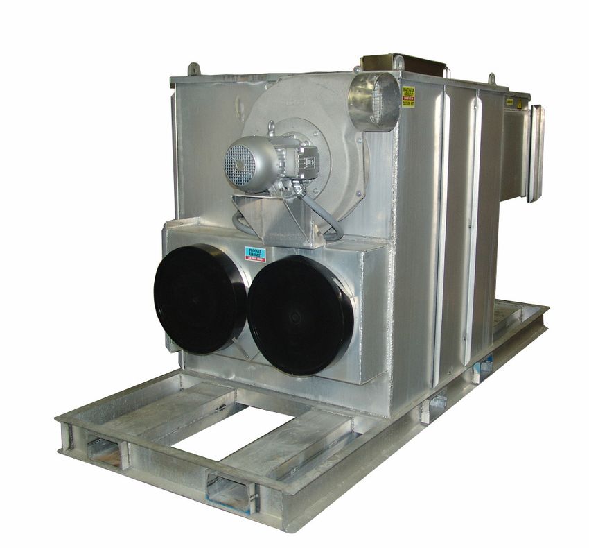
Phoenix 4800E
(with Frame)
PN 4034830
Phoenix 4800E
(without Frame)
PN 4034820
The Phoenix 4800E
• 3032 pints/day AHAM • 48”W x 120”L x 74”H
• 4800 CFM process airflow • 1600 lbs. (Standard
• Dries in temperatures to 140ºF machine weight only)
• Reaches dew points as low as -40ºF • 480 volt 3-phase
• 106 full load amps
TS-451
WISCONSIN Specifications subject to change without notice. 08/19 Rev. C
1.800.533.7533 USEPHOENIX.COM
1
Table of Contents
                                                                                                      1 Specifications
Introduction.................................................................................1
                                                                                                      Specifications for 4800E
1. Specifications......................................................................2
                                                                                                      Part No.       4034830 (with Frame)
2. Operation..............................................................................2
                                                                                                                     4034820 (without Frame)
     2.1 How the Phoenix 4800E Works ................................3                                               4034850 (with Frame Docking)
3. Installation...........................................................................3                          4034840 (without Frame Docking)
     3.1 Inspection......................................................................3            Power          480 VAC, 3-Phase, 106 FLA
     3.2 Location.........................................................................3
                                                                                                      Water          3032 pints/day @ AHAM
     3.3 Set-Up.............................................................................3
                                                                                                      Removal
     3.4 Ducting..........................................................................4
                                                                                                      Blower         4800 CFM Process Air Flow
     3.5 Avoiding Secondary damage......................................4
                                                                                                                     2000 CFM Reactivation Air Flow
     3.6 Electrical Requirements..............................................4
                                                                                                      Operating      -10ºF to 140ºF
4. Operation Instructions........................................................4
                                                                                                      Range
     4.1 Connect and Start-Up Procedure...............................4
                                                                                                      Filters        Process filter size: (2) 20” x 20” x 2”
     4.2 Cool Down.....................................................................5
                                                                                                                     Reactivation filter size: (1) 20” x 20” x 2”
     4.3 Shut Down and Disconnect Procedure.....................5
5. Control Panel.......................................................................5              Duct Options Process Inlet: 20” Flex-Duct
                                                                                                                   Process Outlet: 20” Flex-Duct/Lay Flat
     5.1 Main Disconnect...........................................................5
                                                                                                                   Reactivation Inlet: 20” Flex-Duct
     5.2 Standby Light................................................................5                            Reactivation Outlet: 10” Flex-Duct
     5.3 Phase Out......................................................................5
                                                                                                      Warranty       2 years:
     5.4 Selector Switch.............................................................5                               1st year Parts and Service
     5.5 Alarm (Light and Horn)................................................5                                     2nd year Silica Gel Rotor
     5.6 Hour Meter....................................................................5              Dimensions
6. Maintenance........................................................................5
                                                                                                                     Machine
     6.1 General Maintenance..................................................5
                                                                                                      Width          48”
     6.2 Cabinet..........................................................................5           Height         74”
     6.3 Filter...............................................................................5       Length         120”
     6.4 Blower and Motor.........................................................6                   Weight         1600 lb
     6.5 Drive Motor....................................................................6             Accessories
     6.6 Rotor Drive Chain.........................................................6
                                                                                                      4028365        Heavy Duty PVC/Polyester Duct 20” x 25’6” Pitch
     6.7 Seals..............................................................................6
                                                                                                      4035579        Heavy Duty PVC/Polyester Duct 20” x 25’4” Pitch
     6.8 Desiccant Media...........................................................6
7. Wiring Diagram...................................................................7                                NOTE: Duct with 4’ pitch is mandatory for the
                                                                                                                     return duct if you are recirculating.
8. Trouble Shooting.............................................................. 10
9. Detailed Sequence of Events......................................... 11                            4024440        Kestrel 3000 Multi-Function Air Meter
10. Service Parts List............................................................. 12                4027327        External Temperature control
11. Warranty............................................................................ 13
                                                                                                      4036662        External Dehumidistat

Serial No.__________________________________                                                          4029003        Power Cord Grip
                                                                                                      Air Filter Replacement
Purchase Date_____________________________
                                                                                                      4028635        20” x 20” x 2” Filter
Dealer’s Name_____________________________
Read the operation and maintenance instructions
carefully before using this unit. Proper adherence to these
instructions is essential to obtain maximum benefit from                                              2 Operation
your Phoenix 4800E.                                                                                   The function of the dehumidifier is to remove moisture (in
WARNING: **You are responsible to secure all doors and                                                the vapor state) from an air stream. This is accomplished
accessories during transit.**                                                                         by exposing the air to an adsorbing media (desiccant) in

  1.800.533.7533                                                                 USEPHOENIX.COM
                                                                                                  2
a sealed air stream (process). After the desiccant has
adsorbed moisture, it is exposed to a second air stream
3 Installation
at an elevated temperature (reactivation). This causes Proper installation is critical to the performance of the
the moisture to be driven out of the desiccant preparing Phoenix 4800E. Follow the guidelines below to maximize
it for more moisture adsorption. This process is done on a service life and performance.
continuous basis, providing a constant drying process. The
two air streams (process and reactivation) are separated 3.1 Inspection
by seals, which contact the desiccant media. Figure 1
Thoroughly inspect the machine to insure no damage has
illustrates the relationship of the seals and airflow pattern. occurred during shipping or on the job site.
The dehumidifier is designed with the two air streams
flowing in opposite directions (counter flow) thereby
maximizing the energy efficiency of the equipment. 3.2 Location
Note the following precautions when locating the Phoenix
Principle of Operation 4800E:
The 4800E is designed to be used indoors or outdoors.
Cabinet Divider If the humid area is very large, dehumidification can be
and Seals improved by adding an outlet duct to circulate process air to
stagnant areas.
Heater
Reactivation Air Outlet
Reactivation Air Inlet 3.3 Set-Up
When conditions warrant the use of a desiccant
Process Air Inlet dehumidifier, use one of the setups described below to
Process Air Outlet achieve efficient drying, while avoiding secondary damage.
Review Section 2.1 to understand the desiccant drying
process. Always ensure that the Reactivation Outlet duct
is vented to the outdoors to minimize the possibility of
secondary damage.
Desiccant Wheel
Desiccant Wheel Neutral Pressure Setup
Drive and Chain
Many drying applications require neutral pressure operation.
In this setup, the Process Air Inlet pulls air from the affected
2.1 How the Phoenix 4800E Works area (drying chamber) and returns dried, processed air to
the affected area via the Process Air Outlet.
The Phoenix 4800E has two separate air streams that run
through it – Process and Reactivation (Fig. 1).
The Reactivation Air Inlet and Outlet are both ducted to the
outdoors (or left open if the unit is set up outside).
Process Air Stream:
P1 – 4800 CFM of air enters the machine (Process Air Inlet) Positive Pressure Setup
and...
For Positive Pressure operation, the Process Air Inlet pulls
P2 – ...water vapor from incoming air is deposited air from outside the drying chamber, while the Process Air
(adsorbed) on the desiccant wheel. Outlet is ducted into the chamber.
P3 – 4800 CFM of dry air exits the machine (Process Air
Outlet). The Reactivation Air Inlet and Outlet are both ducted to the
outdoors (or left open if the unit is set up outside).
Reactivation Air Stream:
R1 – 2000 CFM of air enters the machine (Reactivation Air
Inlet) and...
R2 – passes over the heater coils.
R3 – Water vapor is picked up (desorbed) from the
desiccant wheel by the hot air and...
R4 – ... 2000 CFM of wet air exits the machine (Reactivation
Air Outlet).
1.800.533.7533 USEPHOENIX.COM
33.4 Ducting secondary water damage.
The duct requirements of the 4800E are much more critical The Phoenix 4800E does not produce liquid water internal
than those of refrigerant-based dehumidifiers. ALL SUPPLY to the machine. There is no condensate pump and no drain
AND RETURN AIR DUCTING FOR THE 4800E MUST BE AIR hose.
AND VAPOR TIGHT. This is extremely important for proper The 4800E desiccant dehumidifier will continue to remove
performance. Ensure that reactivation discharge air does water from already dry, cold air. It is possible to over-dry
not enter the process or reactivation inlets. objects and or structures.
Using excess duct length significantly reduces air flow Care must be taken to avoid secondary damage due to over-
volume through duct. This is true in any application. If the drying.
job at hand needs a short length of duct, cut a section to the
appropriate length. If air flow is restricted by excess length,
performance will suffer. The same can be said of excess 3.6 Electrical Requirements
bends in the ducting. A 480 volt, 3 phase power source is required to operate the
Two different duct sizes are used on the 4800E. All ducting Phoenix 4800E.
materials are available from Therma-Stor LLC
(see accessories list in Section 1).
All local and state codes must be strictly adhered to and
good electrical practices should be followed to achieve the
Process inlet / Reactivation inlet: 18” flex duct. best installation possible. The 4800E must be properly
To attach flex ducts to the process air intake, push the wire wired to an adequate power source. Serious damage to the
of the first few loops beyond the 2 holes in the duct collar. motors and controls can occur if incorrect voltage is applied.
Push the metal rod through the duct and duct collar piercing
the duct in two places. Tape or a hose clamp can be used (See Electrical Schematic drawing in the back of this
to create an airtight seal. Alternatively, the duct wire can be manual for internal wiring.)
pushed past the weld beads on the duct collar and the duct
can be secured with hose clamps or ratcheting straps. If
using only one inlet connection, the other can be left closed.
4 Operating Instructions
Process outlet: 18” flex or lay flat plastic duct. Refer to the Operating Instructions label located next to the
control panel of your 4800E.
To attach flex ducts to the process air outlet, push the wire
of the first few loops beyond the 2 holes in the duct collar.
Push the metal rod through the duct and duct collar piercing
the duct in two places. Tape or a hose clamp can be used
User-supplied power cord, cord grip, and branch protection
to create an airtight seal. Alternatively, the duct wire can be
pushed past the weld beads on the duct collar and the duct appropriate for the electrical load must be supplied. See
can be secured with hose clamps or ratcheting straps. device for FLA rating.
When using 18” lay flat ducting, slip over the outlet collar
and zip-tie or duct tape in place. The Phoenix 4800E dehumidifier comes complete and ready
for operation. All that is required is to provide the proper
Reactivation outlet: 10” flex duct. power source and duct connections (described above).
To attach flex duct to the reactivation air outlet, push the
wire of the first couple of loops beyond the weld beads on an
outlet collar. Secure with hose clamp. 4.1 Connect and Start-Up Procedure
1) Lockout Power Source.
2) Wire unit 480 Volt 3 Phase.
3.5 Avoiding Secondary Damage
3) Verify Selector Switch is set to STANDBY.
The Phoenix 4800E is a powerful tool capable of removing
a great deal of water from most environments. Care must 4) Engage Power Source and turn Main Disconnect to ON.
be taken to avoid secondary damage of over-drying and or 5) Verify PHASE OUT light is off, if not, re-wire power
unexpected condensation. source to correct phase order.
The Phoenix 4800E removes vapor water from the 6) COOL DOWN light will come on for 5 minutes.
incoming process air stream and transfers it to the outgoing 7) Set Selector Switch to RUN.
reactivation air stream. The reactivation exhaust air is hot
8) Set process damper to obtain a maximum of 1.5”
and wet.
water column pressure as read on pressure gauge.
Take care to prevent the reactivation exhaust air stream
from causing secondary damage due to condensation.
If the exhaust from reactivation air stream cools below its
dew point, liquid water will condense inside the duct work
creating puddles. If the reactivation exhaust air stream is not
exhausted completely from the structure it can also cause
1.800.533.7533 USEPHOENIX.COM
44.2 Cool Down 5.5 Alarm (Light and Horn)
1) Set Selector Switch to STANDBY. The alarm indicator lamp illuminates (and horn sounds) to
2) COOL DOWN light will come on for 5 minutes. indicate that a fault condition exists. The fault conditions
could be:
3) When COOL DOWN light is off, Main Disconnect can be
switched to OFF. • Motor Overload (process or reactivation)
• Reactivation Temperature greater than 375°F
• No dehumidification (i.e. saturated wheel)
Failure to follow COOL DOWN PROCEDURE may result in • Low reactivation airflow
damage to unit due to overheating. ALWAYS follow COOL • Stuck heater contactor
DOWN PROCEDURE before shutting unit down.
An external alarm can be wired to terminals 3080 (power)
4.3 Shut Down & Disconnect Procedure and X2 (neutral). This would supply 115 VAC during an
alarm condition.
1) Verify COOL DOWN light is not illuminated and
Cool Down Procedure has been followed. 5.6 Hour Meter
2) Turn Main Disconnect Switch to OFF. The hour meter will run whenever the 4800E is operating.
3) Disengage Power Source. This hour meter measures the cumulative time of operation
in one-tenth hour increments. This meter is often used to
4) Lock Out Power Source.
verify hours on a job or to schedule maintenance.
5) Disconnect Power Cable.
5 Control Panel 6 Maintenance
6.1 General Maintenance
5.1 Main Disconnect A definitive time schedule should be established for
The main disconnect switches power from the source to the inspecting all rotating parts and components. Inspection
panel. Power must be disconnected at the source prior to requirements depend on the frequency of operation,
accessing control panel. Access to the control panel with transport, and operating conditions. Periodically check
power applied is ONLY by qualified service personnel with the condition of the air filter, rotating parts, and fasteners
the appropriate personal protective equipment to ensure they are secure and in proper working order.
Periodically check airflow to make sure there are no
obstructions to airflow in outlet or inlet ductwork.
Power is present up to disconnect even in OFF position. Recommended minimum inspections:
Disconnect power at the source before opening panel. • Upon installation
• After 1 week of operation.
5.2 Standby Light • Annually thereafter or upon loss of performance.
The STANDBY indicator lamp illuminates to indicate that
power is supplied to the control panel. 6.2 Cabinet
5.3 Phase Out
The PHASE OUT indicator lamp illuminates to indicate that
Disconnect power before removing access panels.
the 3-phase power is not correctly wired into the power
supply. Change the wiring at the power supply connection to
correct the phase order. Remove panel fasteners and panels from unit to access
internal components. The condition of the cabinet gaskets
should be observed during inspection and servicing to insure
5.4 Selector Switch a good seal. Any leaks must be sealed and panels securely
When the selector switch is moved to the “RUN” position, fastened for proper dehumidifier operation.
the 4800E starts dehumidifying. The machine will continue
to dehumidify in all conditions until the power is turned off.
No dehumidistat is provided to monitor process inlet air 6.3 Filter
condition (see over-dry warning section 3.5). An external The maintenance interval for the filter depends directly on
control (dehumidistat, thermostat or other contact) can be the cleanliness of the air entering the dehumidifier. It is
wired in place of the jumper across terminals 3040 and suggested that a program be established to assure that the
3042. The external control must be designed to operate a filters are replaced or cleaned prior to becoming clogged to
115 VAC circuit. the point they create a system problem.
1.800.533.7533 USEPHOENIX.COM
5Three aluminum (20”x20”x2”) air filters must be checked and preventing contact with chemicals will greatly improve
regularly. Two filters are located near the process air inlet. the life of the desiccant. Inspect the face of the media to
The other one is located near the reactivation air inlet. see that no surface damage has occurred. If damage is
Wash the filters with fresh water. Clean the filter from the noticed, please contact Therma-Stor at 1-800-533-7533 for
downstream side, forcing debris toward the filter inlet. assistance. The rotor should turn smoothly upon the shaft, if
Dry the filters completely before installing them in unit. not check the support bearings.
Replacement filters can be ordered from the factory or
purchased locally if available.
DO NOT operate the unit without the filters or with less
effective filters as the desiccant wheel inside the unit will
Servicing the Phoenix 4800E with its high voltage
become clogged and require disassembly to clean.
circuitry presents a health hazard which could result in
death, serious bodily injury, and/or property damage. Only
6.4 Blower and Motor qualified service people should service this unit.
Blower and motor bearings are permanently lubricated and
do not require maintenance. Blower wheel - inspect wheel
blades for accumulation of dust and dirt. Clean thoroughly
with compressed air and or vacuum. The wheel should
ELECTRICAL SHOCK HAZARD: Electrical power must be
not strike the housing or the inlet ring. Make sure wheel is
present to perform some tests; these tests should be
rotating in the proper direction.
performed only by a qualified service person.
6.5 Drive Motor
The media drive motor is permanently lubricated and
requires no maintenance.
6.6 Rotor Drive Chain
A spring loaded tensioner keeps the chain sufficiently
tensioned. Check the chain for signs of excessive wear.
Replace as necessary. If additional tension is required,
simply tighten the nuts on the tension springs as required.
6.7 Seals
High temperature seals separate the process and
reactivation compartments. Normally, the seals will not
require service or replacement. However, should damage
occur, or if poor performance as the result of an air leak is
suspected, the following inspection must be performed to
determine whether the seals should be replaced:
Inspection:
1) Turn the unit off and remove the access covers.
2) Visually inspect for gaps between the desiccant media
and the seals.
3) If significant gaps, wear, or damage are observed,
the seal needs to be replaced.
6.8 Desiccant Media
The silica gel desiccant media supplied with the
dehumidifier will last indefinitely under ideal conditions.
Due to the nature of desiccants they make very good filters.
The life of the desiccant is directly related to the airborne
contaminates passed through it. Atmospheric contaminants,
exposure to acidic gases/or air streams, and contact with
petroleum based airborne particles can reduce the efficiency
of the desiccant media. The preferred method of cleaning
is to blow dust out with compressed air. Proper filtration
1.800.533.7533 USEPHOENIX.COM
67 Panel Layout/Wiring
Diagram
1.800.533.7533 USEPHOENIX.COM
77 Panel Layout/Wiring
Diagram
480V 3Ø 60HZ
INCOMING POWER
GND LL1 LL2 LL3
NON-FUSED DISCONNECT POWER DISTRIBUTION
200 AMP
BRANCH PROTECTION SUPPLIED
**(BY OTHERS)**
105 FLA
LARGEST MOTOR 7.5HP
LARGEST HEATER 24KW
#8 AWG PER PHASE #8 AWG PER PHASE FIELD DETERMINE
L1 L2 L3 TYPE MTW TYPE MTW
90 DEG C COPPER 90 DEG C COPPER
1CB HAR 1T1
L1 1L1
1T2 HEATER A
L2 1L2
24 KW
1T3 28.9FLA
L3 1L3
40A
#8 AWG PER PHASE #8 AWG PER PHASE FIELD DETERMINE
TYPE MTW TYPE MTW
90 DEG C COPPER 90 DEG C COPPER
2CB HBR 2T1
L1 2L1
2T2 HEATER B
L2 2L2
24 KW
2T3 28.9FLA
L3 2L3
40A
#8 AWG PER PHASE #8 AWG PER PHASE FIELD DETERMINE
TYPE MTW TYPE MTW
90 DEG C COPPER 90 DEG C COPPER
3CB HCR 3T1
L1 3L1
3T2 HEATER C
L2 3L2
24 KW
3T3 28.9FLA
L3 3L3
40A
#14 AWG PER PHASE #14 AWG PER PHASE FIELD DETERMINE
TYPE MTW TYPE MTW
90 DEG C COPPER 90 DEG C COPPER
OLR-P PMS 4T1
L1 4L1
4T2 PROCESS MOTOR
L2 4L2 7.5HP
PMS
3600 RPM
4T3 10.9FLA
L3 4L3
(9.0-12.5A)
SET AT 10.9A FIELD DETERMINE
#14 AWG PER PHASE #14 AWG PER PHASE
TYPE MTW TYPE MTW
90 DEG C COPPER 90 DEG C COPPER
OLR-R RMS 5T1
L1 5L1
5T2 REACTIVATION MOTOR
L2 5L2 5HP
RMS
3600 RPM
5T3 6.1FLA
L3 5L3
(6.3-9.0A)
SET AT 6.3A
#14 AWG PER PHASE
TYPE MTW
90 DEG C COPPER
L1
3
L2
4 PHASE
L3
MONITOR
5
#14 AWG PER PHASE
TYPE MTW
90 DEG C COPPER
L1 FU1 XL1
L2 FU2 XL2
480VAC XFMR
2A H3 H2 350VA
#14 AWG MTW RED
H1 H4 #14 AWG MTW WHITE
1 1 FU3 2
120VAC
X1 X2
4A
#14 AWG MTW GRN/YEL
L1 L2
TO SHEET 3 OF 3 TO SHEET 3 OF 3
1.800.533.7533 USEPHOENIX.COM
87 Panel Layout/Wiring
Diagram
1.800.533.7533 USEPHOENIX.COM
99 Troubleshooting
8 Trouble Shooting
Trouble Probable Fault Probable Cause Corrective Action
Unit Stopped Power/Control 1. Main power off Check main power and cable
(fan off, no Failure 2. Main disconnect open Close or replace disconnect
heater) 3. Selector switch open Close or replace switch
4. Dehumidistat Repair or replace
Fan off Power/Mechanical 1. Motor circuit breaker or Reset circuit breaker or
(Rotor turns) Failure overload tripped overload
2. Contactor failure Repair or replace
3. Motor winding failure Repair or replace
4. Fan motor failure Repair or replace
Unit running Excessive 1. Excessive unconditioned make- Reduce make-up air
but humidity infiltration of up air
rises humid air into the 2. Leaking ducts or air handling Seal leaks
controlled area equipment outside controlled
area
3. Access opening to area not Close and seal
sealed
4. Area not vapor tight Seal with paint or vapor barrier
Faulty humidity 1. Dehumidistat needs Re-adjust
controls adjustment
2. Improper settings Re-adjust
3. Defective Replace
Inadequate air flow 1. Dirty filter Clean or replace
2. Obstruction at inlet, outlet or Remove obstruction
ducting
3. Clogged desiccant media Remove and replace media
(high pressure differential rotor
across media)
Inadequate or no 1. Element failure Check elements – repair or
reactivation heat replace
2. Low / no voltage Correct power supply /
breakers
3. Control elements failure Control set point / repair or
replace
Air seals and 1. Air leaking into dehumidifier Replace access door gaskets
gaskets 2. Air bypassing media or leaking Check media position, replace
seals seals
Ineffective 1. Chain Repair or replace
desiccant media 2. Motor/gear box Repair or replace
3. Damaged desiccant rotor Repair or replace
4. Contaminated or damaged Replace desiccant rotor
desiccant
1.800.533.7533 USEPHOENIX.COM
109 Detailed Sequence of Events auxiliary contact, energizing the latching alarm
relay AR.
– Control Operation a) ALARM lamp illuminates.
b) Alarm horn sounds.
1) Turning on Main Disconnect at dehumidifier provides c) Terminals 3080 and X2 energize. These
480 VAC, 3 phase power to the control panel. Power is terminals can be utilized for an external alarm
distributed to breakers for blower motors, heaters and (1 amp maximum).
the control transformer. The control transformer d) Time relay TR1 starts the 5 minute heater cool
supplies 115 VAC for control system and desiccant down cycle. Following the delay…
wheel motor. I) TR1 relay energizes, opening contacts for the
a) PHASE OUT lamp, if illuminated, indicates the COOL DOWN light and reactivation blower
power supply is not connected correctly. Rewire motor starter (RMS). Rotor motor terminals
power supply as needed. 3470 and X2 de-energize.
b) STANDBY lamp illuminates. Reset alarm by turning the selector switch to
c) Rotor motor terminals, 3470 and X2, energize STANDBY.
providing the desiccant motor with 115 VAC power. Probable causes for a high temperature fault are
Desiccant wheel begins to rotate. reduced air flow, dirty filter, incorrect reactivation
d) Reactivation motor starter RMS contacts close, blower rotation, or blower failure.
starting the reactivation blower. 4) On a fault from an overload relay (OLR-P or OLR-R), the
e) COOL DOWN light illuminates, indicating the timed latching alarm relay (AR) energizes. The effect is listed
heater cool down cycle has started. in lines 3a through 3d.
f) Time relay TR1 starts the 5 minute heater cool Turn the selector switch to STANDBY, allowing the
down cycle. Contacts are normally closed, timed cool down cycle to complete before turning OFF the
open (NCTO). Following the delay… main disconnect. Follow Lock Out – Tag Out procedure
to de-energize the power cord supplying the 4800.
I) TR1 relay energizes, opening contacts for the
Reset the overload relay located in the control
COOL DOWN light and reactivation blower
cabinet. Close and secure cabinet door. Energize unit
motor starter (RMS). Rotor motor terminals
following proper Lock Out – Tag Out procedure.
3470 and X2 de-energize.
Probable causes for a fault from an overload relay
Note: The cool down cycle can be interrupted if the are insufficient restriction of airflow (overloading motor
RUN position is selected and no alarm conditions are by allowing excessive airflow) or blower/motor failure.
present.
5) On a fault from the internal process dehumidistat
that persists for 20 minutes, the latching alarm relay
2) Selecting the RUN position (selector switch) … (AR) energizes. The effect is listed in lines 3a through
a) Provides power to the temperature control TC. 3d. TDR1 provides a 10 minute delay for the removal
of residual humidity desiccant during startup.
b) Start relay SR energizes, if no alarm conditions
are present (AR relay de-energized) Reset alarm by turning the selector switch to
STANDBY.
I) Time relay TR1 and COOL DOWN light
de-energize. Run indicator illuminates. Probable causes for a fault from the internal
Reactivation blower motor starter is energized. dehumidistat are heater failure or desiccant failure.
Pressure switch PS1 is activated when 6) On a fault from a stuck heater contactor, the Alarm
reactivation airflow reaches minimum level. Relay will energize and the reactivation blower will
II) TDR2 starts a 20 second delay followed remain on continuously. The Rotor will continue to turn,
by energizing Process motor start (PMS), hour but the process blower will NOT come on. Shut off power
meter, and TDR4 40sec timer. If pressure with the main disconnect and replace the inoperable
switch PS1 was not activated in previous step contactor to clear the error.
due to lack of airflow, Alarm relay is energized
and unit is not allowed to run. No dehumidistat is provided to monitor process inlet
III) Heater “A” Relay HAR energizes, if auxiliary air condition (see over-dry warning section 3.5). An
contacts of the reactivation motor overload external control (dehumidistat, thermostat or other
(RMS) are closed and the temperature control dry contact) can be wired in place of the jumper across
is calling for heat. terminals 1 and 3082. The external control must be
IV) Upon TDR4 reaching 40seconds, remaining designed to operate a 115 VAC circuit. Contact closure
heat contactors HBR and HCR are energized will start dehumidification. A control wired across
terminals 1 and 3082 will be in series with the selector
3) If temperature in reactivation heater plenum exceeds
switch. Turn the selector switch to RUN to operate the
375°F, the temperature control TC will close its
dehumidifier from an external control.
1.800.533.7533 USEPHOENIX.COM
1110 Service Parts
Item Part No. Qty. Description
1 4027228 1 Blower, Reactivation, 460V, 5HP
2 4027229 1 Blower, Process, 460V, 7.5HP
3 4028630 1 Probe, Thermocouple, Type J, 12”
4 4028633 3 Heating Element, 24KW
5 4036662 1 Dehumidistat
6 4028771 1 Temperature Controller with
Control Output Board, Relay SPST
7 4032306 1 Control Box
8 4030198 2 Fusa 2A
9 4030199 1 Fuse 4A
1.800.533.7533 USEPHOENIX.COM
124201 LIEN RD. • MADISON, WI 53704
Phoenix 4800 Desiccant Dehumidifier
LIMITED WARRANTY
Warrantor:
Therma-Stor LLC
4201 Lien Rd
Madison, WI 53704
Telephone: 1-800-533-7533
Who Is Covered: This warranty extends only to the original end-user of the 4800 and may not be
assigned or transferred.
First Year Warranty: Therma-Stor Products warrants that, for one (1) year the 4800 will operate free
from any defects in materials and workmanship, or Therma-Stor Products will, at its option, repair or
replace the defective part(s), free of any charge.
End-User Responsibilities: Warranty service must be performed by a Servicer authorized by Therma-Stor
Products. If the end-user is unable to locate or obtain warranty service from an authorized Servicer, he
should call Therma-Stor Products at the above number and ask for the Therma-Stor Products Service
Department, which will then arrange for covered warranty service. Warranty service will be performed
during normal working hours.
The end-user must present proof of purchase (lease) upon request, by use of the warranty card or
other reasonable and reliable means. The end-user is responsible for normal care. This warranty does
not cover any defect, malfunction, etc. resulting from misuse, abuse, lack of normal care, corrosion,
freezing, tampering, modification, unauthorized or improper repair or installation, accident, acts of
nature or any other cause beyond Therma-Stor Products’ reasonable control.
Limitations and Exclusions: If any 4800 part is repaired or replaced, the new part shall be warranted for
only the remainder of the original warranty period applicable thereto (but all warranty periods will be
extended by the period of time, if any, that the 4800 is out of service while awaiting covered warranty
service).
UPON THE EXPIRATION OF THE WRITTEN WARRANTY APPLICABLE TO THE 4800 OR ANY PART
THEREOF, ALL OTHER WARRANTIES IMPLIED BY LAW, INCLUDING MERCHANTABILITY AND FITNESS
FOR A PARTICULAR PURPOSE, SHALL ALSO EXPIRE. ALL WARRANTIES MADE BY THERMA-STOR
PRODUCTS ARE SET FORTH HEREIN, AND NO CLAIM MAY BE MADE AGAINST THERMA-STOR PRODUCTS
BASED ON ANY ORAL WARRANTY. IN NO EVENT SHALL THERMA-STOR PRODUCTS, IN CONNECTION
WITH THE SALE, INSTALLATION, USE, REPAIR OR REPLACEMENT OF ANY 4800 OR PART THEREOF
BE LIABLE UNDER ANY LEGAL THEORY FOR ANY SPECIAL, INDIRECT OR CONSEQUENTIAL DAMAGES
INCLUDING WITHOUT LIMITATION WATER DAMAGE (THE END-USER SHOULD TAKE PRECAUTIONS
AGAINST SAME), LOST PROFITS, DELAY, OR LOSS OF USE OR DAMAGE TO ANY REAL OR PERSONAL
PROPERTY.
Some states do not allow limitations on how long an implied warranty lasts, and some do not allow the
exclusion or limitation of incidental or consequential damages, so one or both of these limitations may
not apply to you.
Legal Rights: This warranty gives you specific legal rights, and you may also have other rights which vary
from state to state.
1.800.533.7533 USEPHOENIX.COM
13You can also read