Silicon Carbide Schottky Barrier Diodes - White Paper
←
→
Page content transcription
If your browser does not render page correctly, please read the page content below
Innovations Embedded

Silicon Carbide
Schottky Barrier Diodes

                                         White Paper
ROHM MarketingUSA                    Presented by ROHM Semiconductor
Silicon Carbide
                                              Schottky Barrier Diodes
                           Taking Efficiency to the Next Level for PFC and Other Applications

Introduction                                                                                 Schottky barrier diodes (SBDs) have been available for
                                                                                             more than a decade but were not commercially viable
The semiconductor industry has a well-established
                                                                                             until recently. As a pioneer in SiC technology, ROHM
history of “smaller, faster, and cheaper.” Improving
                                                                                             Semiconductor expects that volume production will lead
performance and reducing device cost while shrinking
                                                                                             to SiC’s acceptance in more and more applications.
packaging size is fundamental to virtually every semi-
conductor product type. For power products, improved
                                                                                             The Advantages of Silicon Carbide
performance is measured by increased efficiency and
power density, higher power handling capability, and                                         The highest performance silicon power diodes are
wider operating temperature range. Such improvements                                         Schottky barrier diodes. Not only do SBDs have the
depend largely on the desirable characteristics of power                                     lowest reverse recovery time (trr) compared to the
components used, such as low switching and conduc-                                           various types of fast recovery (fast recovery epitaxial),
tion losses, high switching frequency, stable electrical                                     ultrafast recovery and super-fast recovery diodes, they
characteristics over a wide temperature range, high                                          also have the lowest forward voltage drop (VF). Both of
operating temperature, and high blocking voltage. As                                         these parameters are essential to high efficiency. Table
silicon power components approach their theoretical                                          1 shows a comparison of breakdown voltage, VF, and
limits, compound semiconductor materials, such as sili-                                      trr for commonly available diodes. While Schottky bar-
con carbide (SiC) and gallium nitride (GaN), provide the                                     rier diodes have the advantage of low forward losses
capability to dramatically improve these parameters.                                         and negligible switching losses compared to other diode
                                                                                             technologies, the narrow bandgap of silicon limits their
Today, the need for higher efficiency in end products is
                                                                                             use to a maximum voltage of around 200 V. Si diodes
more critical than ever. Although silicon power products
                                                                                             that operate above 200 V have higher VF and trr.
continue to see incremental improvements, devices
based on compound semiconductor materials deliver                                            Silicon carbide is a compound semiconductor with
significantly better performance — in a large number of                                      superior power characteristics to silicon, including a
cases not possible with their silicon counterparts. This is                                  bandgap approximately three times greater, a dielectric
certainly true for the most basic components in power                                        breakdown field 10 times higher and a thermal coef-
electronics: diodes and transistors. Silicon carbide (SiC)                                   ficient three times larger. These characteristics make it

                                 Type                                          VBR (VRRM)                                  VF (1)         trr (1)
                     Si Schottky Barrier Diode                                    15 V-200 V                             0.3V-0.8 V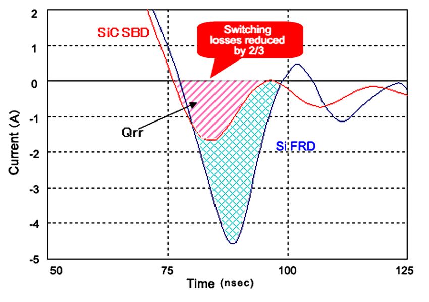
ideal for power electronics applications. Silicon carbide
devices have higher breakdown voltage, operating tem-
perature and thermal conductivity, as well as shorter
recovery time and lower reverse current than silicon
diodes with comparable breakdown voltage. These
device characteristics equate to low-loss, high-efficiency
power conversion, smaller heat sinks, reduced cooling
costs and lower EMI signatures. Continuing progress in
raising high (250º C+) operating temperature and high
blocking voltage promise exciting new applications such
as motor drive in HEV/EV and solid-state transformers.
Figure 1. With an SiC Schottky barrier diode (SBD), switching losses
SiC is certainly not the only compound semiconductor are reduced by 2/3 compared to a silicon fast recovery
diode (FRD). The Si FRD is used for comparison since it
material being considered for next-generation power
has a comparable voltage rating to the SiC SBD.
components. Gallium arsenide (GaAs) Schottky rectifiers
have been available since the 1990s but have only found
limited acceptance for the most demanding applications
due to their higher cost than silicon. GaAs bandgap,
breakdown field and thermal conductivity are lower than
silicon carbide. More recently, researchers are pursuing
gallium nitride (GaN) for power transistors. GaN has sim-
ilar bandgap and dielectric constant (hence comparable
breakdown voltage) to SiC. It has higher electron mobil-
ity but only ¼ the thermal conductivity. This technology
is early in its development/commercialization phase rela-
tive to SiC. Currently there are many more SiC devices
and suppliers.
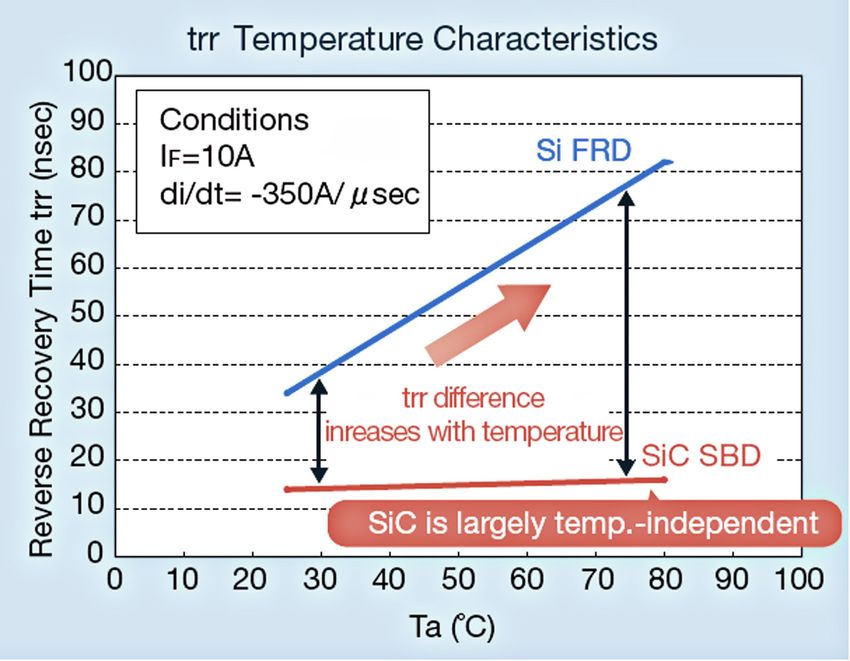
Figure 2. The reverse recovery time of a silicon FRD can easily
double with a junction temperature rise of only 40°C. In
Figure 1 shows the reduction in switching losses com- contrast, silicon carbide SBDs are essentially flat over this
pared to fast recovery diodes based on SiC SBD’s mini- same temperature range.
mal reverse recovery charge (Qrr) during turn-off.
With all of these benefits, why hasn’t SiC had more of
With silicon fast recovery diodes, the trr increases sig- an impact in new products? One reason is the continu-
nificantly with temperature as shown in Figure 2. In ous improvements of silicon devices, which benefits
contrast, SiC SBDs maintain a constant trr regardless of from having an infrastructure – process, circuit design,
temperature. This enables SiC SBD operation at higher production equipment – that has been fine tuned for
temperature without increased switching losses. The over fifty years. By contrast, SiC technology is still in
numerous SiC SBD performance advantages can result its infancy. The higher cost of SiC devices has been a
in more compact, lighter power devices with higher effi- barrier to most commercial applications. This is due in
ciency. large part to the fact that SiC is a much more difficult
SiC has demonstrated temperature stability over a wide material to process than silicon. For example, costly ion
operating range, as shown in Figure 3. This simplifies implantation is used for doping because of SiC’s low
the parallel connection of multiple devices and prevents diffusion rate. Reactive ion etching (RIE) with a fluorine-
thermal runaway. based plasma is performed, followed by annealing at
ROHM Semiconductor SiC Schottky Barrier Diodes 2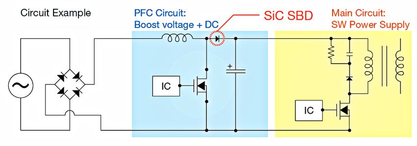
n   lower production costs;
                                                                                                      n   availability of SiC transistors;
                                                                                                      n   wider pool of suppliers;
                                                                                                      n   the rise of green energy in general, and power
                                                                                                          conversion efficiency in particular, driven by
                                                                                                          legislation and market demands; and
                                                                                                      n   new applications such electric vehicles (EVs) and
                                                                                                          charging stations.

                                                                                                   Cost

                                                                                                 In its report “SiC 2010,” Yole Developpement identified
Figure 3. The forward voltage of a high voltage (1200V) silicon car-                             the transition to 4-inch (100-mm) SiC wafers as a signifi-
          bide SBD increases less than 2X when the temperature
          increases from 25°C to 225°C.                                                          cant milestone towards reduced cost. The report states,
high temperature. These processing difficulties increase                                         “The total SiC substrate merchant market has reached
cost and limit the types of device structures that can be                                        approximately $48M in 2008. It is expected to exceed
built. As a result, the cost is high and availability limited.                                   $300M in a decade.” The coming transition to 6-inch
However, this is about to change.                                                                (150-mm) wafers is expected to play a significant role
                                                                                                 in further cost reduction and market growth. According
The Timing is Right for Silicon Carbide                                                          to the report, “150-mm wafers will definitely accelerate
Technology                                                                                       the cost reduction of SiC device manufacturing.” Figure
                                                                                                 4 shows the growth that can be expected for SiC sub-
Though the first commercial SiC SBDs were available
                                                                                                 strates in photovoltaic (PV) inverters, a key application
in 2001, adoption has been limited until recently. The
                                                                                                 requiring high efficiency.
increase in interest and adoption in many applications
are predominantly due to:

                                        SiC Substrate Market in Units and $ for PV Inverters
         Substrate volume (units)

                                                                                                                                                            Substrate market (M$)

                                                                                  SiC 6” wafer (units)
                                                                                  SiC 4” wafer (units)
                                                                                  Wafer market (M$)

                                        2006        2007       2008        2009       2010        2011        2012       2013        2014        2015

                                    Figure 4. Increased wafer sizes of 4 and 6-inch will accelerate market acceptance of SiC. Source: Yole Developpement.

ROHM Semiconductor                                                           SiC Schottky Barrier Diodes                                                                            3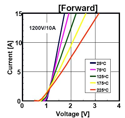
Diode + Transistor (Si + SiC) Device Market in PV Inverters
        Device market (M$)

                                             Si market (M$)
                                             SiC market (M$)

                             2008   2009   2010    2011       2012    2013      2014       2015      2016      2017      2018      2019

     Figure 5. SiC diodes and transistors will start to grow in photovoltaic inverter applications starting in 2013. Source: Yole Developpement.

  SiC Transistor                                                             California’s Renewables Portfolio Standard (RPS), estab-
                                                                             lished in 2002 under Senate Bill 1078, is one of the most
One of the main obstacles to the increased use of SiC
                                                                             ambitious renewable energy standards in the country.
has been the lack of an SiC transistor to provide a com-
                                                                             It requires that 20% of a utility’s portfolio should come
plete SiC solution. With the ongoing global R&D efforts
                                                                             from renewable energy by 2017. These and other efforts
in this area, Yole expects to see volume production
                                                                             will drive the need for SiC PV inverters.
within the next few years. Figure 5 shows the impact this
will have in one market – photovoltaic converters. The                       Other applications that are attracting early adopters of
growth is based on a greater number of suppliers and                         SiC technology and seeing early implementation include
increased production capacity for both SiC diodes and                        those where the need for high efficiency is either a major
transistors.                                                                 end-product differentiator and/or where legislation and
                                                                             regulations dictate a minimum energy efficiency level.
  Legislation and Market Push for Green Energy                               Some key regulatory milestones are:
Governments around the globe are pursuing renewable                              n     January 2001, IEC-61000-4-3 requirements stimu-
energy sources to reduce the dependence on fossil fuels                                late active power factor correction (PFC) to mini-
and reduce CO2 emissions. For example, in the U.S.,                                    mize energy loss and distortion in AC/DC switch
President Obama has set a goal of generating 80% of                                    mode power supply (SMPS) designs (see Figure
America’s electricity from clean sources by 2035.                                      6). Many power products are required to meet

   Figure 6. A simplified active PFC boost converter typically requires a power MOSFET, a blocking diode, an inductor and a capacitor. Not
             shown is a snubber circuit to mitigate EMI emission.

ROHM Semiconductor                                        SiC Schottky Barrier Diodes                                                              4
80 PLUS Test Type 115V Internal Non-Redundant 230V Internal Redundant
Percent of Rated Load 20% 50% 100% 20% 50% 100%
80 PLUS Basic 80% 80% 80% Not defined
Bronze 82% 85% 82% 81% 85% 81%
Silver 85% 88% 85% 85% 89% 85%
Gold 87% 90% 87% 88% 92% 88%
Platinum 90% 92% 89% 90% 94% 91%
Table 2. 80 PLUS Efficiency Levels. Per ENERGY STAR 5.0, desktop computer, laptop computer or server power supplies must comply with
the Bronze level. Source: Wikipedia.
both minimum power factor and efficiency levels. As a practical example, consider the PFC circuit
n In 2004, the 80 Plus program was launched that in a 1 KW AC-DC power supply with the following
requires 80% or higher energy efficiency at various characteristics:
loads (see Table 2). SiC SBDs allow power supply n Input: 100 Vac, 60 Hz
designers to meet high efficiency certification lev- n Output: 400 Vdc, 2.5 A
els such as 80 Plus Bronze, Silver, or Gold. n Switching frequency: 50 KHz
n In July 2009, the U.S. Department of Energy n Operating temperature: 100º C
(DOE) ENERGY STAR v5.0 specification for com-
Tabel 3 summarizes the performace comparison
puters that includes 80 Plus power supply effi-
between a circuit using a 600V Si FRD and an SiC SBD.
ciency was adopted by the European Commission
and the U.S. government. Si-FRD ROHM SiC SBD
Peak reverse current 56 A 14 A
SiC advantages in real-world applications Power conversion efficiency 93.13% 95.57%
Harmonic distortion 2.42% 2.36%
SMPSs with output power ratings above 300 W typically
Table 3. Performance comparison between circuits using 600 V / 20 A
use active PFC boost converters designed to operate Si-FRD and ROHM 600 V / 10A SBD (SCS110AG).
in continuous conduction mode (CCM). The single big-
gest advantage of using SiC diode in place of Si diode is Improvements similar to those in power supplies and
the former’s much lower reverse recovery current (See PFC circuits can be obtained in other applications. For
Figure 1), which translates into approximately 60% lower example, inverters with SiC SBDs have dramatically
switching loss and elimination (or great simplication) of reduced recovery losses, resulting in improved efficiency.
the snubber circuit to control EMI. Also, the switching When used with IGBTs and lower operating frequencies,
transistor no longer has to be derated to accommodate the lower thermal losses allow for smaller heat sinks.
the large reverse current from the silicon blocking diode
Using ROHM’s SiC SBDs, customers report improve-
— a lower amperage, less expensive transistor can be
ments of system-level efficiency from 0.3% to 1.0%.
used. With lower loss, the heat sink/cooling system can
This translates into an annual savings of over $50 for
be made smaller. Lower switching loss allows the circuit
a 20 kW inverter operating at a cost of $0.10/kW-hr.
to operate at higher frequency giving designers options
For products with a long lifetime such as such as solar
to further increase efficiency and/or to reduce the
inverters, this provides a savings of $750 in 15 years or
choke’s size, saving cost and board space.
$1500 in 30 years.
ROHM Semiconductor SiC Schottky Barrier Diodes 5100000
50000
Medium voltage High voltage
resistance devices resistance devices
10000
5000 Energy transmission
and distribution PE
Rated Current (A) 1000
Low voltage
HEV
resistance devices EV Railway drive
500
Package Industrial motors
100 Air conditioners
50
DC/DC Automotive
Converter equipment
Routers
SiC device
10 Power supplies
Notebook PCs HDD for communication
Server WS target market
5 devices AC adapters
PPC SW power supplies
1
10 50 100 500 1000 5000 10000 50000 100000
Rated Voltage (V)
Figure 7. Target applications for silicon carbide’s higher efficiency vary depending on voltage and current rating.
In addition to photovoltaic inverters and PFC, other transistors (MOSFETs, JFETs, BJTs), SiC diodes pack-
applications for 600 V and lower SiC devices include aged with Si transistors, SiC module, etc.
switching circuits, uninterruptible power supplies (UPS),
A rapidly emerging field that can dramatically accelerate
motor drive circuits, and others where high efficiency
the need for SiC are vehicles with some form of electric
is a product differentiator. Figure 7 shows how various
propulsion such as hybrid, plug-in hybrid, electric, and
application areas are distributed according to block-
fuel cell vehicles. Efficiency, size, and cost are extremely
ing voltage and current handling requirements. Though
important factors, making SiC devices particularly suit-
today’s SiC devices still trail IGBT in power rating and
able. These vehicles require the efficiency that SiC can
the types of devices are still limited, in general the higher
provide and, equally important, they have an operating
these requirements are, the more compelling the adop-
environment that demands SiC’s temperature stability
tion of SiC technology.
and higher temperature operating capabilities. Cars with
SiC SBDs and SiC transistors can potentially eliminate a
Challenges to SiC adoption
liquid cooling system to help justify the increased costs
The main obstacles to widespread adoption of SiC are of SiC technology. Acceptance in these vehicles will cre-
cost, availability (of different device types as well as a ate a high volume damand and push the technology into
larger supplier pool) and familiarity of the engineering the mainstream.
community with this technology.
While EV usage will occur in the future when SiC tran-
For SiC components to be widely adopted in power sistors are more affordable and widely available, having
electronics, the premium over Si must come down. SiC them as a driving force should encourage engineers with
diodes are approximately 5x more expensive than Si other applications to take a closer look at SiC technol-
FRDs. As with silicon, lower costs will be reailzed by ogy.
improving yield as the technology matures, the use of
As described earlier in the PFC application example, SiC
larger wafers, and an increase in the number of suppli-
can in many cases serve as a drop-in replacement for its
ers. In the past few years, more vendors — both small
Si counterpart. This example also makes it clear that, to
and large, startups and established - have joined the
fully realize the performance benefits and potential cost
“race.” As a result, a variety of SiC devices are or will
savings, (e.g., no or simplified snubber, using switching
soon be available, including various flavors of diodes and
ROHM Semiconductor SiC Schottky Barrier Diodes 6transistor with lower current rating), designers must be ROHM has also solved the problems associated with
fully aware of the characteristics of SiC devices. Those mass production of SiC SBD devices, such as uniformity
who take advantage of SiC’s capabilities early, when of the Schottky contact barrier and formation of a high-
only diodes are widely available, will be in a much better resistance guard ring layer that does not require high
position to judge, adopt, and fully realize the benefits of temperature processing, making uniform, in-house pro-
future SiC components (transistors, modules, etc.) in duction possible.
power applications.
In 2008, ROHM together with Nissan Motor Co., Ltd.
announced the development of a heterojunction diode
ROHM Semiconductor’s Silicon Carbide
(HJD). The HJD delivers avalanche energy and fracture
Solutions
resistance that exceed the performance of previous
As a leading designer and manufacturer of semiconduc- designs by a factor of 10. ROHM had been shipping
tor products, from VLSI integrated circuits to discretes HJD engineering samples along with proprietary high-
and passives to optical electronics, ROHM recognized power SBDs and MOSFETs for two years prior to the
the potential of and made significant investment in sili- announcement. During that time, engineers worked
con carbide technology many years ago. Some of the aggressively to improve the underlying technologies for
major milestones in its history of silicon carbide research commercialization.
and development have been announced and are worth
In 2010, ROHM acquired SiCrystal AG, a leading pro-
noting.
ducer and supplier of high-quality, single-crystalline
ROHM’s pioneering efforts resulted in the successful silicon carbide wafers. SiCrystal’s capabilities include
development of a silicon carbide double-diffusion metal- complete materials processing from crystal growth to
oxide-semiconductor field-effect transistor (DMOSFET) wafering. With the acquisition of SiCrystal AG, ROHM
prototype in 2004. Schottky barrier diodes and power possesses total manufacturing capability for SiC semi-
modules that incorporated SiC transistors and SBDs conductors from ingot formation to power device fabri-
were developed soon afterward. Improvements and cation. This allows the rapid development of advanced
enhancements were made to the SiC SBDs based on products and complete control of raw materials for
customer feedback in 2005. This led to the development industry-leading reliability and quality.
of a uniform production system for SiC devices.
ROHM’s R&D activities also include the development of
Mass production of SiC transistors has proven particu- the industry’s first SiC Trench MOSFET as well as high
larly challenging to manufacturers worldwide. Therefore, power modules using SiC Trench MOSFETs and SBDs
in parallel, ROHM partnered with university and industrial compatible with operating temperatures greater than
partners to develop production processes and equip- 200° C.
ment. ROHM overcame several significant obstacles
ROHM’s SiC offerings include Schottky barrier diodes,
and successfully established the industry’s first mass
MOSFETs, and modules. 600 V SBDs are in mass pro-
production system for SiC transistors. To do this, ROHM
duction and are available as bare die or packaged parts.
developed a proprietary field-weakening architecture
1200 V SBDs and MOSFETs are currently sampled to
and unique screening methods to ensure reliability and
customers in North America. In the pipeline are paired
technology that limits the degradation in characteristics
SiC SBD plus Si transistor in a single package as well as
caused by the high-temperature (up to 1,700° C) pro-
all-SiC modules.
cesses required in SiC fabrication.
ROHM Semiconductor SiC Schottky Barrier Diodes 7Absolute Maximum Ratings Electrical Characteristics
(Ta = 25°C) (Ta = 25°C)
Part No. Package
IFSM(A) VF(V) IR(µA)
VRM(V) VR(V) IO(A)
60Hz.1 Typ. IF(A) Max. VR(V)
SCS106AGC 600 600 6 24 1.5 6 120 600 TO-220AC [2 pin]
SCS108AGC 600 600 8 32 1.5 8 160 600 TO-220AC [2 pin]
SCS110AGC 600 600 10 40 1.5 10 200 600 TO-220AC [2 pin]
SCS112AGC 600 600 12 48 1.5 12 240 600 TO-220AC [2 pin]
SCS120AGC 600 600 20 80 1.5 20 400 600 TO-220AC [2 pin]
Table 4. Available Schottky barrier diodes range from 6A to 20A-rated 600V products.
ROHM Semiconductor Silicon Carbide At higher temperatures, ROHM Semiconductor SBDs
Schottky Barrier Diodes demonstrate a smaller increase in VF than other avail-
able products. For example at 150° C, the 10 A/600
Though SiC components still command a sizeable (est.
V SCS110AGC features a VF of 1.6 V (1.5 V @25° C)
5x currently) premium in price over Si, the technology
compared to 1.6 V (1.4 V@25°C), 1.85 V and 2.2 V for
has advanced to the point where the benefits are com-
comparably rated SBDs from other suppliers.
pelling for an increasing number of applications. This is
especially the case for Schottky barrier diodes. Currently Initial SBDs are rated at a maximum operating tem-
the largest markets for SiC SBDs are PFC / power sup- perature of 150°C. Even though SiC has the capability
plies and solar inverters. to perform at much higher temperatures than silicon
devices, most engineers will initially design to the 150°C
ROHM Semiconductor’s SCS1xxAGC series of SiC
maximum rating they have traditionally used and use the
Schottky barrier diodes has a rated blocking voltage of
higher operating capability as a safety factor.
600V, is available in 6, 8, 10, 12 and 20 A, and offers
industry-leading low forward voltage and fast recovery Initial products are offered in the popular TO-220, 2-pin
time. Compared to Si FRD diodes, all SiC diodes incur package with exposed fin. ROHM Semiconductor also
much lower switching loss. Compared to other SiC utilizes surface mount D2PAK and TO-220 fully isolated
diodes, ROHM SiC SBDs feature lower VF and thus packaging technology. These packages may be offered
comparatively lower conduction loss. Table 3 shows in the future depending on customer interest.
the characteristics at room temperature, but the low VF
These Schottky barrier diodes are but the first in
advantage remains true at high (150ºC) as well.
ROHM’s SiC product lineup. And through extensive R&D
It’s worth noting that the 20 A-rated part is achieved activites, more products in the pipeline. In fact, 1200 V
with a single die, not by paralleling two die (although the SiC SBDs and MOSFETs are already sampling at strate-
2-die version is available for sampling for interested cus- gic partners to address higher power applications such
tomers). as UPS and to develop all-SiC power devices. SiC and
Si combination and all-SiC modules are also expected
Table 4 presents a more detailed description of ROHM
to be part of future offerings.
600 V SBDs. All products have a typical trr of 15 nsec.
ROHM Semiconductor SiC Schottky Barrier Diodes 8Silicon Carbide for Today’s Designs manufacturing capability. Furthermore, it has complete
control over the entire SiC manufacturing and designing
ROHM Semiconductor process and device technologies
process. ROHM is currently the only supplier capable of
incorporate advancements that address performance
offering a complete range of SiC products, from bare die
and cost aspects of SiC SBDs. The 600 V Schottky bar-
to package parts to modules.
rier diodes in production today provide both low VF for
reduced conduction loss with ultra-short reverse recov- ROHM considers products that enable increased energy
ery time to enable efficient high-speed switching. efficiency – SiC products in particular – as a key growth
driver. ROHM is committed to continue driving SiC tech-
With its long history and investment in SiC develop-
nology development and offering a full range of competi-
ment, including the recent the acquisition of SiCrystal,
tive SiC products.
ROHM Semiconductor is well-positioned to provide
leading-edge SiC products in production quantities. Expect more device types, higher-performance
Unlike many startups that are taking compound semi- and cost-competitive SiC products from ROHM
conductor research into pilot manufacturing lines, Semiconductor in the near future.
ROHM Semiconductor already possesses high volume
ROHM Semiconductor SiC Schottky Barrier Diodes 9ROHM Semiconductor 6815 Flanders Drive, Suite 150 San Diego, CA 92121 www.rohm.com/us | 1.888.775.ROHM NOTE: For the most current product information, contact a ROHM sales representative in your area. ROHM assumes no responsibility for the use of any circuits described herein, conveys no license under any patent or other right, and makes no representations that the circuits are free from patent infringement. Specifications subject to change without notice for the purpose of improvement. The products listed in this catalog are designed to be used with ordinary electronic equipment or devices (such as audio visual equipment, office-automation equipment, communications devices, electrical appliances and electronic toys). Should you intend to use these products with equipment or devices which require an extremely high level of reliability and the malfunction of which would directly endanger human life (such as medical instruments, transportation equipment, aerospace machinery, nuclear-reactor controllers, fuel controllers and other safety devices), please be sure to consult with our sales representative in advance. © 2011 ROHM Semiconductor USA, LLC. Although every effort has been made to ensure accuracy, ROHM accepts no responsibility for errors or omissions. Specifications and product availability may be revised without notice. No part of this document represents an offer or contract. Industry part numbers, where specified, are given as an approximate comparative guide to circuit function only. Consult ROHM prior to use of components in safety, health or life-critical systems. All trademarks acknowledged. 1.888.775.ROHM www.rohm.com/us CNA110004_wp
You can also read