Compressed Natural Gas Vehicle Maintenance Facility Modification Handbook - September 2017
←
→
Page content transcription
If your browser does not render page correctly, please read the page content below
Compressed Natural Gas Vehicle
Maintenance Facility Modification
Handbook

                                September 2017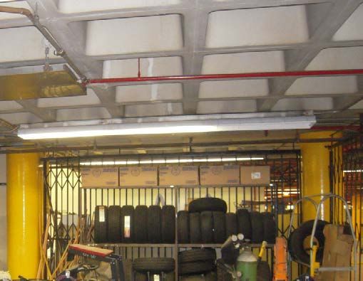
Acknowledgments
This guide provides a review of all aspects of indoor compressed natural gas vehicle maintenance facility
protection, including the initial assessment of the facility, code compliance requirements, and specific
design criteria. The authors would like to acknowledge Gladstein, Neandross & Associates in providing
considerable information and photos during the development of this handbook.

Authors
Kay Kelly and Margo Melendez, National Renewable Energy Laboratory

Co-Authors
John Gonzales and Lauren Lynch, National Renewable Energy Laboratory
Bob Coale and Jarrod Kohout, Gladstein, Neandross & Associates

Work Sponsor
The U.S. Department of Energy Vehicle Technologies Office, Clean Cities program, and Dennis A. Smith
and Mark S. Smith

Reviewers
Steve Saltzgiver, Mercury Associates, Inc.
Ted Barnes, Gas Technology Institute
Rob Adams, Marathon Technical Services, LLC
Andrew Klock and Susan Bershad, National Fire Protection Association
Stephe Yborra, Yborra & Associates, LLC

Disclaimer
This report was prepared as an account of work sponsored by an agency of the United States government.
Neither the United States government nor any agency thereof, nor any of their employees, makes any
warranty, express or implied, or assumes any legal liability or responsibility for the accuracy, completeness,
or usefulness of any information, apparatus, product, or process disclosed, or represents that its use would
not infringe privately owned rights. Reference herein to any specific commercial product, process, or
service by trade name, trademark, manufacturer, or otherwise does not necessarily constitute or imply its
endorsement, recommendation, or favoring by the United States government or any agency thereof. The
views and opinions of authors expressed herein do not necessarily state or reflect those of the United States
government or any agency thereof.

Every effort has been made to ensure that this manual is accurate, complete, and comprehensive at the time
of publication. It is intended to be used as a guide and resource document. The authors strongly encourage
all parties with an interest in establishing compressed natural gas vehicle maintenance facilities to engage
professional support to ensure code compliance and optimal systems operation.

This document is not intended for use as a “how to” guide for individuals or organizations performing
facility modifications.

II                 COMPRESSED NATURAL GAS VEHICLE MAINTENANCE FACILITY MODIFICATION HANDBOOK
Glossary

Air Changes per Hour (ACH): A measurement of the                  International Fire Code (IFC): A guidance document
number of volumetric air exchanges within a structure             commonly used with, or in lieu of, NFPA 30A that covers
caused by natural or mechanical ventilation.                      the design of vehicle maintenance facilities and protection
                                                                  systems.
Authority Having Jurisdiction (AHJ): Person(s) or agency
responsible for reviewing, approving, and permitting              International Mechanical Code (IMC): A guidance
proposed modifications, and issuing construction and              document that establishes regulations for the design and
occupancy permits. For the purposes of this document an           operation of mechanical systems based on prescriptive and
AHJ is an agency.                                                 performance-based provisions commonly used with, or in
                                                                  lieu of, NFPA 30A.
Class I, Division 1 Electrical Hazard Zone: A zone that
is expected to contain hazardous concentrations of gas or         Lower Flammability Limit (LFL): The minimum concentra-
vapor in the event of a spill or leak which, therefore, must      tion of a combustible gas that will support combustion;
be provided with ignition source protection.                      sometimes referred to as the lower explosive limit (LEL).
                                                                  This is generally accepted to be 5% natural gas in air by
Class I, Division 2 Electrical Hazard Zone: A zone which          volume at atmospheric conditions.
may contain hazardous concentrations of gas or vapor and,
therefore, must be protected. For compressed natural gas          Major Repair Garage: A maintenance facility in which
vehicle maintenance facilities, Class I, Division 2 represents    major repairs are performed, such as engine overhauls,
conditions in which methane releases could occur but are          vehicle chassis and body repairs, and similar work, that
not expected.                                                     require emptying the vehicle’s fuel tank. Any work that
                                                                  involves service to a vehicle’s fuel system also falls into this
Compressed Natural Gas (CNG): Natural gas that consists           category.
primarily of methane and small amounts of ethane, propane,
and heavier hydrocarbons and has been compressed and              Make-up Air: Fresh air that replaces air that is exhausted
stored in high-pressure vessels at pressures up to 5,000          from a structure.
pounds per square inch (psi).
                                                                  Methane (CH4): The primary component of natural gas.
Creditable Release: A release of natural gas within a repair
garage that results in a plume of sufficient concentration that   Minor Repair Garage: A maintenance facility in which
it exceeds the lower flammability limit.                          minor repairs are performed, such as lubrication, engine
                                                                  tune-ups, replacement of parts and tires, fluid changes, and
Design-Build (DB): A type of contract whereby the selected        similar maintenance work, that does not require emptying
contractor is responsible for the complete design of the          a vehicle’s fuel tank. Any work that involves service to a
facility, securing permits, procurement, construction,            vehicle’s fuel system is not permitted in a Minor Repair
commissioning, startup, and often maintenance activities.         Garage.

Design-Bid-Build (DBB): A type of contract whereby one            National Fire Protection Association (NFPA): NFPA is a
consultant is responsible for preparing the facility design       global, nonprofit organization devoted to eliminating death,
and permitting documents while a building contractor              injury, and property and economic loss due to fire, electrical
is responsible for pulling permits, procuring equipment           hazards, and related threats. NFPA’s codes and standards are
and materials, construction, commissioning, startup, and          designed to minimize the risk and effects of fire by estab-
sometimes maintenance activities.                                 lishing criteria for building, processing, design, service,
                                                                  and installation in the United States, as well as many other
Hot Work: A type of maintenance work involving the                countries. NFPA 30A is the basic document used in conjunc-
use of oxyacetylene torches and/or electric arc welders.          tion with maintenance facilities. Portions of NFPA 88A may
This could also include the use of grinders or other spark-       also apply.
producing tools.
                                                                  Natural Gas: Natural gas used as a vehicle fuel is composed
Ignition Source: A spark, flame, electricity, static              of 90%–95% methane and other longer-chain simple
electricity, or hot surface capable of igniting a                 hydrocarbons. When used in the gaseous state, natural gas
fuel that is within its combustible range.

SEPTEMBER 2017                                                                                                                  III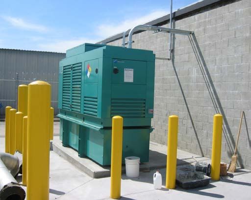
is compressed to pressures up to 5,000 psi and is commonly
known as compressed natural gas (CNG). Natural gas is odor-
ized with mercaptan to yield the familiar “rotten egg” smell.

Natural Gas Vehicle: A motor vehicle with a combustion
engine fueled by natural gas.

Paths of Migration: The flow paths by which natural gas
travels as it dissipates throughout a structure.

Pressure Relief Device (PRD): A valve activated by high
temperature or pressure used to eliminate overpressure in a
vehicle fuel tank or system. A temperature-activated valve
is designed to open at a given temperature (for example
in the event of a fire) and remain open. Once the device is
activated, the valve remains permanently open and cannot
be reset to the closed position. A pressure-activated valve
is designed to open at a given pressure and will remain
open until the overpressure is released. This type of valve
is resettable and will reseal when the lower prescribed
pressure is realized.

Pressure Release Valve (PRV): A type of valve used to
control or limit the pressure in a system or vessel. A PRV is
usually resettable and when activated by high pressure will
open to release the overpressure until a lower prescribed
pressure is realized, then reseal. PRVs are usually found
on stationary tanks and equipment and can also be used for
vehicle pressure regulators. PRVs are also known as safety
relief valves (SRVs).

Upper Flammability Limit (UFL): The maximum concen-
tration of a combustible gas that will ignite; sometimes
referred to as the upper explosive limit (UEL). This is
generally accepted to be 15% natural gas in air by volume
at atmospheric conditions.

IV               COMPRESSED NATURAL GAS VEHICLE MAINTENANCE FACILITY MODIFICATION HANDBOOK
Contents

Introduction .  .  .  .  .  .  .  .  .  .  .  .  .  .  .  .  .  .  .  .  .  .  .  .  .  .  .  .  .  .  .  .  .  .  .  .  .  .  .  .  .  .  .  .  .  .  .  .  .  . 4
Regulations .  .  .  .  .  .  .  .  .  .  .  .  .  .  .  .  .  .  .  .  .  .  .  .  .  .  .  .  .  .  .  .  .  .  .  .  .  .  .  .  .  .  .  .  .  .  .  .  .  . 6
Facility Assessment and Design Considerations  .  .  .  .  .  .  .  .  .  .  .  .  .  .  .  .  .  .  .  .  .  .  .  . 6
      Paths of Migration .  .  .  .  .  .  .  .  .  .  .  .  .  .  .  .  .  .  .  .  .  .  .  .  .  .  .  .  .  .  .  .  .  .  .  .  .  .  .  .  .  .  . 8
      Ventilation . . . . . . . . . . . . . . . . . . . . . . . . . . . . . . . . . . . . . . . . . . . . . . . . 10
      Space Heating . . . . . . . . . . . . . . . . . . . . . . . . . . . . . . . . . . . . . . . . . . . . . 15
      Electrical Wiring, Lighting, and Appliance Considerations  .  .  .  .  .  .  .  .  .  .  .  .  .  .  . 16
      Gas Detection, Alarm, and Control Systems .  .  .  .  .  .  .  .  .  .  .  .  .  .  .  .  .  .  .  .  .  .  .  .  . 19

Other Considerations  .  .  .  .  .  .  .  .  .  .  .  .  .  .  .  .  .  .  .  .  .  .  .  .  .  .  .  .  .  .  .  .  .  .  .  .  .  .  .  .  .  .  . 24
      Vehicle Fuel System Defueling  .  .  .  .  .  .  .  .  .  .  .  .  .  .  .  .  .  .  .  .  .  .  .  .  .  .  .  .  .  .  .  .  .  . 24
      Engine Exhaust Extractors  .  .  .  .  .  .  .  .  .  .  .  .  .  .  .  .  .  .  .  .  .  .  .  .  .  .  .  .  .  .  .  .  .  .  .  .  . 24
      Isolation of Non-Work Areas .  .  .  .  .  .  .  .  .  .  .  .  .  .  .  .  .  .  .  .  .  .  .  .  .  .  .  .  .  .  .  .  .  .  .  . 25
      Automatic Shut-Off of Building Gas Supply .  .  .  .  .  .  .  .  .  .  .  .  .  .  .  .  .  .  .  .  .  .  .  .  .  . 25
      Associated Bays .  .  .  .  .  .  .  .  .  .  .  .  .  .  .  .  .  .  .  .  .  .  .  .  .  .  .  .  .  .  .  .  .  .  .  .  .  .  .  .  .  .  .  . 26

Implementation .  .  .  .  .  .  .  .  .  .  .  .  .  .  .  .  .  .  .  .  .  .  .  .  .  .  .  .  .  .  .  .  .  .  .  .  .  .  .  .  .  .  .  .  .  .  . 26
Project Costs and Schedules .  .  .  .  .  .  .  .  .  .  .  .  .  .  .  .  .  .  .  .  .  .  .  .  .  .  .  .  .  .  .  .  .  .  .  .  .  . 28
      Facility Modification Costs  .  .  .  .  .  .  .  .  .  .  .  .  .  .  .  .  .  .  .  .  .  .  .  .  .  .  .  .  .  .  .  .  .  .  .  .  . 28
      Facility Modification Timelines  .  .  .  .  .  .  .  .  .  .  .  .  .  .  .  .  .  .  .  .  .  .  .  .  .  .  .  .  .  .  .  .  .  . 30

Appendix A. Specific Properties of Common Vehicle Fuels .  .  .  .  .  .  .  .  .  .  .  .  .  .  .  .  . 31
Appendix B. Preliminary Maintenance Facility Assessment  .  .  .  .  .  .  .  .  .  .  .  .  .  .  .  . 32
Appendix C. Minor/Major Maintenance Facility Assessment .  .  .  .  .  .  .  .  .  .  .  .  .  .  .  . 34

SEPTEMBER 2017                                                                                                                                                        1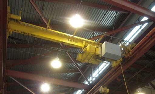
List of Figures
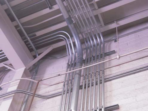
Figure 1. Unsealed conduit or pipes passing through walls or ceilings present a potential path of migration....9
Figure 2. Structural members passing through a wall present a potential path of migration............................10
Figure 3. Gaps between walls and the corrugated ceiling panels present a potential path of migration............10
Figure 4. Wall penetrations properly sealed to prevent migration .................................................................10
Figure 5. A potential path of migration created by an open passageway .......................................................10
Figure 6. Examples of stairways to upper levels that are potential paths of migration....................................10
Figure 7. A pass-through window presents a potential path of migration........................................................11
Figure 8. Roof-mounted upblast fan............................................................................................................12
Figure 9. Direct fan intake with louvers.......................................................................................................12
Figure 10. Intake ducting used to evacuate air from specific areas...............................................................12
Figure 11. Non-compliant fan has fan intake flowing over the motor..............................................................13
Figure 12. Ground-mounted fan with external ducting..................................................................................13
Figure 13. Ceiling configuration with “pockets”............................................................................................14
Figure 14. Security mesh in overhead doors................................................................................................14
Figure 15. In-wall louver that provides make-up air flow................................................................................14
Figure 16. Powered sidewall fan that provides make-up air flow....................................................................14
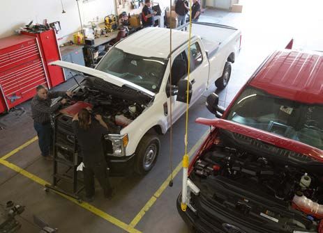
Figure 17. Conventional fuel maintenance facility ventilation pickup points....................................................15
Figure 18. Gas-fired infrared tube-type heater needs to be replaced or removed............................................16
Figure 19. Electric infrared radiant heater needs to be replaced or removed..................................................16
Figure 20. Floor-mounted portable propane heater should be eliminated.......................................................16
Figure 21. Gas-fired fan heater needs to be replaced or removed.................................................................16
Figure 22. Relocating multiple conduits, such as those shown here, would be costly and complex..................17
Figure 23. Low-voltage wiring and devices...................................................................................................17
Figure 24. Overhead lighting fixture and ballast that must be relocated.........................................................18
Figure 25. An overhead rotary fan that presents a potential ignition source...................................................18
Figure 26. A typical electric door motor.......................................................................................................18
Figure 27. A typical overhead crane............................................................................................................18
Figure 28. Typical infrared combustible gas detection head..........................................................................19
Figure 29. A ceiling-mounted combustible gas detection head......................................................................20
Figure 30. Gas detector calibration tubing...................................................................................................20
Figure 31. Examples of alarm status lights and horn panels (external and internal)........................................20
Figure 32. A combustible-gas detection system control panel.......................................................................21
Figure 33. A typical emergency generator installation...................................................................................22
Figure 34. Example of a preliminary facility layout presenting proposed equipment........................................23
Figure 35. Typical hand-held portable methane detector..............................................................................23
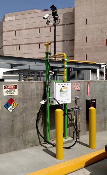
Figure 36. A defueling post........................................................................................................................24
Figure 37. A defueling station that defuels to a CNG station.........................................................................24
Figure 38. The exhaust from a natural gas engine is hotter than that from a diesel engine, so some
exhaust extractor hoses may need to be replaced during the facility modifications........................25
Figure 39. Typical mezzanine and adjacent storage areas............................................................................25
Figure 40. Representation of Clean Energy’s “Easy Bay”..............................................................................25
Figure 41. Electrically controlled main gas shut-off valve..............................................................................26
Figure B1. Critical decision path of a CNG vehicle maintenance facility modification......................................33
2 COMPRESSED NATURAL GAS VEHICLE MAINTENANCE FACILITY MODIFICATION HANDBOOK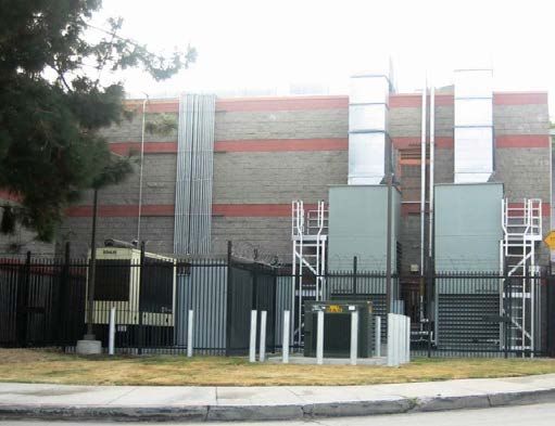
List of Tables
Table 1. Possible Series of Actions Based on the Two Suggested Levels of Detection....................................22
Table 2. CNG Vehicle Maintenance Facility Modification Schedule.................................................................31
Table A1. Specific Properties of Common Vehicle Fuels...............................................................................31

SEPTEMBER 2017                                                                                                                           3
Introduction
To ensure the safety of personnel and facilities, vehicle additional safeguards, such as combustible-gas detectors
maintenance facilities are required by law and by and control systems or specialized space heating, which
guidelines of the National Fire Protection Association are not needed in facilities servicing liquid-fuel vehicles.
(NFPA), the International Mechanical Code (IMC),
and the International Fire Code (IFC) to incorporate
certain building/structural design features. They are also Although some of the means of protection for CNG
required to be fitted with certain fire protection equip vehicle maintenance facilities are similar to those used
ment and devices because of the potential for fire or for liquid-fueled vehicles, the types and placement of
explosion if fuel leaks or spills. All fuels have an explo the equipment are different because of the gaseous
sion or fire potential if specific conditions are present;
nature of the fuel and its properties.
however, the means of ensuring safety are different based
upon the properties of different fuels.
The hazard presented by liquid fuels, such as gasoline This handbook covers the five primary elements below
and diesel, results from the spillage of these liquids and that must be considered when developing a CNG vehicle
subsequent ignition of vapors, causing a fire or explo maintenance facility design that will protect against the
sion. Facilities that maintain liquid-fueled vehicles and ignition of natural gas releases.
implement appropriate safety measures are protected
with ventilation systems designed to capture liquid fuel • Ventilation must provide sufficient air flow to reduce
vapors at or near floor level. To minimize the potential the concentration of the released gas and at the same
for ignition in the event of a spill, receptacles, electrical time evacuate the gas from the structure.
fixtures, and hot-work operations, such as welding, are
• Paths of migration must be controlled to prevent the
located outside of these areas.
released gas from entering unprotected areas of the
structure.
Facilities that maintain vehicles fueled by natural gas
require implementation of different safety measures. • Space heating must be designed in accordance with
Compressed natural gas (CNG) is composed of mostly guidelines so that open flames or hot surfaces do not
methane (CH4) with slight amounts of other hydrocar provide an ignition source.
bons. CNG is lighter than air and will therefore rise to the
ceiling of the maintenance facility and quickly dissipate • Electrical wiring and equipment must be installed in
rather than remaining at or near floor level like liquid such a manner that they do not provide sources of
fuel vapors in the event of a release. If concentrations of ignition due to sparking. The equipment itself can be
5%–15% by volume of natural gas encounter an ignition designed to be “explosion proof.”
source, the natural gas may ignite, with potentially serious • Methane detection and control systems and alarms
results. However, due to natural gas’s ability to rapidly must provide defense against dangerous concen
dissipate, this concentration is rarely seen in practice. trations of natural gas by alerting personnel and
The lower flammability limit (LFL) for CNG (5.3%) is disabling potential electrical ignition sources.
considerably higher than that for gasoline (1.4%) or for
diesel (0.6%). The specific properties of methane, as well All are accompanied by the need to establish specific
as other vehicle fuels, are given in Appendix A. protocols and training to ensure safety. Each of these is
discussed in detail in this handbook.
Facilities that maintain CNG vehicles indoors must also
be protected against fire and explosion. Although some There is inconsistent and conflicting information regard
of the means of protection for CNG vehicle mainte ing CNG vehicle maintenance facility protection require
nance facilities are similar to those used for liquid-fueled ments within the industry. The purpose of this handbook
vehicles (ventilation and elimination of ignition sources), is to provide a thorough review of all aspects of indoor
the types and placement of the protection equipment are CNG vehicle maintenance facility protection, including
different because of the gaseous nature of the fuel and its the initial assessment of the facility, code compliance
properties. CNG maintenance facilities may also require requirements, and specific design criteria. Alternative
4 COMPRESSED NATURAL GAS VEHICLE MAINTENANCE FACILITY MODIFICATION HANDBOOK
means of providing a safe maintenance environment are Receive Technical Assistance from Clean Cities
also discussed. Research into various safety methods is
The U.S. Department of Energy’s (DOE’s) Clean Cities
ongoing, which means that the codes covering facility
program advances the nation’s economic, environmental,
safety may be updated over time. Always consult with the
and energy security by supporting local actions to cut
local authority having jurisdiction (AHJ) to determine
petroleum use in transportation. At the national level,
the specific codes and editions of codes that will prevail
the program provides unbiased and objective, fuel-
for their specific project.
neutral resources and information to help transportation
One of the primary variables in evaluating and modify stakeholders evaluate options and achieve goals around
ing a maintenance facility is the intended use of that alternative fuels, advanced vehicles, and other strategies
facility. The codes and regulations offer very different to promote the use of domestic fuels in transportation. At
approaches, and it is important to understand that some the local level, nearly 100 Clean Cities coalitions leverage
requirements differ based on the type of maintenance these resources to create networks of local stakeholders
work to be performed within the facility. It should be that advance transportation projects. These coalitions are
noted that the local governing body will have the final say public-private partnerships comprising businesses, fuel
as to which code(s) will be followed, and the AHJ will providers, vehicle fleets, state and local government agen
ensure the appropriate codes are followed. Early interac cies, and community organizations that share information
tion with the AHJ is an essential part of the evaluation and resources, inform public policy, educate the public,
of facility modifications. and collaborate on transportation projects.
Although similar requirements are needed for the design Clean Cities coordinators are the primary contacts for
of new CNG vehicle maintenance facilities, this hand their coalitions and work with local fleets. They can assist
book has been prepared for use by fleet and maintenance fleet and facility maintenance managers in locating quali
facility managers who are responsible for maintaining fied facility assessors, design engineers, and construction
CNG vehicles indoors in existing facilities. It is intended firms with CNG experience.
to assist managers in evaluating physical modifications
or changes in operating protocols, but is not intended
to enable them to perform the designs themselves. Clean Cities coordinators are the primary contacts for
Rather, it should educate managers about the design
their coalitions and can assist fleet and facility
variables so that they fully understand the requirements
maintenance managers in locating qualified facility
and can ensure compliance. This document is a guide;
final designs, equipment selection, and development of assessors, design engineers, and construction firms
operating protocols should be coordinated with a profes with CNG experience.
sional engineer(s) registered/licensed in the state where
the maintenance facility is located. The engineer(s) is
responsible for preparing the drawings that will be used
Visit cleancities.energy.gov to find a local Clean Cities
for permitting and construction.
coordinator.
Implementation protocols including design, permitting,
The Clean Cities program also provides technical
and construction alternatives as well as project costs and
assistance and problem-solving through Tiger Teams,
schedules are also provided in this handbook. A ques
a group of highly skilled experts from DOE national
tionnaire and a decision tree (see Appendices B and C,
laboratories and industry. Tiger Teams can help fleets
respectively) have been included to aid the user in deter
and industry tackle difficult technical and market chal
mining the best approach for the maintenance facility.
lenges. These can include issues related to deploying
This handbook covers maintenance facilities that alternative and renewable fuels, idle-reduction measures,
service CNG-fueled vehicles. Although similar require fuel economy improvements, and emerging transportation
ments are mandated for liquefied natural gas- or technologies. For fleets that have already initiated proj
liquefied petroleum gas-fueled vehicles, these are not ects, Tiger Teams can help overcome implementation or
covered in this handbook. operational challenges of new technologies, get delayed
projects moving again, or serve as a neutral third party
to conduct an analysis and identify potential solutions.
SEPTEMBER 2017 5
Additionally, they can help address safety or operational of signing off on a design rests with the local fire depart
issues by identifying the root cause of a problem and ment, or another AHJ. Other permitting agencies such as
determining next steps. the electrical, mechanical, or structural departments will
sign off on construction elements of the design. Compli
To learn more about which projects are eligible for assis ance inspections may be conducted by all of the agencies.
tance, visit the Tiger Teams page at cleancities.energy.
gov/technical-assistance/tiger-teams/. For more informa Local governing bodies adopt specific versions of the
tion about Tiger Teams, contact John Gonzales at john. above codes, and, until newer versions are officially
gonzales@nrel.gov, or Kay Kelly at kay.kelly@nrel.gov. recognized in a local governing body, the latest editions
may not be valid for design purposes. Some local govern
ing bodies may develop requirements in addition to any
Regulations national or international code they have adopted. For
this reason, it is essential that the appropriate approved/
There are a number of codes and ordinances dealing acknowledged/adopted version of the codes and ordi
with the design and use of a CNG vehicle maintenance nances are used as the basis for design and implementa
facility. The primary documents used by AHJs are NFPA tion. Although there is generally agreement between the
30A – Code for Motor Fuel Dispensing Facilities and codes and ordinances prepared by various agencies, in a
Repair Garages, and the appropriate sections of the IFC. few cases the requirements may differ.
Other documents that may be employed include:
NFPA 30A provides specific design and operational
• International Building Code requirements based on the type of maintenance per
• International Electrical Code formed within the facility. This document separates
the type of maintenance and repair activities into two
• International Mechanical Code categories: major and minor. This distinction is critical in
determining the upgrades required to existing facilities.
• NFPA 52 – Vehicular Gaseous Fuel Systems Code
• NFPA 88A – Standard for Parking Structures
It is essential that an open dialogue be established
• National Electrical Code
with the AHJ early in the design process so that a
• National Fire Code mutually acceptable design, including appropriate
equipment and operating protocols, is developed.
• National Mechanical Code.
The codes are intended to be guidelines to help the
All of these codes provide valid and safe methods for designer and the AHJ arrive at a practical solution to
facility design, but it is the local governing body that provide a safe environment within the maintenance
makes the final decision as to which are used. facility. The authors of the codes realize there are many
varying factors, particularly the overall design of a main
tenance facility, its mission, weather conditions, and other
These codes generally contain similar (or in many cases situations which preclude a “one-size-fits-all” approach
identical) language. In addition to those listed above, to facility design. It is essential that an open dialogue be
many local governing bodies have their own additional established with the AHJ early in the design process so
codes. It is essential to recognize that all of these codes that a mutually acceptable design, including appropriate
provide valid and safe methods for facility design, but it equipment and operating protocols, is developed.
is the local governing body that makes the final decision
as to which are used, and the AHJ that ensures the
codes are met. Facility Assessment and
Approval of the permit applications that contain the
Design Considerations
designs and proposed equipment for CNG facility modifi The following section provides a practical approach to
cations is generally the responsibility of local building and evaluating an existing maintenance facility for conver
safety departments. Typically, the primary responsibility sion into a facility properly equipped to perform indoor
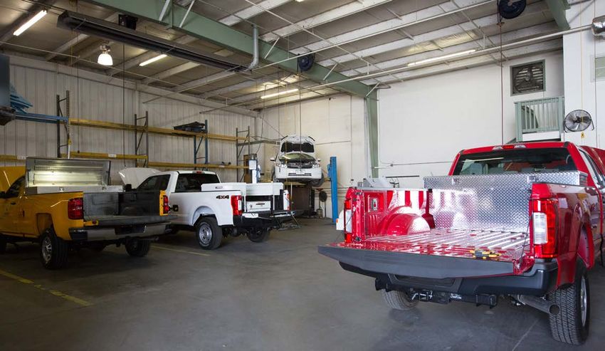
6 COMPRESSED NATURAL GAS VEHICLE MAINTENANCE FACILITY MODIFICATION HANDBOOKmaintenance on CNG vehicles. Facility assessment will
■■ Major repair garage: A maintenance facility in which
involve two steps: first, an evaluation of the fleet to be
maintained, and second, a thorough inspection of the major repairs are performed, such as engine
existing maintenance facility. The initial part of the overhauls, vehicle chassis and body repairs, and
evaluation will involve assessing the types of vehicles similar maintenance work that requires emptying the
in the fleet (including potential fleet additions) and the vehicle’s fuel tank. Any work that involves service to a
anticipated types of maintenance that will be performed vehicle fuel system may only be performed in a major
on them. The latter part of the evaluation will include a repair garage.
careful inspection of the existing structure, ventilation,
lighting, and heating and electrical systems, all of which ■■ Minor repair garage: A maintenance facility in which
may require modification or replacement. minor repairs are performed, such as lubrication,
engine tune-ups, replacement of parts and tires, fluid
Facility Needs Assessment changes, and similar maintenance work, that does
not require emptying the vehicle’s fuel tank. Any work
Essential first steps in evaluating the use of an existing
that involves service to a vehicle’s fuel system is not
facility include an analysis of the nature of the mainte
permitted in a minor repair garage.
nance that will be conducted and the types of vehicles
that will be maintained. The types of service conducted
within the maintenance facility will dictate the nature and A minor repair garage is a maintenance facility in
extent of modifications required to comply with the codes which minor repairs are performed, such as lubrication,
and ordinances. engine tune-ups, replacement of parts and tires, fluid
changes, and similar maintenance work, that does not
require emptying the vehicle’s fuel tank. Any work that
involves service to a vehicle’s fuel system is not permitted
The types of service conducted within the facility will
in a minor repair garage.
dictate the nature and extent of modifications required
to comply with codes and ordinances. It is important to note that it is the facility that is cat
egorized as major or minor, not the vehicles on which
maintenance is performed.
It is important to consider not only the present fleet
make-up, but also how the fleet may look in years to The distinctions of a major repair garage versus a minor
come. Usually a CNG fleet grows slowly as convention repair garage are critical because they define the types
ally fueled vehicles are replaced; full conversion may of protection needed within the facility and the nature
take several years. Thus, the maintenance requirements of the maintenance work that may be performed within
of today may be different in the future. the facility. The protection needed for a minor repair
garage is generally less extensive and less costly than that
required for a major repair garage because of the nature
Classification as a Major or Minor Repair Facility
of the work being performed. Fleet and facility managers
NFPA 30A and its counterparts, the IFC and the IMC, should carefully evaluate the makeup of the fleets and
are the primary codes that cover vehicle maintenance the work they expect to be performed to determine which
facilities and the classification of maintenance garages. type of garage classification best suits their operations.
NFPA 30A provides specific design and operational If ANY work classified as major is to be performed, the
requirements based on the type of maintenance per facility MUST be classified as a major repair garage,
formed within the facility. This code separates the type regardless of how infrequent or how small the activity.
of maintenance and repair activities into two categories:
major and minor. Alternative Approaches
A major repair garage is a maintenance facility in which If a fleet is small, consideration could be given to
major repairs are performed, such as engine overhauls, outsourcing vehicle maintenance to a facility suitably
vehicle chassis and body repairs, and similar maintenance authorized for indoor CNG vehicle repair. For a very
work that requires emptying the vehicle’s fuel tank. Any small fleet, all maintenance could be performed off site,
work that involves service to a vehicle fuel system may thereby eliminating the need for any maintenance facility
only be performed in a major repair garage. modifications. For these scenarios, a cost-benefit analysis
SEPTEMBER 2017 7that includes possible growth of the CNG vehicle fleet protocols. Deviation from protocols has the potential
over time will aid in determining the best option for the to create a dangerous environment as well as violate
fleet. Certain work only allowed in a major repair garage the codes and ordinances. The fleet or facility manager
(hot work or engine overhauls, for example) might be should critically review any choices being considered that
performed off site, while minor repair garage work could may cause deviations. If there is any doubt regarding
be conducted on site. This could reduce the complexity the classification of specific work activities, it is recom
and costs of facility modifications. mended that the fleet or facility manager opt for the more
stringent codes—those relating to major repair garages.
Another possibility to consider is whether or not major
garage maintenance work can be performed outdoors. Identification of Required Upgrades
In some areas, the weather is suitable to allow this
either in the open or under a canopy. However, if heavy Once a maintenance facility has been classified as either
maintenance is required, outdoor facilities may not a minor or major repair garage, an evaluation of the
have the infrastructure—overhead cranes, pits, or other existing facility should be conducted to determine what
equipment—necessary to support the work needed, or modifications will be required to achieve compliance
may not be a suitable environment due to wind, dirt, with the respective classification. The following sections
dust, and abrasive materials that may hamper the main of this handbook address the physical elements of the
tenance activities. facility that will require evaluation when assessing the
modifications necessary to maintain CNG vehicles:
If outsourcing or off-site maintenance is not cost effec
tive or practical, it is possible that certain areas within • Paths of migration
the facility can be isolated and modified to perform
• Ventilation
maintenance on CNG vehicles. This depends on the
number of maintenance bays and the layout of the • Space heating
existing facility. In some cases, bays used for the majority
of the maintenance activities (minor repairs) can be • Electrical wiring, lighting, and appliance
modified according to the requirements for minor repair considerations
garages, and separate, segregated bay(s) can be modified • Methane detection, alarm, and control systems.
according to the requirements for major repair garages.
It is not always necessary to modify an entire mainte It is essential to use a trained, experienced assessor to
nance facility to major repair garage standards if such conduct the initial inspection of the facility. Whenever
activities can be performed in a separate location that is possible, up-to-date/as-built drawings of the facility
appropriately protected. should be provided to the facility assessor. A scaled floor
plan of the entire facility is important. Other useful
It should be noted that some operational risks may be drawings include electrical plans that define the location
reduced by establishing operating protocols and training and capacity of existing switchboards, a listing of exist
programs. Such protocols may include the appropriate ing electrical equipment, and elevation drawings of the
preparation of a CNG vehicle prior to bringing it into facility. Newer facilities may have these drawings avail
the facility (e.g., checking for fuel system leaks, noting able in computer-aided design and drafting format, elec
CNG tank pressure and temperature) and ensuring that tronically stored, whereas older facilities may only have
only maintenance permitted for the garage classification paper copies of original construction drawings. In some
is conducted within the facility. cases, construction drawings may be unavailable, thereby
requiring more time and additional resources
for the facility assessor to make an assessment.
If there is any doubt regarding the classification of
specific work activities, it is recommended that the
Paths of Migration
fleet or facility manager opt for the more stringent
Natural gas used as a vehicle fuel is composed mostly
codes—those relating to major repair garages.
of methane (CH4) with small amounts of other hydro
carbons. It is lighter than air and will rapidly rise and
While every effort can be made to ensure strict adherence dissipate once released. When a natural gas release occurs
to operating protocols, human involvement presents indoors, the gas initially accumulates near the ceiling
an opportunity, deliberate or not, to deviate from such before dispersing throughout the structure and becoming
8 COMPRESSED NATURAL GAS VEHICLE MAINTENANCE FACILITY MODIFICATION HANDBOOKless concentrated. The path by which natural gas travels The inadvertent release of natural gas can occur in
as it dissipates is referred to as its “path of migration.” several ways. For example, a vehicle may have a slow
Because natural gas is normally odorless, the non-toxic leak due to an improperly sealed fuel system component.
chemical mercaptan is added to allow easy detection due Such minor releases may also occur when disconnecting
to its “rotten egg” smell. Mercaptan provides a powerful fuel system components during a repair such as a fuel
first defense in detecting a natural gas leak. The smell can filter change. In general, it is unlikely that combustible
be detected in natural gas concentrations as low as 1%, concentrations of natural gas will result from minor leaks
well below the LFL of 5%. that occur over time because the natural gas released
from these types of leaks will dissipate rather quickly.
The path by which natural gas travels as it dissipates is Though rare, a creditable release of natural gas may
referred to as its path of migration. occur if a CNG tank or fitting fails resulting in the entire
volume of the tank emptying rapidly. To prevent against
creditable releases, CNG tanks are equipped with a
The combustible range for natural gas is from 5% to 15% pressure relief device that is set to open in the event of
by volume. Gas concentrations at the center of a release excessive pressure or temperature, releasing smaller and
are typically too rich (above the 15% concentration) to more controlled volumes of natural gas and allowing the
support combustion. However, as the gas disperses, the vehicle system and tank pressure to return to a safe range.
concentration diminishes to a fuel/air ratio that is capable
of combustion. As dispersion continues, the concentra
tion decreases to where it becomes too lean (below 5%
A facility must be modified to eliminate potential ignition
concentration) and is no longer combustible. During the
initial release, it is not uncommon to have natural gas sources that may come into contact with released gas,
concentrations within the combustible range until the as well as to ensure that the air circulation exhausts gas
concentration diminishes over time. as quickly as possible.
Unlike gasoline or diesel vapors, the ignition of natural While a CNG maintenance facility is designed to safely
gas can only occur when concentration levels are within handle all types of releases, it is the “creditable” uncon
the 5%–15% range. trolled release that presents the greatest danger. Although
this type of event is extremely rare, a maintenance facility
must be designed to protect against it.
Natural gas can be ignited by a spark, flame, or very hot
surface. To eliminate the hazard of ignition, a mainte Because natural gas is lighter than air, released gas is
nance facility must be modified to eliminate potential likely to experience interruptive forces as it disperses
ignition sources that may come into contact with released throughout the structure. Paths of migration are also
gas. Additionally, a maintenance facility must be modified affected by air movement within the structure. For this
to ensure that the air circulation exhausts gas as quickly reason, a maintenance facility must be designed to
as possible to minimize the amount of time that gas con prevent released gas from entering unprotected areas as
centrations are within the combustible range. it rises and disperses. This is accomplished by installing
Figure 1. Unsealed conduit or pipes passing through walls or ceilings present a potential path of migration. Photos courtesy
of Gladstein, Neandross & Associates, NREL 44893, 44894, and 44895
SEPTEMBER 2017 9Figure 2 (left). Structural members passing through a wall present a potential path of migration.
Figure 3 (middle). Gaps between walls and the corrugated ceiling panels present a potential path of migration.
Figure 4 (right). Wall penetrations properly sealed to prevent migration. Photos courtesy of Gladstein, Neandross & Associates,
NREL 44897, 44898, and 44896
barriers, pressurizing adjacent areas, and sealing gaps in signage should also be used to ensure that the door
the structure to prevent migration into unprotected areas. is not propped open. Doors should not be fitted with
louvers or other means of ventilation that may create
Examples of potential paths of migration resulting from paths of migration.
the structural characteristics of a facility are shown in
Figures 1–3. These potential paths of migration can be Figure 7 shows a vehicle parts room adjacent to a main
eliminated by installing sealing material around the wall tenance area that is serviced with a pass-through win
penetrations and at the ceiling level, as shown in Figure 4. dow—a potential path of migration to an unprotected
area. This hazard can be eliminated by permanently
Figure 5 shows an open passage to an adjacent non- sealing the window, adopting strict operating protocols
maintenance area through which gas migration could to ensure it is only open during active use, or installing a
occur. The two areas must be isolated to prevent migra pressurizing fan in the parts room to prevent the inward
tion between the two rooms. flow of gas from the maintenance area.
Stairways accessing an upper level could accentuate the
upward gas flow (Figure 6). In these cases, the potential Ventilation
path of migration should be intercepted by isolating Ventilation of a CNG vehicle maintenance facility is one
the two levels to prevent natural gas from entering an key area of concern that is addressed by the applicable
unprotected area. One method for isolating two areas codes. Proper ventilation can be achieved by mechanical
is to install a self-closing door between them. The door means (powered fans) or by convection to provide air
must be fitted with a self-closing mechanism to keep flow. However, it is rare that convection alone can provide
it closed except when in use. Operating protocols and sufficient or predictable air flow. There are several reasons
Figure 5 (left). A potential path of migration created by an open passageway.
Figure 6 (middle, right). Examples of stairways to upper levels that are potential paths of migration. Photos courtesy of
Gladstein, Neandross & Associates, NREL 44899, 44900, 44901
10 COMPRESSED NATURAL GAS VEHICLE MAINTENANCE FACILITY MODIFICATION HANDBOOKIFC Ventilation Requirements
The IFC states that major repair garages shall be ven
tilated at a rate of one cubic foot per minute (cfm) for
every 12 cubic feet of structural space, which is equiva
lent to five air changes per hour (ACH). Note that this
calculation is based on the total volume of the structure,
not the square footage of the floor or ceiling. Further
more, the IFC provides three options for controlling
ventilation: 1) continuously, 2) continuously while the
space is occupied via interconnection with the lighting
circuit, or 3) upon demand for dilution ventilation
triggered by the gas detection system.
Figure 7. A pass-through window presents a potential The potential energy impacts of continuous operation
path of migration. Photo courtesy of Gladstein, Neandross & and tempering of the entire volume of air in a structure
Associates, NREL 44902
influences the design of many maintenance facilities,
particularly those in cold climates. For this reason, a
for ventilating a maintenance facility. Naturally, ventila maintenance facility manager may elect to use methane
tion is necessary to quickly and effectively dilute released detection as the triggering mechanism instead of con
natural gas so that the gas concentration is below the tinuous ventilation. This method incurs similar installa
combustible level. However, ventilation is also necessary tion costs but results in greatly reduced operating costs.
to direct gas to the detection and alarm systems that will Various approaches to ventilation system design and
alert occupants to safely evacuate the facility. Lastly, ven installation of methane detection systems are discussed
tilation aids in preventing the gas from accumulating near later in this section.
potential ignition sources.
NFPA 30A Ventilation Requirements
Ventilation effectiveness under NFPA 30A is also based
The IFC and NFPA differ in their calculations and control on the total volume of the structure. However, it focuses
strategies. Knowing which code requirements the local on potential electrical sources of ignition within the
governing body follows is critical to determining which area 18 inches below the ceiling. This area is classified
control strategy should be implemented. as Class I, Division 2. NFPA 30A states that electrical
devices located in this zone do not need to meet Class I,
Division 2 specification if the structure has an effective
Unfortunately, ventilation volumes and strategies are continuous ventilation rate of at least 4 ACH. If the
one area where the codes differ significantly. All agree structure does not have this continuous ventilation rate,
that natural ventilation may be allowed at the discretion existing electrical devices that do not meet the Class I,
of the AHJ. However, if the AHJ elects to require Division 2 specification must be relocated to below this
mechanical ventilation, the IFC and NFPA differ in 18-inch zone or replaced with electrical devices rated for
their calculations and control strategies. Knowing which Class I, Division 2 service.
code requirements the local governing body follows is
NFPA 30A does not specifically address operational
critical to determining which control strategy should
parameters of ventilation systems in major repair
be implemented.
garages. Generally, fire marshals and other AHJs tend
to refer to the IFC operational guidelines of 1) continu
ous operation, 2) continuous operations while occupied,
Ventilation is necessary to quickly and effectively dilute
via interlock with lighting, or 3) methane detection
released natural gas. It is also necessary to direct gas to system-triggered. If the third operational parameter is
the detection and alarm systems and prevent it from selected, then all electrical devices in the “ceiling zone”
accumulating near potential ignition sources. must be removed, relocated, or replaced with devices
rated for Class I, Division 2 applications.
SEPTEMBER 2017 11“Hybrid” Application of IFC and NFPA
Most local governing bodies will require major repair
garages to meet the most stringent requirement, which
requires the ventilation system to be sized for 5 ACH.
However, it is essential to ensure that at the 5-ACH ven
tilation rate the building design and construction do not
potentially hinder effective air changes in the ceiling zone.
Mechanical ventilation strategies should be reviewed in
advance with the AHJ to ensure that effective ventilation
is achieved in the ceiling zone.
Figure 8. Roof-mounted upblast fan. Photo courtesy of
Ventilation Strategies Gladstein, Neandross & Associates, NREL 44698
The applicable codes do not specifically address how
the ventilation is to be achieved. Most facilities rely can pull air through exhaust ductwork serving specific
on exhaust fans to move air out of the facility. In this areas of the ceiling zone as shown in Figure 10.
case, make-up air is provided via natural draft through
Most existing maintenance facilities are equipped with
openings such as doors and louvers, or by mechanical
roof-mounted fans, some of which may be rated for use
means such as make-up air units. Facilities that were not
in Class I, Division 2 areas. In some cases, existing roof-
designed with rooftop exhaust fans instead feed make-up
mounted fans can be used with minimal modifications
air into the space with interlocked electronically actu
for compliance with CNG vehicle maintenance facility
ated gravity vents in the ceiling to maintain proper air
requirements. Roof-mounted fans require certain charac
balance. The codes require that the exhaust be through
teristics to be suitable for use in a CNG vehicle mainte
the roof of the structure and that makeup air
nance facility. For example, the fan blades and shrouds
be provided from near floor level.
must be constructed from non-sparking materials
A variety of approaches are available, each with advan
tages or disadvantages based on factors such as 1) the
local governing body’s decision regarding applicable
code, 2) the design and construction of the existing facil
ity and its ability to accommodate modifications, 3) the
climate in which the facility is located (i.e., warm weather
versus cold weather and related air-tempering energy
costs), 4) ease of operation, and 5) cost.
Ventilation approaches are based on factors such as:
1. The local governing body’s decision regarding
Figure 9. Direct fan intake with louvers. Photo courtesy of
applicable code Gladstein, Neandross & Associates, NREL 44700
2. The design and construction of the existing facility and
its ability to accommodate modifications
3. The climate in which the facility is located
4. Ease of operation
5. Cost.
The most common form of facility ventilation is a roof-
mounted upblast fan that vents into the atmosphere
(Figure 8). These exhaust fans can pull air directly from Figure 10. Intake ducting used to evacuate air from
specific areas. Photo courtesy of Gladstein, Neandross &
the space via the fan inlet as shown in Figure 9, or they
Associates, NREL 44701
12 COMPRESSED NATURAL GAS VEHICLE MAINTENANCE FACILITY MODIFICATION HANDBOOKFigure 11. Non-compliant fan has fan intake flowing Figure 12. Ground-mounted fan with external ducting.
Photo courtesy of Gladstein, Neandross & Associates, NREL
over the motor. Photo courtesy of Gladstein, Neandross &
44703
Associates, NREL 44702
(i.e., plastic or aluminum) to prevent the potential for (manual operation is also possible). Another impor
igniting released gas. In addition, the electric motor that tant consideration is that if non-rated electrical
drives the fan must be explosion-proof or located where equipment is within 18 inches of the ceiling and
the fan intake or exhaust does not pass over the electric protection is provided by ventilation only (at a rate
motor. Figure 11 shows a non-compliant belt-driven of 4 ACH), the fans must be in continuous operation
fan with the fan intake flowing over the electric motor. when CNG vehicles are in the building.
Certification of compliance must be obtained from
3. For systems activated in conjunction with facility
the manufacturer, and the type of fan selected must be
lighting, the ventilation system is interlocked with
approved by the AHJ.
the lighting circuit. The applicable codes and regula
In some cases, there is not enough space to install a fan tions assume that interior lighting will always be
or the roof cannot support the additional load of a new activated whenever a maintenance facility is occu
fan. In these cases, ground-mounted fans and suitable pied. Similar to the continuous ventilation system,
external ducting (Figure 12) can be used to comply with the associated high heating costs may make this type
requirements. of system cost prohibitive in colder climates. This
option should also be implemented with care, as a
Operation and control of the ventilation system depend release could occur when the building is not occupied
on several factors. The exhaust fans and means for and the lights are not in use. Also note that the ven
providing makeup air can 1) operate continuously, 2) be tilation required consists of 100% make-up air with
controlled automatically using a gas-detection system, or no recirculation. Therefore, although this option is
3) be activated through the facility overhead and work compliant with some codes, it is not recommended.
space lighting system. A description of each method for Some designers recommend that two levels of ventila
operation and control of the ventilation system follows: tion be employed by utilizing two-speed or variable-
speed fan motors. A two-level system will provide a
1. For ventilation systems that operate continuously, lower level of ventilation (4 ACH) to reduce noise levels
the fans are constantly running. Continuously and energy consumption while the second stage will
operating ventilation systems are most commonly provide rapid dilution. The approach taken must
employed in warmer climates where ambient air does be approved by the AHJ.
not require conditioning for worker comfort. These
systems require continuous electrical power for the Facility ceiling profiles vary considerably as a result of
fans and may entail increased fan maintenance costs. structural roof members, varying ceiling heights, or other
2. For systems controlled using a combustible-gas- internal configurations. The codes do not require airflow
detection system, the fans are only activated when across every square inch of ceiling; rather, the system
the sensors detect the presence of natural gas should be designed such that the airflow eliminates
SEPTEMBER 2017 13accumulations of natural gas which may be subject to Some maintenance facilities have bay doors equipped
ignition sources. Figure 13 shows a ceiling configuration with stops that maintain a gap (typically around 12
that could accumulate concentrations of natural gas. inches), providing a permanent ventilation space between
Because the “pockets” do not contain heaters, electrical the bottom of the door and the ground when fully
wiring, or appliances, there is no ignition source and it is “closed.” If this type of configuration presents a security
not necessary to ventilate each “pocket.” concern, a mesh or a grate can be installed at the bottom
of the door as shown in Figure 14.
Figure 15. In-wall louver that provides make-up air flow.
Photo courtesy of Gladstein, Neandross & Associates, NREL
Figure 13. Ceiling configuration with “pockets.” Photo
44706
courtesy of Gladstein, Neandross & Associates, NREL 44704
In-wall louvers (Figure 15) can also be employed to
Make-up air for the ventilation system may be derived provide a portion of the makeup air flow. Generally, they
from a number of sources. In warm climates, makeup air are not able to provide the sufficient make-up air volume
may be supplied through open bay doors. In cool or flow direction to meet the codes and regulations on
climates or in hot climates where cooling is provided, a their own. Powered side wall fans (Figure 16) may also be
continuous ducted ventilation system may be employed. used to provide the requisite air flow.
In the case of ducted systems, the bay doors may be
opened by the gas detection system interlock to provide
additional makeup air flow and additional paths of
personnel egress. It is not necessary to open all of the bay
doors in a multi-bay maintenance facility, only a suf
ficient number to provide the required makeup air flow.
Figure 16. Powered sidewall fan that provides make-up
Figure 14. Security mesh in overhead doors. Photo air flow. Photo from Gladstein, Neandross & Associates, NREL
courtesy of Gladstein, Neandross & Associates, NREL 44705 44707
14 COMPRESSED NATURAL GAS VEHICLE MAINTENANCE FACILITY MODIFICATION HANDBOOKYou can also read