COMPUTER-AIDED PHASE IDENTIFICATION AND FRAME-TO-FRAME ANALYSIS OF ENDODONTIC ASYMMETRIC RECIPROCATION ROTATION: A PRELIMINARY STUDY
←
→
Page content transcription
If your browser does not render page correctly, please read the page content below
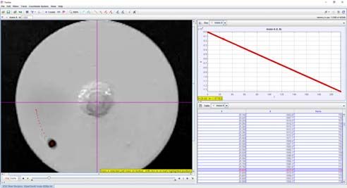
Image Anal Stereol 2020;39:91-99 doi: 105566/ias.2335
Original Research Paper
COMPUTER-AIDED PHASE IDENTIFICATION AND FRAME-TO-FRAME
ANALYSIS OF ENDODONTIC ASYMMETRIC RECIPROCATION
ROTATION: A PRELIMINARY STUDY
ALEŠ FIDLER1, EKİM ONUR ORHAN,2, ÖZGÜR IRMAK3
1
Department of Endodontics and Operative Dentistry, Faculty of Medicine, University of Ljubljana, Slovenia,
2
Department of Endodontics, Faculty of Dentistry, Eskisehir Osmangazi University, Eskişehir, Turkey,
3
Department of Restorative Dentistry, Faculty of Dentistry, Near East University, Nicosia / TRNC Mersin 10,
Turkey
e-mail: ales.fidler@mf.uni-lj.si, ekimonurorhan@gmail.com, zgrrmk@gmail.com
(Received January 28, 2020; revised April 25, 2020; accepted April 28, 2020)
ABSTRACT
To perform a detailed evaluation of reciprocating motion using a computer-aided phase identification and
frame-to-frame analysis, a continuous rotation at 300 rpm, RECIPROC ALL mode and WAVEONE
ALL-mode were recorded with a high-speed camera. Movie files were automatically analyzed with
digital video analysis and modeling tool. RECIPROC ALL mode parameters were 186.34°±1.02 at
428.32 rpm ±7.61 and 65.07°±0.93 at 261.06 rpm ± 7.72; WAVEONE ALL-mode parameters were
191.39°±1.32 at 523.83 rpm ±14.36 and 70.13°±1.26 at 316.06 rpm ± 8.75. The variability of rotational
speed during the cycle and distinct acceleration –deceleration patterns, was similar for both reciprocating
modes. The computer-aided frame-to-frame analysis revealed that asymmetrical reciprocating motion has
more complex kinematics demonstrating high peak rotational speed values and different patterns of
acceleration and deceleration. While there was a difference in reciprocating cycle duration and rotational
speed, both cycles demonstrated a similar dynamic of rotational speed during the cycle.
Keywords: frame-to-frame analysis, high speed video analysis, image analysis, kinematics, phase identi-
fication.
INTRODUCTION entirely disclosed by their manufacturers. There is limited
information about the asymmetrical reciprocating motion
Reciprocating motion increases the cyclic fatigue generated by the reciprocating motors. It has been stated
resistance of endodontic instruments, compared to that the Reciproc system generates asymmetrical 150 °
continuous rotation, independent of the endodontic counterclockwise (CCW) and 30 ° clockwise (CW) rota-
instrument- or root canal anatomy-related variables tions at 300 rpm (Kim et al., 2012), and the WaveOne
(Ferreira et al., 2017). The asymmetrical reciprocating system generates asymmetrical 170 ° CCW and 50 ° CW
motion has been recommended in root canal rotations at 350 rpm (Grande et al., 2015).
instrumentation with single-file instrumentation systems
The first study, using high-speed video analysis
(Capar and Arslan, 2016). It was based on the balanced
(Fidler, 2014), revealed that angles and angular speed
force technique (Roane et al., 1985); as an alternative to
values are significantly different from the assumed
continuous rotation tested with a non-specific clockwise-
values5,6 and these observations were further confirmed
cutting rotary file (Yared, 2008).
with subsequent studies (Irmak and Orhan 2018; Orhan et
The Reciproc (VDW GmbH, Munich, Germany) and al., 2019). It was also found that the reciprocating motion
WaveOne (Dentsply Sirona, Ballaigues, Switzerland) is more complicated compared to the continuous rotation
systems are the first representatives with their with the constant angular speed. The reciprocation motion
counterclockwise cutting single file using asymmetrical includes not only rotation phases but also standstill
reciprocating motion generated by their specific phases, needed to stop the motor and change the direction
endodontic motors. Specific preset reciprocating modes of rotation (Fidler, 2014). The visual analysis of a
for both systems have been built into these motors, and reciprocating cycle, used in previous studies (Fidler,
these preset modes could not be modified in either system. 2014; Irmak and Orhan 2018; Orhan et al., 2019). is time-
Moreover, the kinematic values for both systems are not consuming and might be prone to human observer error.
91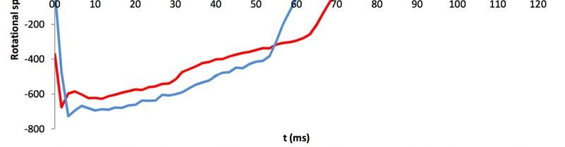
FIDLER A ET AL: Full kinematic analysis of reciprocating motion
Most importantly, it assumes the constant angular speed (Video S1 and S2). The disc was illuminated by two
during the rotational phase and therefore, does not provide light sources (Viltrox L116T LED light, Shenzhen
detailed kinematic analysis. Analysis of the reciprocating Jueying Technology Co., Ltd., Shenzhen, China). The
cycle using computer-aided methods may reduce the light outputs of each source were set at 5600K, 810lux
workload, decrease observer related bias, and provide brightness. A continuous rotation and both
more detailed analysis. reciprocating motions, RECIPROC ALL-mode (R-
mode) and WAVEONE ALL-mode (W-mode), were
This study aimed to use a computer-aided phase
captured continuously for 12s.
identification and frame-to-frame analysis for detailed
evaluation of reciprocating motion of an endodontic EVALUATION OF THE KINEMATICS
motor.
Each recorded movie file was automatically
analyzed with Tracker Video Analysis and Modelling
MATERIAL AND METHODS Tool v4.11.0. (https://physlets.org/tracker/) installed on
a personal computer (Intel i7, 16Gb RAM, 512 GB
A new torque-controlled endodontic motor (VDW
SSD + 1TB HD). The center of the polar coordinate
Silver Reciproc v1.0. SN: SR3743, VDW GmbH.) with
system, used for angle measurements, was positioned
its 6:1 contra-angle hand-piece was evaluated. Motor
in the axis of rotation, corresponding to the center of
calibration was performed before the video captures, as
the disc. The black dot was identified in the software,
recommended by the manufacturer.
and automated dot tracking was applied. The angle of
A custom disc with 40 mm diameter with a shaft rotation between the two consecutive frames was based
designed to fit into the contra-angle was manufactured on the difference the dot angulation in the polar
by a computer-numeric-control machine from coordinate system (Fig. 1). For each video, 10 s
aluminum (Irmak and Orhan 2018; Orhan et al., 2019). segments were analyzed, and two approaches were
The surface of the disc was painted with matte white utilized for evaluation of kinematic data.
paint, and a single black colored dot with a diameter of
1 mm was marked on the surface, near the edge of the AUTOMATED PHASE IDENTIFICATION
disc (Fig. 1). The black dot was used as the main ANALYSIS
reference for the image analysis. The target object An automated phase identification is based on
(disc) was inserted into the Silver Reciproc contra- visual identification of the kinematic phases (Fidler,
angle which was attached to a clamp placed in front of 2014). For continuous rotation, the duration of one
a high-speed camera (EX-F1; Casio, Tokyo, Japan). All rotation (360°) was recorded, and angular rotational
parts and surfaces were aligned using a water level. speed was calculated. For reciprocating motion, the 4
phases of each cycle, namely engaging rotation,
standstill after engaging rotation, disengaging rotation,
standstill after disengaging rotation were identified by
determination of their corresponding endpoints,
determined by the local minima and maximal angle
values (Fidler, 2014). Angle and duration of each phase
were recorded and used for calculation kinematic
parameters, defined in the previous studies (Fidler,
2014; Irmak and Orhan 2018; Orhan et al., 2019), as
follows:
Engaging angle = () (e)
Disengaging angle = () (d)
Fig. 1. Screenshot of automated frame-to-frame Engaging rotation time = ter
evaluation. On the left side is a white disc with a black Disengaging rotation time= tdr
dot, used for automatic tracking. Purple lines represent Reciprocating motion cycle duration = ter + tes + tdr
the coordinate system, positioned in the centre of + tds
rotation, small red dots represent sequential positions Engaging rotational speed = ( e / ter) x (60s /
of the black dot. 360)
The camera was adjusted to high-speed video Disengaging rotational speed (rpm) = ( d / tdr) x
mode at 600 frames per second (fps) with a resolution (60s / 360)
of 432 x 192 pixels and recorded in MOV file format Net cycle angle = () (e - d)
92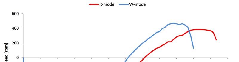
Image Anal Stereol 2020;39:91-99
AUTOMATED FRAME-TO-FRAME The rotational speed, obtained with frame-to-frame
KINEMATIC ANALYSIS analysis, demonstrates the variability of rotational
speed during the cycle for both reciprocating modes
This method is based on the calculation of frame-
(Fig. 2). The frame-to-frame rotational speed time plots
to-frame rotational speed from the angle of rotation and
of 10 averaged the R-mode, and the W-mode cycles
time interval between the two consecutive frames. The
were created (Fig. 3).
time delay between two frames was 1/600s, as
calculated from 600 FPS video recording. Data of ten
rotations and ten reciprocating cycles were acquired Table 1. Kinematic values of RECIPROCALL-mode
frame-to-frame kinematic analysis. and WAVEONEALL-mode, obtained with automated
STATISTICAL ANALYSIS phase identification analysis.
Parameter RECIPRO- WAVEONE-
Descriptive statistical analysis was performed CALL-mode ALL-mode
using MS Office Professional 2016 (Microsoft,
Sample size (n) 87 102
Redmond, USA).
Engaging angle CCW (°) 186.341.02 191.391.32
RESULTS Assumed engaging angle 150.000.00 1700.00
CCW (°)
The rotational speed of continuous rotation for
phase identification and frame-to-frame method were Disengaging angle CW 65.070.93 70.131.26
(°)
297.23 and 297.22 rpm, respectively and were similar
to the set value of 300rpm. The standard deviation of Assumed disengaging 300.00 500.00
the rotational speed for the frame-to-frame method was angle CW (°)
13.58 rpm, and it was higher compared to 1.53 rpm, Net cycle angle (°) 121.270.89 121.261.19
obtained with phase identification method.
Engaging speed (rpm) 428.327.61 523.8314.36
The reciprocating kinematic values, obtained by
phase identification analysis, are given in Table 1. The Assumed engaging speed 3000.00 3500.00
(rpm)
net cycle angle of both reciprocating modes was
approximately 121°, exceeding the assumed value only Disengaging speed (rpm) 261.067.72 316.068.75
by 1°. The actual engagement angles of R-mode and Assumed disengaging 3000.00 3500.00
W-mode exceeded the assumed values approximately speed (rpm)
by 35°and 20°, respectively. Consequently, the
difference between engagement angles of the R-mode Engaging time (ms) 72.531.29 60.931.42
and the W-mode was only 5°, compared to the assumed Disengaging time (ms) 41.571.17 37.011.23
value as 20°. The same relationship was found for
Cycle duration (ms) 114.101.10 97.941.18
disengagement angles. The average engaging rotational
speed of both reciprocating motion modes was roughly Standstill after engaging 5.100.39 4.950.79
45% higher than the assumed values, i.e., 428 versus (ms)
300 and 523 versus 350 rpm, for the R-mode and the Standstill after 0.340.68 0.360.69
W-mode, respectively (see Table 1). On the contrary, disengaging (ms)
the actual disengaging rotational speeds were
Standstill after engaging 3-4 2-4
approximately 10% lower than the assumed values.
(intervals 1/600s)
The duration of standstill phases after engaging, and
disengaging rotations were longer for the R-mode Standstill after disengaging 0-1 0-1
(intervals 1/600s)
compared to the W-mode.
(CCW, counter clockwise; CW, clockwise)
93FIDLER A ET AL: Full kinematic analysis of reciprocating motion
Fig. 2. Analysis of the R-mode reciprocating cycle kinematic. Angle vs time plot (A) and rotational speed vs time
plot (B). Beginning and end of the cycle are marked with vertical black lines. The deviation between dashed black
lines (automated phase identification method), and red lines (automated frame-to-frame method) indicated the
difference between results of phase identification and obtained from the frame-to-frame analysis.
Fig. 3. Rotational speed vs time plot of 10 averaged R-mode (red line) and W-mode (blue line) cycles obtained with
automated frame-to-frame analysis. While there is a difference in cycle duration and rotational speed, both cycles
demonstrate a similar dynamic of rotational speed during the cycle.
The analysis of continuous rotation revealed a
DISCUSSION minimal difference between the assumed and measured
value. The average rotational speed obtained by the
The novel method with frame-to-frame kinematic
automated phase identification method, based on the
analysis, applied in the present study, reveals complex
full rotation cycle, exhibited very low variability, as
rotational speed dynamics during the reciprocating
indicated by SD values of 1.53 rpm. In the present
cycle. The momentary rotational speed values were
study, the standard deviations of rotational speed
found to exceed the average rotational speed by 50%
parameter were higher compared to previous kinematic
and the assumed rotational speed by over 100%.
studies, utilizing visual evaluation (Fidler, 2014; Orhan
Moreover, the acceleration-deceleration pattern was
& Irmak, 2018; Orhan et al., 2019). The previous study
found to be inverse in engagement and disengagement
has reported the arbitrary reciprocating motion and the
phase.
non-normal distribution of kinematic parameters
among each RM, however, the authors have evaluated
94Image Anal Stereol 2020;39:91-99
the limited dataset obtained visual peak-to-peak phase identification method was presented that
analysis (Irmak & Orhan, 2018). Contrarily, the 186.34 ° CCW & 65.07° CW for the RECIPROC ALL
computer-aided frame to frame analysis method mode and 191.39 ° CCW & 70.13° CW for the
evaluated a huge number of a dataset (7200 frames data WAVEONE ALL mode with acceleration to values
per each mode) and revealed a SD of 13.58, indicating above 700 rpm in the present study. The new
a small instability of rotational speed, i.e., jitter, of computer-aided phase identification and frame-to-
about 4%. In literature, computer-assisted frame analysis are obviously more precise and detailed
measurements have been utilized in numerous than to the visual peak-to-peak analysis. Therefore,
researches related medical and paramedical field due to these findings obtained by computer-aided analysis
their advantages (Dembia et al., 2012; Robert-Inacio et could be more clinically relevant than the previous
al., 2012; Alilou & Kovalev, 2013; Alilou et al., 2014; findings using peak-to-peak visual analysis. The speed
Mapayi et al., 2016; Mabaso et al., 2018; Skwirczyński of rotation is an independent variable of the fatigue
et al., 2019). These studies have been pointed out that resistance of NiTi instruments. Regardless of the
the manual assessment of angle, speed, image analysis direction, the rotational speed above 700 rpm could
measurement has been time-consuming and the negatively affect on the cyclic fatigue life of any
inevitable errors may have been seen. instrument (Ferreira et al., 2017). Another study, using
a different brand of an endodontic motor (Irmak and
Currently, there has no external calibration device
Orhan 2018), also reported similarity between the
existed for RM endo motors. However, internal
reciprocating modes regarding engagement and
calibration specifications were installed into their RM
disengagement angles, while the net cycle angles were
devices such as SILVER.RECIPROC,
roughly 20° to 30° smaller than assumed, with values
GOLD.RECIPROC, X-Smart Plus etc. All of these
between 90° and 100°.
manufacturers recommend making calibration before
operations. However, when the activate calibration The phase identification method, whether visual or
mode of RM motor, these devices only rotate in the automatic, can only measure the average rotational
CW direction. Therefore, only the continuous rotation speed during the engagement and disengagement
at 600fps was used to calibrate for analysis. It could be phases. The lack of ability to measure momentary
concluded that the motor was capable of maintaining speed represents a considerable limitation as continued
constant rotational speed, closely matching the changing the rotation direction, inherent to
assumed value. reciprocating motion, requires persistent acceleration
and deceleration. This can only be detected by
The automated phase identification method
measuring the momentary speed during the cycle. The
revealed the high similarity between engagement and
proposed automated frame-to-frame analysis facilitates
disengagement angles, as the actual difference was 5°
such analysis, and the advantage of this method over
compared to an assumed difference of 20° (150° versus
the phase identification can be seen in angle vs. time
170° for engagement and 30° versus 50°for
plot (Fig. 2). The plot demonstrates that the rotational
disengagement). The net cycle angle was similar to as
speed is not constant throughout each phase, as it is
declared, i.e., 121.3° versus 120°for both reciprocating
assumed by phase identification method and
modes. This is in accordance with a previous
represented with a straight, inclined line during both
evaluation of the same model of an endodontic motor
rotation phases and straight horizontal line during both
regarding the angle similarity of both reciprocating
standstill phases (Fig. 2). In contrast, the frame-to-
modes and net cycle angle (Fidler, 2014). Fidler (2014)
frame method reveals a non-linear angle vs. time
has noted that the kinematics of reciprocating motion
relationship, deviating from the straight line and
was more complex than it seems as described (150°
representing a variable speed during both rotation
CCW, 30° CW at 300 rpm for RECIPROC ALL mode
phases (Fig. 2). Additionally, the transition from
and 170° CCW, 50° CW at 350 rpm for WAVEONE
disengaging to engaging is sharp, while the transition
ALL mode). The argument has been discussed with the
from engaging to disengaging is smooth.
results of 158.69° CCW at 329.05 rpm & 34.65° CW at
250.16 rpm for the RECIPROC ALL mode and of The angular speed vs time plot (Fig. 2). even
159.85° CCW at 498.69 rpm & 41.44° CW at 294.31 further illustrates the difference between both methods.
rpm for the WAVEONE ALL mode. These have been The phase identification method generates horizontal
the first original findings about reciprocating motion lines, representing the average speed during rotation
kinematics in an endodontic motor phases or zero speed during the standstill phases. The
(VDW.SILVER®RECIPROC®) (Fidler, 2014). The transitions between the phases are connected by
95FIDLER A ET AL: Full kinematic analysis of reciprocating motion
vertical lines (Fig. 2). assuming an immediate change variations in temporal rotational speed variability and
of rotation. This is impossible as it would require acceleration –deceleration patterns. It should be noted
infinite acceleration and deceleration. On the contrary, that this study analyzed the kinematics of a freely
frame-to-frame analysis demonstrates a high variation rotating target object. However, the real-time
in rotational speed during the reciprocating cycle. The kinematics of reciprocating endodontic motors should
variable inclination of the curve indicates variable also be tested under conditions that simulate clinical
acceleration and deceleration (Fig 2). usage and canal shaping.
A comparison of rotational speed dynamics While rotational speed was constant in the
between R-mode and W-mode was performed on ten continuous rotation, this was not valid for reciprocating
averaged cycles (Fig. 3). Despite the difference in cycle motion, as revealed by our results. A study
duration and average speeds, both cycles demonstrate a demonstrated that the direction of reciprocation does
similar dynamic of rotational speed during the cycle in not affect cyclic fatigue resistance, assuming that the
terms of acceleration and deceleration. A very fast ratio between the engaging and disengaging angles is
acceleration was found at the beginning of the the same (Gambarini et al., 2012). However, the CW
engaging phase, leading to a temporary rotational speed and CCW angle and angle of progression affect the
over 700 rpm, that was achieved in less than 5ms (Fig. cyclic fatigue resistance (Gambarini et al., 2012). A
3). For both modes, the peak phase rotational speed study found no difference in cyclic fatigue resistance
was approximately 50% higher than average actual between “RECIPROC ALL” and “WAVEONE ALL”
phase rotational speeds and more than 100% higher was found (Pedulla et al., 2013). One of the possible
than assumed speed. This was followed by slow reasons for lack of differences between the
deceleration leading to a stand-still phase after the reciprocating modes might be the lack of difference in
engagement phase. The disengagement phase was kinematics parameters. It seems reasonable that studies
characterized by opposite acceleration-deceleration evaluating the effect of instrument motion of their
pattern, starting with slow acceleration, achieving the longevity or efficiency would include evaluation of
maximum rotational speed at the end of the kinematics and thus precluding the “black box”
disengagement phase, followed by fast deceleration principle. The recent studies have demonstrated that
(Fig. 3). The frame-to-frame analysis also confirmed instrument kinematics is the most important factor as
higher rotational speeds and shorter cycle duration of well as its metallurgical properties for its cyclic failure
W-mode in comparison to R-mode, confirming the life (Ertugrul and Orhan 2019; Orhan and Ertuğrul
results of the phase evaluation method. 2020).
The first study, evaluating kinematics, proposed Instrument related factors of its fatigue life such as
visual phase identification method and defined phases design, taper, metallurgical properties of NiTi alloy,
and parameters for kinematics description (Fidler, and manufacturing strategies have well defined
2014). Two other studies used similar methods and also (Cheung et al., 2007). In this case, the metallurgical
confirmed the phases (Irmak and Orhan 2018; Orhan et and manufacturing strategies of the instrument
al., 2019). Typically, all of these studies evaluated a production appear to be of ultimate significance
limited number of cycles, i.e., ten cycles at 6-second (Zinelis et al., 2010; Ferreira et al., 2017). Recently,
intervals within 1 minute of video (Fidler, 2014) or 20 RECIPROC® Blue (VDW GmbH) instrument has
cycles in 10 continuous seconds (Irmak and Orhan introduced as using heat-treated Blue-wire NiTi alloy
2018; Orhan et al., 2019). In this study, each mode was (Bürklein et al., 2019). Although RECIPROC® Blue
recorded for 12 s. One of the reasons for a limited has presented better root canal preparation performance
number of evaluates is a time-consuming and fatiguing than the original RECIPROC® instruments were made
evaluation. For each cycle, between 70 and 150 images of M-wire NiTi, all VDW motors (VDW.CONNECT
have to be reviewed, aiming to identify five images, Drive®, VDW.GOLD®RECIPROC® and
depicting phase boundaries. This is followed by angle VDW.SILVER®RECIPROC®) are recommended to
measurement and recording. The proposed automated use with RECIPROC® Blue instruments at the same
video analysis method enables rapid evaluation of a specific motor settings (RECIPROC or RECIPROC
large number of cycles and recording of measurements ALL modes) for safe operation (RECIPROC® Blue
in a computer file, ready for the calculation of official). Furthermore, the novel WaveOne Gold
kinematic parameters. An additional advantage of the instruments with Gold-wire NiTi (Dentsply Sirona) has
computer-aided analysis the ability of frame-to-frame used the same kinematics with original WaveOne
analysis. As shown above, it reveals considerable instruments with M-wire NiTi in its specific
96Image Anal Stereol 2020;39:91-99
Endodontic motor (PROMARK®, DENTSPLY Sirona single motor per experimental group. There have not
Inc., Tulsa Dental, TN USA) (ProMark® Official). been any exceptions in the literature regarding the
motor quantity (Fidler, 2014; Irmak and Orhan 2018;
Regardless of RM modes (W-mode or R-mode),
Orhan et al., 2019, Pirani et al., 2017; Iacono et al.,
there have been reported that some kinematic
2019).
parameters have influenced by the clinical usage of
"the same brand RM motors" in a recent study (Irmak Fidler (2014) analyzed single Silver Reciproc v1.0
& Orhan, 2018). Moreover, both previous studies have (VDW, GmbH), very recently Iacono et al. (2019)
used the same visual peak-to-peak analysis method, for analyzed and compared the kinematics of single X-
the same RM modes, SILVER.RECIPROC(Fidler, Smart Plus (Dentsply Sirona, Balleagues, Switzerland)
2014) and X-SMART Plus (Irmak & Orhan, 2018) with single sample unit of a new generation
have shown different kinematics. Likewise, there might reciprocating motor (EVO, Cefla, Imola, Italy) and the
be also a variation between each RM handpiece and preliminary results of the study had been presented by
RM motor offering different serial numbers that may Pirani et al. (2017). Irmak & Orhan (Irmak and Orhan
have different speeds, angles, and different other 2018) used single X-Smart Plus motor (Dentsply
parameters. All motors used in continuous rotation also Sirona) per group. Orhan et al. (Orhan et al., 2019)
offer a kind of reciprocation motion: They have an analyzed single reciprocating contra-angle hand-piece
“auto-reverse” function to create more safety during (Reciproc Direct, VDW GmbH). Additional
root canal preparation. Hence, they all offer CW and comparisons with other reciprocating motors could be
CCW motions – meaning more or less a reciprocating considered in future study designs.
motion. Bürklein et al. (2019b) demonstrated huge
differences of dynamic torque values in the cutting
direction compared to the releasing direction of CONCLUSION
endodontic instruments. The dynamic torque peaks
The asymmetrical reciprocating movement was
during preparation are directly related to the changes in
evaluated using phase identification and frame-to-
the rotating directions (Bürklein et al., 2019b). Real-
frame method. The frame-to-frame analysis revealed
time dynamic torque values and axial forces during the
that asymmetrical reciprocating motion has more
preparation of straight root canals using three different
complex kinematics demonstrating high peak rotational
endodontic motors and hand preparation (Bürklein et
speed values and different patterns of acceleration and
al., 2019b). Hence, this study corroborates the present
deceleration. While there was a difference in
findings.
reciprocating cycle duration and rotational speed, both
Casio EX-F1 test device is capable to capture up to cycles demonstrated a similar dynamic of rotational
1200 FPS. Formerly, a pilot test had made at 600 FPS speed during the cycle.
with 432 x 192 pixels and 1200 FPS with 336 x 96
pixels, respectively. Although higher FPS would
increase the time resolution, the angle resolution would SUPPORTING INFORMATION
be decreased due to lower image resolution. The 600
Additional supporting information may be found in
FPS with 432 x 192 pixels video recording was found
the online version of this article:
to be the optimal mode for both time and angle
resolution. Further studies can be made with Supplementary 1. Silver Reciproc® v1.0 (VDW
sophisticated high-resolution video recorders at 1000 + GmbH) at RECIPROC ALL mode.
FPS on different motors/devices. Supplementary 2. Silver Reciproc® v1.0 (VDW
The outcomes of the study may not aid directly GmbH) at WAVEONE ALL mode.
clinical impacts. The real output details of not-
adjustable set kinematics are crucial data for
manufacturers and researchers of this field for their
ACKNOWLEDGEMENTS
research & development studies. The independent
All authors have contributed significantly to this
research data that obtained with a high-precision
research project and are in agreement with this
analyzing methodology must be available in the
manuscript. We do not have any conflict of interest to
literature. The data could be collected from randomly
declare.
selected one of the quality-controlled medical products.
In literature, the analyses of the kinematic parameters
of reciprocating motions were evaluated using only
97FIDLER A ET AL: Full kinematic analysis of reciprocating motion
REFERENCES Irmak O, Orhan EO (2018). Kinematic analysis of new
and used reciprocating endodontic motors in 2
Alilou M, Kovalev V (2013). Automated object detection different modes. Int J Artif Organs 41:17-22.
and segmentation of the histocytology images using Kim HC, Kwak SW, Cheung GS, Ko DH, Chung SM,
reshapable agents. Image Anal Stereol 32: 89-99. Lee W (2012). Cyclic fatigue and torsional resistance
Alilou M, Kovalev V, Snezhko E, Taimouri V (2014). A of two new nickel-titanium instruments used in
comprehensive framework for automatic detection of reciprocation motion: Reciproc versus WaveOne. J
pulmonary nodules in lung CT images. Image Anal Endod 38:541-
Stereol 33: 13-27. Mabaso M, Withey D, Twala B (2018). Spot detection
Bürklein S, Flüch S, Schäfer E (2019a). Shaping ability methods in fluorescence microscopy imaging: a
of reciprocating single-file systems in severely curved review. Image Anal Stereol 37: 173-90.
canals: WaveOne and Reciproc versus WaveOne Mapayi T, Tapamo J, Viriri S, Adio A (2016). Automatic
Gold and Reciproc blue. Odontology 107, 96–102. retinal vessel detection and tortuosity measurement.
Bürklein S, Stüber JP, Schäfer E (2019b). Real-time Image Anal Stereol 35: 117-35.
dynamic torque values and axial forces during Orhan EO, Irmak O, Ertuğrul IF (2019). Kinematics of a
preparation of straight root canals using three novel reciprocating endodontic handpiece. Int Endod
different endodontic motors and hand preparation. J 52: 1235-43.
International endodontic journal 52: 94–104.
Orhan EO, Ertuğrul IF (2020). Cyclic fatigue life of
Capar ID, Arslan H (2016). A review of instrumentation novel rotary compactors: A scanning electron
kinematics of engine-driven nickel-titanium microscopy evaluation. Microscopy Res & Tech 83:
instruments. Int Endod J 49:119-35. 66-71.
Cheung GS, Shen Y, Darvell BW (2007). Effect of Pedulla E, Grande NM, Plotino G, Gambarini G,
environment on low-cycle fatigue of a nickel-titanium Rapisarda E (2013). Influence of continuous or
instrument. J Endod 33, 1433–7. reciprocating motion on cyclic fatigue resistance of 4
Dembia C, Liu Y, Avedisian C (2012). Automated data different nickel-titanium rotary instruments. J Endod
analysis for consecutive images from droplet 39:258-61.
combustion experiments. Image Anal Stereol, 31: Pirani C, Iacono F, Generali L, Gatto MR, Gandolfi MG,
137-48. Prati C (2017). Impact of a modified kinematic on the
Ertuğrul IF, Orhan EO (2019). Cyclic fatigue and energy‐ fatigue life of reciprocating instruments. At: www.e-
dispersive X‐ray spectroscopy examination of the s-e.eu/ese-biennial- con-
novel ROTATE instrument. Microscopy Res & Tech gress/brussels2017/absinfo/ESE-Brussels-2017-Oral-
82:2042-8. Presentations.pdf. Accessed on July 4 2019.
Ferreira F, Adeodato C, Barbosa I, Aboud L, Scelza P, PROMARK Endodontic Motor Official
Zaccaro Scelza M (2017). Movement kinematics and https://shop.dentsplysirona.com/content/dam/master/p
cyclic fatigue of NiTi rotary instruments: a systematic roduct-procedure-brand-
review. Int Endod J 50:143-52. categories/endodontics/product-
categories/endodontic-equipment/motors-and-contra-
Fidler A (2014). Kinematics of 2 reciprocating angles/motors/promark/documents/END-DFU-
endodontic motors: the difference between actual and ProMark-Motor-EN.pdf Access date 13 April 2020.
set values. J Endod 40:990-4.
RECIPROC Blue official https://www.vdw-
Gambarini G, Rubini AG, Al Sudani D, Gergi R, Culla den-
A, De Angelis F, Di Carlo S, Pompa G, Osta N, tal.com/fileadmin/Dokumente/Sortiment/Aufbereitun
Testarelli L (2012). Influence of different angles of g/Reziproke-Aufbereitung/RECIPROC-blue/VDW-
reciprocation on the cyclic fatigue of nickel-titanium Dental-RECIPROCblue-User-Brochure-EN.pdf
endodontic instruments. J Endod 38:1408-11. Access date 13 April 2020.
Grande NM, Ahmed HM, Cohen S, Bukiet F, Plotino G Roane JB, Sabala CL, Duncanson MG Jr (1985). The
(2015). Current assessment of reciprocation in ‘balanced force’ concept for instrumentation of
endodontic preparation: a comprehensive review-part curved canals. J Endod 11:203–11.
I: Historic perspectives and current applications. J
Endod 41:1778-83. Robert-Inacio F, Oudinet G, Colonna F (2012). Ship
classification from multispectral videos. Image Anal
Iacono F, Pirani C, Arias A, de la Macorra JC, Generali Stereol 31: 121-35.
L, Gandolfi MG, Prati C (2019). Impact of a modified
motion on the fatigue life of NiTi reciprocating Skwirczyński M, Gąciarz T, Skomorowski M,
instruments: a Weibull analysis. Clin Oral Invest Wojciechowski W (2019). Automated measurement
23:3095-102.
98Image Anal Stereol 2020;39:91-99
of foot deformities: flatfoot, high arch, calcaneal Zinelis S, Eliades T, Eliades G (2010). A metallurgical
fracture. Image Anal Stereol 38: 161-72. characterization of ten endodontic Ni-Ti instruments:
assessing the clinical relevance of shape memory and
Yared G (2008). Canal preparation using only one Ni-Ti
superelastic properties of Ni-Ti endodontic instru-
rotary instrument: preliminary observations. Int
ments. Int Endod J 43, 125–34.
Endod J 41:339-44.
99You can also read