Toyota Alternator Conversion to Permanent Magnet Alternator Build Manual 1.0 - Sam Redfield
←
→
Page content transcription
If your browser does not render page correctly, please read the page content below
1

Toyota Alternator Conversion to
 Permanent Magnet Alternator
       Build Manual 1.0

          Sam Redfield
2

                              Introduction
    What follows is a build manual for converting the Toyota 22R engine
alternator into a permanent magnet alternator(PMA). Developed by Sam
Redfield, the Toyota PMA conversion was designed for economy and ease
of construction. Unmodified automotive alternators are driven by an engine
at high speed and require high revolutions-per-minute(RPM) to generate
meaningful power. The conversion of an alternator to permanent magnet
alternator (PMA) allows the alternator to generate power at much lower
RPM, making it suitable for renewable energy applications such as wind
and hydroelectric generators.
    The alternator produced for the Toyota 22R engine, manufactured by
Nippondenso, is perhaps the most common alternator in the world. In
addition to its use in Toyota engines, it is used by a number of other
automobile manufacturers in other engines. It is for this reason that it was
chosen for conversion to PMA. Easily acquired in most locations, it offers
an economical alternative to commercially available PMAʼs. For the
purposes of this manual I will refer to the alternator we build as the Toyota
Permanent Magnet Alternator(TPMA).
    Originally developed for use in the Five Gallon Bucket Hydroelectric
Generator, the TPMA can be used in a variety of applications. From wind
turbines, hydroelectric and biodiesel generators to wood gasification
systems, the TPMA can be used with any low RPM system that converts
mechanical or fuel energy into electricity.

    All motors, generators and alternators, regardless of their application
have two basic components; the rotor and the stator. The rotor is the part of
the motor that spins or rotates. The stator is the part of the motor that is
stationary. Automotive alternators also require a regulator, a set of brushes
and a rectifier.
    The modification of the Toyota alternator will involve rebuilding the rotor
entirely and rewinding the stator with new wire. An unmodified 22RE
alternator can be sourced from an automotive parts store, or used, from a
junkyard. The rotor that we will build will be fitted with neodymium rare
earth magnets. The stator will be stripped of the factory installed wire and
rewound with thinner gage wire.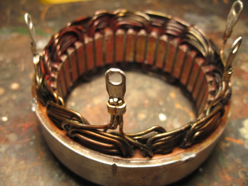
3

Contents:
Introduction.................................................................................................2

The Toyota/Nippondenso Alternator..............................................................5

The Magnets.................................................................................................6

Materials......................................................................................................6

The Rotor......................................................................................................7

The Stator.....................................................................................................7

Material Specifications...............................................................................8

Disassembly of the Toyota/Nippondenso Alternator..............................9

Removing the Back Cover............................................................................9

Removing the Voltage Regulator and Brushes from the Alternator............13

Removing the Rectifier from the Alternator.................................................15

Removing the Back of the Alternator to Reveal the Rotor and Stator.........17

Removing the Rotor from the Alternator.....................................................20

Removing the Stator from the Alternator.....................................................21

Building the Permanent Magnet Rotor...................................................21

Turning the Spindle and Bushings..............................................................22

Building the Rotor Core..............................................................................22
4

Machining the Spindle and Bushings..........................................................28

Attaching the Spindle to the Core and Bushings........................................29

Attaching the Permanent Magnets to the Core......................................30

Determine the Poles and Mark...................................................................31

Epoxying the Magnets to the Core.............................................................32

Finishing the Rotor......................................................................................35

Rebuilding the Stator ..............................................................................36

Stripping the Stator of Factory Wire ...........................................................37

Overview of the Stator Rewind ..................................................................39

Rewinding the Stator in Detail....................................................................43

Reattaching the Wire Lugs to the Stator ....................................................48

Reinstalling the Stator and Rotor ...........................................................50

Reinstalling the Stator ................................................................................50

Installing the New Rotor .............................................................................51

Reassembling the Alternator ......................................................................51

Bench Testing ............................................................................................52

Conclusion .................................................................................................53

The Toyota/Nippondenso Alternator
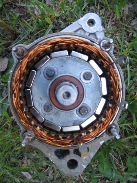
5

The Nippondenso 22RE used in this manual is a 70 amp alternator. It is
found in cars and trucks made by Toyota, Honda and other carmakers from
the mid 1980ʼs through mid 1990ʼs. When selecting the alternator to rebuild
as PMA make sure to use the 70 amp alternator. The 60 amp alternator is
identical but smaller.

(Important: The outside diameter of the 70 amp alternator for the
conversion to PMA is 125 mm.)

The front of the Nippondenso 22RE alternator.
6

The back of the Nippondenso 22RE alternator.

Later iterations(late 1990ʼs/early 2000ʼs) of the Nippondenso 70 amp
alternator will also work, as long as the spindle diameter for the rotor is 15
mm and the inside diameter of the stator is 90 mm. The length of the rotor
between the front and back bearings is 63 mm. Again, when selecting an
alternator, the outside diameter of the alternator should be 125 mm. Careful
selection of the right alternator is very important for the rebuild of the
alternator to PMA.

The Magnets:
The magnets used for the project are 1 1/2” x 3/4” x 1/4” thick nickel-plated
N42 neodymium block magnets. Twelve magnets are needed for the rotor,
but it is recommended that extra magnets be acquired as the magnets are
brittle. They are experimental magnets that are readily available from K and
J Magnetics and other experimental magnet suppliers.

Materials:

The Alternator:
Nippondenso 22RE 70 AMP alternator
7

The Rotor:
Twelve neodymium magnets
Epoxy (JB Weld or a similar metal epoxy)
Contact cement
Nuts and Bolts- Four 2” bolts with nuts, washers and lock washers.
Sheet metal
Steel
Hex Set-screws
Clear coat Enamel Engine Paint
Penetrating oil
Sharpie pen
Emery cloth
Mineral spirits or paint thinner

The Stator:
Enameled magnet wire
Nomex paper
Wood stir sticks
Motor varnish
Small wire brush
Small file
Plastic straws
Solder
Grease
Tape

Tools and Facilities:
Metal lathe
Drill press
Tin snips
Tap and die set
Wooden mallet
Hammer
Awl
Drill bits
Bench and vise
Bar clamp w/large hose clamp
8

Five-in-one screwdriver (3/8” driver, Philips and slot)
Crescent wrench
Socket set
Soldering iron
Plumbers torch
Fine metal file
Volt meter

Material Specifications:

Alternator:
Nippondenso 22RE 70 amp Circa 1986-1996
Outside diameter of alternator-125 mm
Rotor Spindle-15 mm
Stator core inside dimension-90 mm
(Later iterations of the Nippondenso 70 amp alternator will
work if the dimensions are the same)

Neodymium Magnets:
Twelve 1 1/2” x 3/4” x 1/4” thick N42 Neodymium block magnets.

Steel:
Rotor Spindle and bushings:
Steel rod-15 mm diameter x 165 mm length.
Bushings: Steel rod - 30 mm diameter x 30 mm length.
(These materials can be sourced from scrap metal)

Sheet Metal:
26 gauge, (.5 mm) for hand cut laminates. 1/3 sheet of 1200 x 2400 mm (4ʼ
x 8ʼ) to cut (76)10 cm x 10 cm squares. (Note: It is recommended that
additional laminates be made for selection of the best cut laminates.)

Nuts and Bolts:
(4)1/4” x 2” bolts, (4) 1/4” nuts, washers and lock washers

Hex Set-screws:
(4) 5 mm width x 10 mm length
9

Spindle Nut and Washers:
1/2” nut, washer and lock washer

Nomex or fish paper for stator rewind:
Type 411, .25 mm. Thirty six pieces 4 cm x 2 cm

Length of straws used for guide in stator rewind:
55 mm -Twelve one color, twelve another color.

Enameled Magnet Wire:
Essex 20.00 AWG - 10 lbs.

Wood:
Thirty six 28 mm length x 4 mm width (coffee stirrers work well)

Height of Stator Wind:
55 mm, centered. (15 mm protruding from the top and bottom of the stator
core).

Length of Phase and Wye Ends:
Stator core top to center of wire lug = 45 mm

Disassembly of the Toyota/Nippondenso Alternator:
Removing the Back Cover:
On the backside of the alternator there are three retaining nuts. Using the
five-in-one screwdriver with the screwdriver element removed, remove the
three 3/8”(9 mm) nuts that secure the sheet metal back of the alternator. If
you do not have a five-in-one screwdriver, use a 3/8ʼ or 9 mm socket
wrench. Keep the nuts(unless otherwise specified, keep all of the nuts,
screws and other components of the alternator).
10

The sheet metal back cover of the alternator is attached
with three screws.

Remove the screwdriver element from the five-in-one
screwdriver.
11

Remove the three nuts that hold the sheet metal cover of the
back of the alternator on.

With a crescent wrench, remove the nut(s) that hold the
black plastic insulator on the copper positive(+) contact on
12

the side of the alternator.

Remove the black plastic insulator from the positive (+)
copper contact.

Remove the sheet metal back cover of
the alternator.
13

Removing the Voltage Regulator and Brushes from the Alternator:
Once the back cover is removed, the rectifier, voltage regulator and brush
assembly will be exposed. The voltage regulator is the electronic
component with heat fins on top(a row of raised ridges that dissipate heat)
that terminates in the round plug interface on the back of the alternator. The
brush assembly is a pair of spring-loaded carbon contacts that contact the
rotor in the center of the alternator. Remove the three screws that hold the
voltage regulator in place. Remove the two screws that hold the brush
assembly in place. Discard the regulator, brush assembly and retaining
screws for the regulator and brush assembly.

Removing the three retaining screws for the voltage regulator.
14

Removing the two screws for the brush assembly.

Removing the voltage regulator.
15

Removing the brush assembly.

The alternator with the voltage regulator and brush
assembly removed.

Removing the Rectifier from the Alternator:
The rectifier is the last remaining electronic component on the back of the
alternator. It has four screws on the side that connect to wire lugs. These
16

lugs are attached to copper wires that enter the alternator through rubber
insulators. These four screws connect the rectifier to the stator inside the
alternator. Remove the four screws from the side of the rectifier. Pulling
upwards, gently remove the rectifier from the alternator. Remove the four
rubber insulators that surround the now exposed wires. Retain the four
rectifier screws and four rubber insulators for later use.

Removing the four screws that connect the rectifier to the
stator inside the alternator.
17

Removing the rectifier from the alternator.

Removing the four rubber insulators from the wires that
connect the rectifier to the stator.

Removing the Back of the Alternator to Reveal the Rotor and Stator:
18

Once the rectifier has been removed, use the five-in-one screwdriver to
remove the four nuts that hold on the back of the alternator. Grasp the
alternator by the back ports of the alternator. Hold the alternator aloft with
one hand. Tap the sides of the alternator with a mallet or piece of wood to
loosen the back and front of the alternator. Use the five-in-one screwdriver
to gently pry apart the front and back of the alternator. Continue tapping the
sides of the alternator and gently prying the front and back of the alternator
until the back comes off. This may take a while.

Removing the nuts that hold the front and back of the
alternator together.
19

Tapping the sides of the alternator while holding it aloft.

Prying the alternator apart with the five-in-one screwdriver.

(Note: A puller can accomplish this task with ease.)
20

Removing the back of the alternator from the front of the
alternator, revealing the rotor and stator. Remove the four
threaded studs that hold the stator in place.

Once the back of the alternator has been removed, there will be access to
four threaded studs.These threaded studs secure the stator to the front of
the alternator. Remove the four threaded studs.

Removing the Rotor from the Alternator:
Removing the rotor from the alternator can be somewhat difficult. The
pulley at the end of the rotor is often hard to get off. Find the pulley on the
front of the alternator at the end of the rotor. Using a plumbing torch, heat
the end of the rotor and the nut that holds the pulley on the rotor. While still
hot, soak the end of the rotor and pulley-retaining nut in penetrating oil.
Clamp the pulley in a bench vise. Using a socket wrench, remove the
retaining nut that holds the pulley on the rotor. Clamp the alternator in a
bench vise. Take a piece of wood or wooden mallet and tap the threaded
end of the rotor. Remove the pulley from the rotor. Continue tapping the
end of the rotor until it comes out of the alternator.

(Note: A puller can accomplish this task with ease.)
21

Removing the Stator from the Alternator:
Removing the stator from the alternator can be difficult. At this point in the
disassembly, only dirt, friction and oxidation should be holding the stator in
place. Still, it can be difficult to pull. Before you begin, use an awl to make
registration points on the stator and the alternator body at the same point
so that the stator can be reinstalled in the same location. Also, make marks
on the stator core indicating where each phase of the stator wind
terminates, and mark the common termination of the phases(these are the
copper leads that connect the stator to the rectifier.)

Apply liberal amounts of penetrating oil between the stator and the
alternator body. Holding the alternator aloft, and using gravity to assist you,
tap on the outside of the alternator with a mallet to loosen up the stator
from the alternator case. Be patient, it could take a while.

(Note: A puller can be modified to make this process much easier.)

Building the Permanent Magnet Rotor:
The permanent magnet rotor is composed of several elements: a spindle,
bushings and core. It is roughly the same dimension as a factory rotor but
rather than employing an electromagnet it is arrayed with permanent
magnets. The spindle and bushings are turned on a metal lathe. The core
is composed of twelve-sided sheet metal laminates that are glued together.
The sheet metal laminates are usually cut with tin snips and drilled out
manually. If you have access to a laser-cutter or a water-jet cutter and
CNC, this process can be made much quicker. If made by hand, the
assembled core is then bored out in the center to receive the spindle. In
addition, four holes are drilled around the center to receive the nuts and
bolts that hold the laminates together. Finally, twelve permanent magnets
are epoxied to the twelve facets of the core. You will need a metal shop to
turn the spindle and bushings of the rotor.
22

                                                !"#$%&'$()*(+,(+%-#$'./('$%&+-0#,+1(!"#$%&-

                                                                                                           !"#$%&'$()*(+,(+%-#$'./('$%&+-0#,+1(!"#$%&-
  !"#$%&'$()*(+,(+%-#$'./('$%&+-0#,+1(!"#$%&-

                                                                                               1:1 SCALE
                                                 !"#$%&'$()*(+,(+%-#$'./('$%&+-0#,+1(!"#$%&-

This schematic of the rotor is not to scale but the dimensions in inches are
correct. Considerably more laminates will be needed than pictured above if
the core laminates are cut by hand as they will be thinner material.

Turning the Spindle and bushings:
This is a job for the metal lathe.

Building the Rotor Core:
As stated above, there are a few different methods for cutting the sheet
metal laminates that make up the core. For the purposes of this manual, we
will be cutting and drilling them by hand. The total width of the completed
core is 1.5.” (38.1 mm)
When selecting the sheet metal for the laminates, it should be thin enough
to be easily cut with tin snips. The number of laminates needed to make up
the 1.5” width of the core is dependent upon the thickness of the sheet
metal used. If cut by hand, 26 gauge sheet metal should be used. The
23 sheet metal template included below shows the dimensions of the laminates. To ensure that you have the right dimension, the correct measurement between two opposing facets is 73 mm.
opposing facets is 73 mm.
                                                                                                                                                                                                                                                24

                                                                                                                                               :%*+''$#&7+,-.'+$';+(.9.+"<               %)@+   ")&+

                                                                                                                                               ".@+%'.#%'$),+$.%$.%(7+'      ",)-%
                                                                                                                                               &#*+,)%(+'<
                                                                                                                                               9,)(&.#%)*                    (7+(B+"                   &.&*+<
                                                                                                                                               )%/:*),$$)%H$
                                                                      ,+;,#":(&.#%$.%$;),&$#,$)'$)$-7#*+                                       9.%.'7
                                                                      -.&7#:&$&7+$-,.&&+%$;+,@.''.#%$#9    %+G&$)''H                 :'+"$#%                                                           !

This sheet metal template is not to scale. The distance between two
                                                                      I.%'+,&$(#@;)%H$%)@+$7+,+J$.'$
                                                                      ;,#7.F.&+">                                      );;*.()&.#%                 "#$%#&$'()*+$",)-.%/                                '()*+
25 After determining that you have the right size paper template, make a cutout of it, and accurately make a master template out of sheet metal. Use this template to trace all the remaining laminates. Use the same master template for all of the laminates. Have a sheet metal shop cut the sheet metal into appropriate sized squares, 10 cm x 10 cm, before you begin, so that the laminates are easier to work. The sheet metal blanks should be washed with soap and water to degrease them so that the contact cement will adhere to them. Precut squares for laminates. Once you have determined that you have enough laminates to make up the width of the core, coat each surface thinly with contact cement. Let the contact cement set as directed by the manufacturer before gluing the laminates together. The contact cement takes up a small amount of dimension in the overall thickness of the core. When the laminates are clamped together they will compress. Make extra laminates to make up any discrepancy in the thickness of the core. Leave the two laminates that will be on the outside of the core with one side free of contact cement.
26

A paper template is glued to a piece of sheet metal. Then
use tin snips to cut a metal template.

Laminates ready for lamination.
27

Make up 1/2” thicknesses of glued laminates and then glue these 1/2”
thicknesses together to make the total 1.5” thickness of the core.
Make sure that the laminates are lined up with each other as closely as
possible. Clamp the laminates together to squeeze out any excess contact
cement.

The laminates of the core clamped together.

Once the laminates are glued together use the paper template to make
registration marks for the four holes that receive bolts to hold the laminates
together. Use an awl to make these registration marks. With a drill press,
drill out the four holes to receive the nuts and bolts that hold the laminates
together. Drill pilot holes first and work your way up to the finish diameter of
the holes. The finish diameter of the holes should be 1/4”. Bolt the
laminates together using 2 “ long, 1/4” bolts, nuts, washers and lock
washers.
28

Cores with templates for the four side holes and center hole,
ready for drilling.

Have a machinist bore out the center hole at 15 mm to receive the spindle.

(Note: The center hole in the core is crucial to proper function of the
alternator. It is recommended that this hole be cut with a cutting tool on the
lathe and not with a drill bit, as any drift in the drill bit will be a disaster!)

Machining the Spindle and Bushings:
 The spindle should be 15 mm in diameter, 6.25” in length and threaded at
one end. The threaded end is 1.25” in length to receive a 1/2” nut. The
threaded end of the spindle should be machined square at 3/8”, 1/4“ in from
the end of the spindle. The length of the threaded and square-machined
end should be a total of 1.5”.

The thickness of the bushing on the threaded end of the spindle(the top
bushing) is 15 mm. The thickness of the bottom bushing is 10 mm. Both
bushings should be 30 mm in diameter, with a 15 mm hole in the center.
Again, a metal lathe will be needed for this process. 5 mm wide x 10 mm
long hex set-screws are tapped into the side of the bushings to link them to
the spindle.
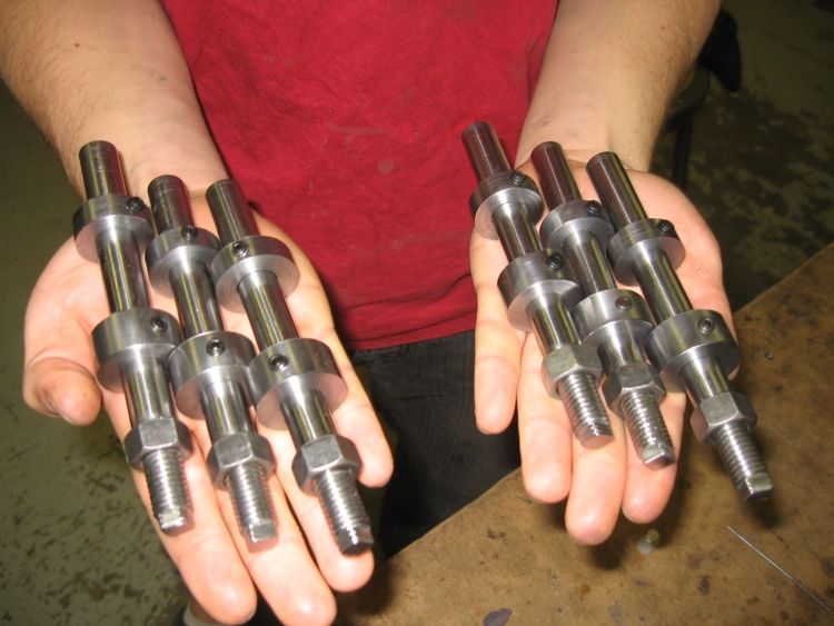
29

Rotor spindles and bushings ready for attachment to cores.

Attaching the Spindle to the Core and Bushings:
The distance from the bottom of the spindle (the non threaded end) to the
10 mm bottom bushing is 38 mm. The distance from the top of the spindle
(the threaded end) to the top bushing is 60 mm. Once you have determined
the location of the core and bushings on the spindle, tighten the hex set-
screws on the bushings to the spindle. Loosen the hex set-screws on the
bushings from the spindle and note the marks that are left in the spindle
from the hex set-screws. Using a file, file the small area on the spindle
where the hex set-screw contacts the spindle flat, so that when
reassembled, the hex set-screw wonʼt slip on the spindle. Reattach the
core and bushings to the spindle with the hex set-screws.

Once assembled, drill a 1/8” hole in the top of each bushing through the
bushing and into the core. Take two 1/8” drill bits, cut them in half and
discard the cutting ends of the bits. These will act as pins to link the rotor
core to the bushings. Put a slight bend in the non-cutting end of each of the
bits. Coat the ends of the bits in epoxy. Drive the bits through the bushings
and into the rotor core to pin the bushings to the core. Drive the pins just
30

below the flush surface of the bushings, marrying the bushings to the core
and the bushings/core to the spindle.

(note: Though this method of marrying the core and bushings to the spindle
works well, other schemes of marrying these elements such as using
compression between the core and the spindle show promise. A number of
different schemes could work here depending upon facilities.)

Attaching the Permanent Magnets to the Core:

Clamp the rotor in a vise by the core. The core now has twelve facets that
should be 1.5” in length and .75” in width. Because the laminates are cut by
hand, there is some variation in dimension. File down each facet until they
are as close as possible to the 1.5” x .75” desired dimension. Do not
exceed the 1.5” by .75” dimension.

The rotor core being filed to dimension.

(Note: This filing can be accomplished much more quickly with a sanding
machine, but extreme care should be taken not to remove too much
material from the facets of the core.)
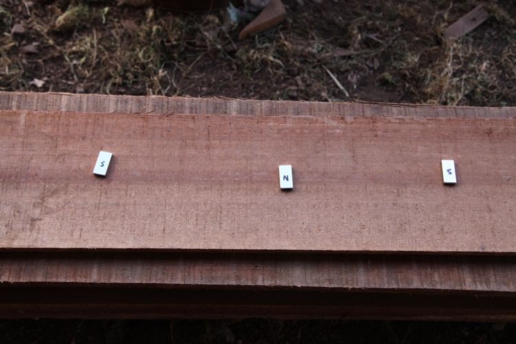
31

Now that the core and bushings are attached to the spindle it is time to
attach the neodymium magnets to the core. Special care should be taken
when handling the neodymium magnets. They are very strong magnets,
but also very brittle. Once removed from the packaging and separated, they
should be kept at least 16 inches from each other and anything magnetic.
Failure to do so may result in personal injury or damage to the magnets.
Gloves should be worn when handling the magnets, so that if you do come
in contact with anything magnetic you wonʼt get hurt.

Determine the Poles and Mark:
The magnets will be arrayed on the core with poles alternating, north/south,
north/south, etc. Once the magnets are removed from the packaging, set
them out on a bench in a row at least 16” apart. With a gloved hand, use
one of the magnets as a test magnet. Determine the poles of each magnet
by holding the test magnet to each of the magnets on the bench. Turn the
magnets over until each magnet in the row on the bench is alternately
attracted and repulsed by the magnet in your gloved hand. Double check to
make sure that you have determined that each magnet in the row is
alternately attractive and repulsive to the magnet in your hand. Use a
Sharpie pen to mark the magnets north and south.

(Note: The designation of north and south on the magnets is arbitrary. The
important thing is that the magnets alternate in polarity when arrayed on
the rotor core.)
32

The magnets are laid out with alternating poles and marked.

The back, unmarked, side of the magnets are roughed up with emery cloth
or sandpaper for better adhesion to the core.

Epoxying the Magnets to the Core:
For easier attachment of the magnets to the rotor, drill a hole in a piece of
wood to receive the end of the spindle. Clamp the wood into a vise and
place one end of the spindle in the hole in the wood.
33

Rotors ready to receive magnets.

Once the magnets are placed on the core they will want to pull toward each
other. For this reason twelve spacers should be made up to keep them
apart. Use non-magnetic wooden coffee stirrers or pieces of plastic to keep
them apart. The spacers should be 1/8” width and at least 2” long.

Make up a small batch of epoxy (JB weld or a similar metal epoxy is best).
Wearing gloves, coat a magnet on its non-marked side and coat a facet of
the rotor core with epoxy. Lower the magnet into place, being careful not to
break the magnet with the magnetic force between it and the rotor core.
Repeat this process for all twelve magnets alternating north, south, north,
south, etc.

(Note: Wear gloves during the attachment of the magnets!)
34

Magnets being applied to the rotor core.

Once all of the magnets are roughly in position, spacers are used to
separate the magnets from each other. Reposition the magnets while the
epoxy is still setting and try to make as uniform an array as possible. As the
epoxy begins to set, the spacers are removed and further small
adjustments are made. Mineral spirits or paint thinner is used to clean up
the excess epoxy on the core assembly.
35

Magnets arrayed with opposing poles on the rotor core with
spacers.

(Note: The above process should be done as quickly as possible to ensure
the integrity of the epoxy. Once the epoxy has set, do not attempt further
adjustment of the magnets.)

Finishing the Rotor:
Once the excess epoxy is cleaned from the rotor, wash the rotor with soap
and water. Mask the spindle with tape. Coat the core, magnets and
bushings with a clear coat of polyurethane or paint. Once finished, wrap the
rotor in a thick cloth and store away from metal or other magnetic material.
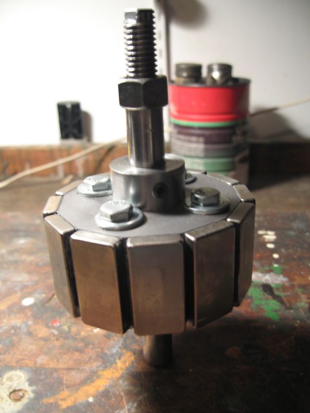
36

The finished permanent magnet rotor.

Rebuilding the Stator:
The stator is rewound with thinner gage wire than the wire that comes stock
with the alternator. Once the stock wire is stripped from the stator core, it is
rewound in the same fashion as the factory wind, but with thinner gage
wire.
37

(Note: If you are in a location where rewinding motors is readily available
and cheap(as in many developing countries), you might want to hire a
motor rewinder to perform this task as it is rather tedious and they will
probably do a better job.)

Stripping the Stator of Factory Wire:
The stator core is composed of thin sheet metal. Pay special attention to
not damaging it, as it is delicate. Take an awl and make registration points
on the core where the factory wire terminates at the wire lugs that attach to
the rectifier. Using a plumbing torch remove these lugs for use in the new
wind. Measure the length of the leads coming off of the stator once the wire
lugs have been removed. Measure the overall height of the wind, so that it
can be reproduced in the new wind and fit in the alternator. Save these
measurements for future reference.

During manufacture, the factory wire is locked into the stator core by a thick
coat of varnish. In addition, the wire itself is insulated with an enamel
coating. The wires are held in place in the stator core by wooden or plastic
inserts in the slots that hold the wire. The wire itself is insulated from the
stator core with Nomex or fish paper. The easiest way to strip the wire from
the stator is to burn off the varnish, enamel coating, and other material with
a plumbing torch. It is possible to remove the wire without a torch, but it is
much more time consuming and risks damaging the sheet metal body of
the stator.
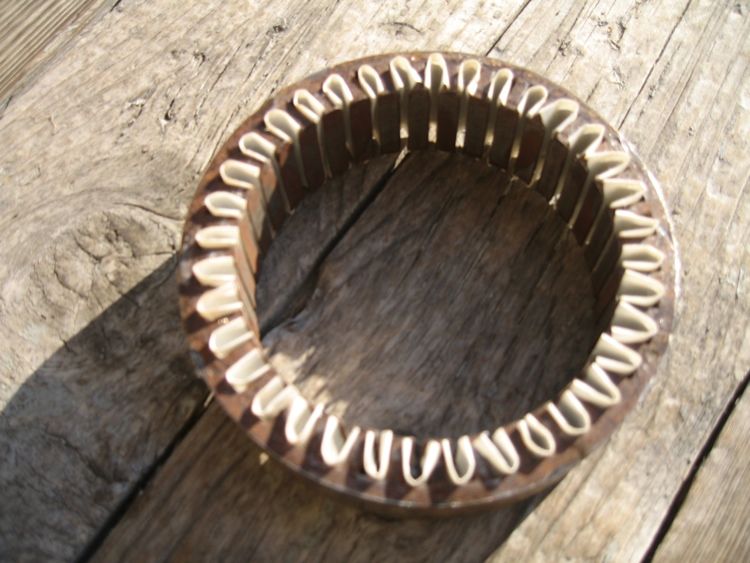
38

The stator removed from the alternator with factory wire. Note the common
wye connection in the foreground and the three phase connections in the
background.

Once the stator is stripped of factory wire, the stator core should be
cleaned.
39

Stator core stripped of factory wire.

Pay special attention to cleaning out the slots that the wire sits in, and
cleaning the outside of the stator where it fits into the alternator. This can
be accomplished with a wire brush and a small file. It is not necessary to
clean the stator core thoroughly, just remove anything that is going to get in
the way of the new wind. The process of pulling the factory wire out of the
stator may make small burrs in the stator core. File these smooth, so that
they donʼt nick the new wire and cause a short circuit in the finished stator.
40

Burs being filed from the stator.

After the stator core is stripped and cleaned, clean the inside of the front of
the alternator where the stator core fits. Confirm that the stator core will
easily slide back into position.

Overview of the Stator Rewind:

(Note: First we will give an overview of the rewind process, followed by
more in- depth instructions on page 43)

The stator wind is composed of three phases. Red, green and blue
represent the three separate phases of the wind in the graphic below.
41

The stator has three phases.

Another view of the stator rewind pattern.
42

The entire process laid out in sequence.

To keep track of the different phases of the wind, colored straws will be
placed in the slots of the stator core. These straws are used as a visual
guide to simplify the winding process; they will clearly define each of the
three phases. The length of the straws dictates the height of the loops of
the wind. The straws should be cut to 55 mm in length. Twelve of one color
straw and twelve of another colored straw.
43

Straws are used as a guide for each phase of the rewind.

As each phase of the wind is completed, the straws are removed to reveal
the next location for a phase.

The first phase has been wound and the straws for the
44

second phase have been removed to wind the second
phase.

The finished wind must fit back into the alternator. Special attention to
making the rewind the same height as the factory wind is essential. The
correct height is 55 mm.

As each phase is completed, pieces of wood are inserted into the wire slots
to keep the wire tightly in place. The finished dimension of the wood pieces
is 4 mm x 28 mm. Coffee stirrers cut down to 4 mm width work well.

Pieces of wood are installed to hold the wire in place.

Once the rewind is complete, the factory wire lugs are re-soldered to the
ends of each of the three phases, and to the common wye connection.
When re-soldering the wire lugs to the stator, make sure that they are
soldered 45 mm from the top of the stator to the center of the wire lug.

Rewinding the Stator in Detail:
Once the stator is clean of any residual varnish or other materials, Nomex
paper must be cut and folded into the cavities that receive the wire in the
stator. Accurately cut the Nomex paper to 4 cm by 2 cm lengths. Fold the
45

long ends of the Nomex back 4 mm and then fold the entire piece
lengthwise. The Nomex should snap into place in the stator cavities with
the 4 mm folded ends protruding.

The stator core slots lined with Nomex paper.

Note: Nomex is a brand name. The generic name for this material is fish
paper.

Attach the stator core to a bar clamp with a hose clamp, and clamp the
assembly to a table. Insert the colored straws, twelve one color and twelve
another color, alternating by color. These represent two of the three phases
of the wind. Leave every third slot empty.
46

The stator core hose-clamped to the end of a bar clamp
and clamped to a table. The straws are installed as a
guide.

Once the Nomex paper is installed in the slots of the stator, and the colored
straws are installed as a guide, it is time to begin winding the stator. Locate
the registration marks made earlier on the stator core for the leads of each
phase and for the common wye connection. Using 20 AWG enameled
magnet wire, wind the first phase of the stator in a serpentine pattern,
starting from the first termination point of a phase. The winds should be 55
mm high, evenly spaced on either side of the stator core. A maximum of 15
mm of wind should protrude from the top and bottom of the stator core. As
you begin the wind, make the loops shallower than the finished dimension
and work your way up to the final dimension. This will allow space for all of
the winds in each phase. When winding the phases, the enameled magnet
wire must not contact the stator core. This will cause a short circuit.
47

The first phase of the stator rewind.

(Note: The wind is shallower than the finish dimension as defined by the
straws.This will allow for all of the winds to fit.)

Allow plenty of extra slack in the end of each wind to insure that there is
enough wire to make the connections to the wire lugs. These wire lugs will
attach the stator to the rectifier when the stator is complete. It is not crucial
that each phase have exactly the same amount of winds, only that each
phase has as much wire as can fit into the slots of the stator core. As each
phase of the stator is complete, insert a piece of wood into each slot of the
phase to hold the wire in place. These pieces of wood are part of the
completed stator and should fit snugly in the stator and be trimmed to the
dimension of the stator core.
48

Wood inserts holding the first phase of the stator rewind in
place.

(Note: The magnet wire that is used for the stator has a very thin enamel
coating for electrical insulation. Be very careful not to nick this coating as it
will cause a short circuit in the finished stator and you will have to rewind it
again!)

Once each phase is complete use a volt meter or continuity tester to
determine if there is a short circuit in the phase. Sand a small amount of
insulation off the end of a phase wire. Hold one lead of the volt meter/
continuity tester to the stator core and one to the end of the sanded/
stripped phase wire. There should be no electrical connection(continuity)
between the phase and stator core. Repeat this test after each completed
phase. In addition, as each phase is completed, check to make sure that
there is no continuity between the phases.

The next step of the process is to tighten the wind to make sure that it will
clear the alternator casing. Once the three phases are complete, use an
appropriate sized jar wrapped in duct tape to the dimension of the inside of
the stator. Use a wooden mallet to gently pound the winds into a tighter
configuration. Do not exceed the inside diameter of the stator core.
49

A jar is used as a form to make a tighter wind.

Again, the stator wind must fit back into the alternator and not contact the
body of the alternator or the stator core. Test the stator core and the
individual phases against each other again for continuity. Again, there
should be no continuity between the phases and stator core or the
individual phases. Confirm that the stator will fit back into the alternator
case, and that the wind does not exceed the inside diameter of the stator
core.

When you are satisfied with the wind, and have confirmed that there are no
short circuits, it is time to coat the stator in varnish. Mask off the outside of
the stator core with tape where it will contact the alternator case. This is
necessary so that it will fit back into the alternator. Use high temperature
shellac, varnish or paint to thoroughly coat the stator and the winds.
Several coats are recommended. Use spray paint or dip the core in varnish
to penetrate the wind more deeply.

Reattaching the Wire Lugs to the Stator:
Cut the ends of the three phases and the common wye end to the
appropriate length to reach the rectifier. The distance from the top of the
stator core to the center of the wire lug is 45 mm. Double check your
measurements. Leave a little slack to ensure that you have enough wire to
50

reach the rectifier. Strip away a small portion of the enamel insulation from
the ends of each phase. Group the common ends of the three phases
together, and solder the wire lugs onto the ends of each phase and the
common wye end.

Make sure that the wire ends are long enough to receive
the wire lugs and reach the stator.
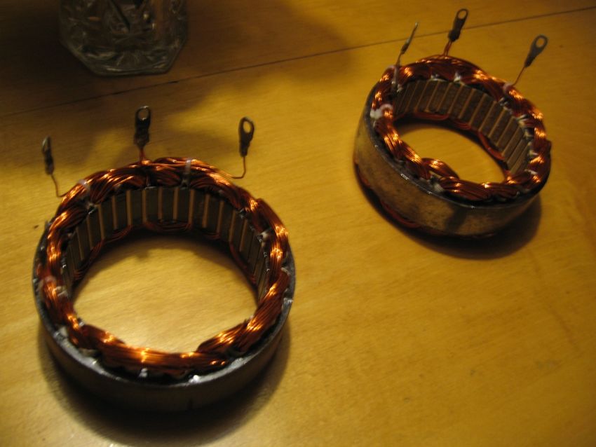
51

Finished stators with wire lugs reattached to each phase
and the common wye connection.

Check again for continuity between each phase and the common end of
each phase. Make sure there is no continuity between the common ends of
each phase and the stator core. There will now be continuity between the
three phases, because they have been joined at the wye(common) wire.
Again, there should be no continuity between the phases and the stator
core.

Reinstalling the Stator and Rotor:
Reinstalling the Stator:
52

Reinstalling the stator core into the alternator should be fairly easy. Before
beginning, confirm that the stator is in the right position to connect to the
rectifier by loosely inserting the stator into the front of the alternator. Gently
place the back of the alternator over the stator and confirm that the holes in
the back of the alternator match up with the wires and wire lugs that come
from the stator. Make a mark to identify where the stator fits into the
alternator, so that the wire lugs will meet the rectifier. Remove the stator
from the alternator.

The stator may be hard to remove once it is fully installed. Make sure that
the stator is in position for the wire lugs to meet the rectifier. Use a small
amount of machine oil if necessary on the outside of the stator core to
assist in the reinstallation. Install the stator evenly in the alternator so that it
doesnʼt bind on one side or the other. Once the stator is in place, use the
four threaded studs that were removed earlier to lock it in position.

Installing the New Rotor:
The rotor is strongly magnetic. Special care should be given to handling it
when installing it into the alternator, as the stator is magnetic. To protect the
rotor and the stator from each other, line the inside of the stator with thin
cardboard or thick paper, leaving enough slack in the material to pull it out
once the rotor is installed. The lugs are magnetic and could be pulled into
the alternator during the rotor installation. Gently bend the wire lug-ends of
each phase, and the common wye end of the phases away from the center
of the alternator. Use tape to hold them out of the way.

Clamp the alternator in a vise. The magnetic rotor will pull into the
alternator very strongly once it is close to position. Use thick gloves and
keep your fingers clear of the area between the rotor and the stator.
Approach the alternator with the threaded rotor end first, holding the rotor
from the non-threaded end of the spindle. Center the rotor as closely as
possible in the alternator. Magnetism will pull the rotor into position once
the rotor is partially inserted. Watch your fingers. Once the rotor is in
position, reinstall the pulley on the threaded end and tighten down the
pulley with a 1/2” nut, washer and lock washer. Remove the protective
paper material from between the rotor and stator and bend the wire lugs
from the stator back into position.
53

Reassembling the Alternator:
Reattach the back of the alternator to the front of the alternator using a
wooden mallet. Gently tap the back of the alternator onto the end of the
rotor spindle and into position to fit on the front of the alternator. Confirm
that the rotor turns in the alternator. The rebuilt alternator will cog when it
turns. Reinstall the rubber wire insulators that protect the phase and wye
ends of the stator from the alternator back. Tighten the back of the
alternator onto the front, using the nuts removed earlier from the threaded
studs. Reinstall the rectifier onto the back of the alternator and attach the
wire lugs to the rectifier with the screws removed earlier. The voltage
regulator and brush assembly are not reinstalled in the alternator: the
regulator is no longer useful as it is designed for higher RPM, and the
brush assembly is no longer needed as the alternator is now a brushless
permanent magnet alternator. Place the sheet metal cover for the back of
the alternator onto the alternator and reinstall the black plastic insulator
onto the positive end of the rectifier with the nut(s) removed earlier.
Reinstall the three nuts that hold the sheet metal cover of the back of the
alternator in place.

(Note: The 1” long, 1/2” threaded end of the rotor allows for enough space
for the pulley to act as a spacer to clear the outside of the alternator and
allow attachment of a turbine or other drive element in addition to the
pulley. The pulley can be used as intended, or another drive element can
be threaded onto the end.)

Bench Testing:
Clamp the alternator in a vise. Using a volt meter set to DC, attach the
positive end of the tester to the positive end of the rectifier(the threaded
copper end of the rectifier with the black plastic insulator that protrudes
from the side of the alternator). Touch the negative end of the tester to one
of the screw ends that protrudes from the sheet metal back of the
alternator. Use a piece of rope to turn the pulley on the front of the
alternator. Again, the alternator will cog as it turns. The volt meter should
register current being produced immediately. 12 volts should be produced
easily with a quick turn of the alternator. Turn the pulley faster and more
current is produced. If the alternator is difficult to turn, and produces no
current, there is either is a short circuit in the stator, or there is a burned out
54

diode in the rectifier. To trouble shoot any problems, check for continuity in
the stator as described in the stator rewind section, and check each diode
in the rectifier for continuity. If the rectifier is bad, a new or used one should
be readily available at an auto parts store or junkyard.

Conclusion:
This manual represents a first effort at detailing the construction of the
Toyota permanent magnet alternator(TPMA). The TPMA has survived well
in the field for extended periods, but improvements will no doubt be made
in the manufacture and design of the alternator. For now, the above manual
details a starting point for further iterations of the TPMA.

Further information or questions about this manual can be directed to Sam
Redfield at: samuelredfield@gmail.com       Copyright 2013 Sam Redfield
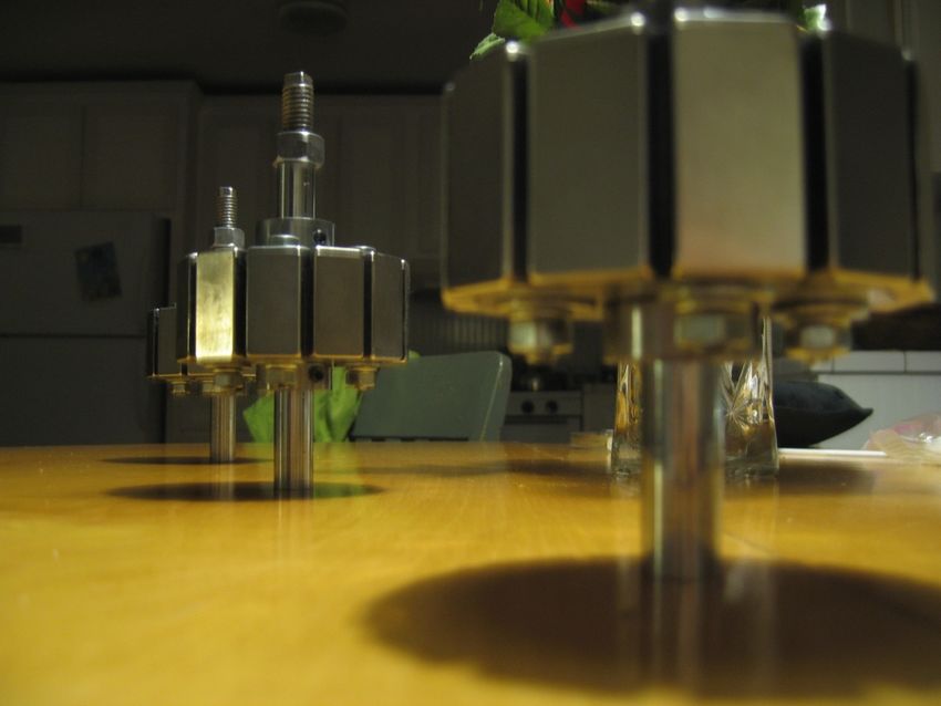
55

Permanent magnet rotors.
You can also read