Seismic radiation analyses in anisotropic media based on general dislocation source model
←
→
Page content transcription
If your browser does not render page correctly, please read the page content below
Journal of Geophysics and Engineering
Journal of Geophysics and Engineering (2021) 18, 231–240 doi:10.1093/jge/gxab006

Seismic radiation analyses in anisotropic media
based on general dislocation source model
Yi Yao1,2,3 and Yibo Wang1,2,*
1
 Key Laboratory of Petroleum Resource Research, Institute of Geology and Geophysics,
Chinese Academy of Sciences, Beijing 100029, China

 Downloaded from https://academic.oup.com/jge/article/18/2/231/6212761 by guest on 15 July 2021
2
 Institutions of Earth Science, Chinese Academy of Sciences, Beijing 100029, China
3
 University of Chinese Academy of Sciences, Beijing 100049, China
*
 Corresponding author: Yibo Wang. E-mail: wangyibo@mail.iggcas.ac.cn

Received 18 September 2020, revised 18 January 2021
Accepted for publication 29 January 2021

Abstract
Anisotropy affects the focal mechanism and makes it complicated. A shear motion generates a
pure double-couple (DC) source in isotropic media. While in anisotropic media, it will produce
non-DC components, which contain isotropic (ISO) and compensated linear vector dipole
(CLVD) components. Besides, coupled with the diversity of fault motion, the source may
become extremely complicated. In this paper, the seismic moment tensor is obtained based on
the dislocation model, and then a variety of analyses are performed with the moment tensor,
including moment tensor decomposition, radiation pattern, radiated energy ratio and seismic
propagation characteristics. Since the anisotropy of the medium also influences seismic wave
propagation, a hypothesis is made that the source region is minimal and anisotropic, but the
propagation path is isotropic. The research gives some interesting conclusions. It is found that the
anisotropy mainly affects the focal mechanism under low slope angle while high slope angle has
little effect on the polarity. In terms of the moment tensor decomposition, if only one of ISO or
CLVD exists, it can be asserted that the source region is anisotropic because ISO components are
accompanied by CLVD components in isotropy media. As for the DC component, the results
indicate it is one of the most important factors for determining the ratio of radiant energy. This
paper presents some valuable findings of the focal mechanism of the general dislocation source
under anisotropy, which helps to recognise the source characteristics of the earthquake and build
solid foundations for the subsequent inversion of the focal mechanism.
Keywords: anisotropy, moment tensor, radiation, wave propagation

1. Introduction ing amount of seismic data and mature knowledge of earth-
 quake source process, seismologists have realised that the
In the early stage of microseismic source mechanism re-
 tensile components may exist in seismic sources (Frohlich
search, many studies used shear faults to describe its fo-
 1994). Foulger et al. (2004) analysed the data recorded with
cal mechanism and this might be attributed to data noise,
 portable seismic recorders and obtained the focal mecha-
an inaccurate velocity model and computational error of al-
 nism by the P and S wave polarity and amplitude ratio in-
gorithms (Dufumier & Rivera 1997; Pesicek et al. 2012).
 version. The results show that the source type is a com-
Eisner et al. (2010) used a star surface array to calculate the
 bination of shear and tensile fracture. Šílený et al. (2009)
moment tensor and explained that the non-DC component is
 studied the hydraulic fracturing microseismicity in the Cot-
induced by inaccurate modelling. However, with an increas-
 ton Valley and found that the source mechanism of high

© The Author(s) 2021. Published by Oxford University Press on behalf of the Sinopec Geophysical Research Institute. This is an Open Access article distributed under the terms of 231
the Creative Commons Attribution License (http://creativecommons.org/licenses/by/4.0/), which permits unrestricted reuse, distribution, and reproduction in any medium,
provided the original work is properly cited.
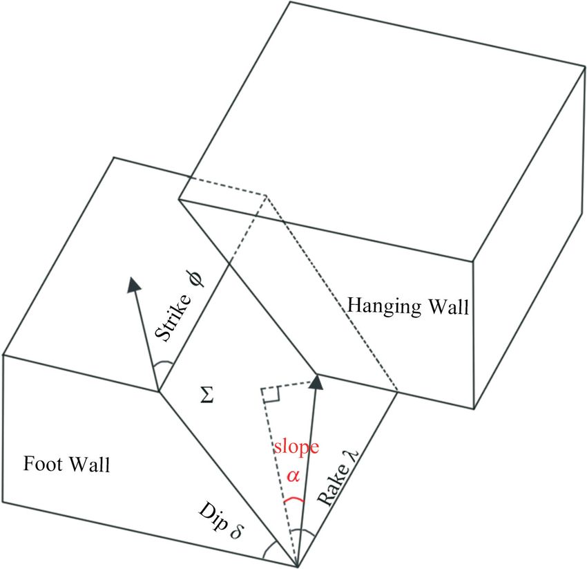
Journal of Geophysics and Engineering (2021) 18, 231–240 Yao and Wang

signal-to-noise events containing a significant non-DC com- extent, by the S/P wave amplitude ratio of the microseismic
ponent. They suggested that these microseismic events event.
are caused by high-pressure fluid injection (Rao & Wang Even though one can recognise that focal mechanisms are
2020). Staněk & Eisner (2013) similarly computed the influenced by fault motion and the properties of the area
moment tensor and investigated some non-shear compo- where the sources are located, the characteristic of seismic
nents. Pesicek et al. (2016) studied high-quality microseis- data controlled by both factors are rarely discussed. In this pa-
mic events recorded by a dense array at the surface in Mont- per, we will study the focal mechanism based on the general
ney, Canada, and used intensive seismic data to confirm the dislocation model and analyse the radiation patterns, energy
inclusion of the non-double-couple mechanism in microseis- ratio of Es /Ep and the seismic signal affected by fault motion
mic caused by hydraulic fracturing. and anisotropy.
 Vavryčuk (2001) made a mathematical analysis of the fo-
cal mechanisms, explaining why shear slip also produces non-
 2. Theory
double force components. He proposed the general dislo-
cation model, which can adequately describe an earthquake 2.1. The general dislocation model

 Downloaded from https://academic.oup.com/jge/article/18/2/231/6212761 by guest on 15 July 2021
source and predict whether the non-DC components exist
 For a general dislocation source, dislocation vector u can de-
or not. Compared with the original shear dislocation model,
 viate from the fault plane. It contains four parameters: strike
the concept of slope angle is introduced, and thus the slip
 ∅, dip , rake , and slope (Vavryčuk 2011). The former
vector is not limited to the fault plane. The faulting may
 three parameters define the faulting style, while the slope de-
comprise the shear and tensile components simultaneously,
 termines the deviation of the dislocation vector from the fault
which means the fault can be opened and closed. Song et al.
 plane. Figure 1 shows a model of a tensile earthquake. The
(2014) applied the moment theory of general dislocation to
 pure shear source happens when = 0◦ , and the pure exten-
study the microseismic source mechanisms in the Barnett
 sive source is defined by = 90◦ . In the case of = −90◦ ,
Shale region of the USA.
 this is the pure compressive source.
 However, the slope angle is not the only factor causing ten-
 The moment tensor M can be calculated by (Aki &
sile motion. In fact, the source moment tensor is a compos-
 Richards 2002)
ite result of the source tensor and medium parameters, and
the anisotropy of the source region makes the source more Mij = uScijkl vk nl , (1)
complicated. Kawasaki & Tanimoto (1981) explained that a
 where cijkl are elastic parameters surrounding the source fault,
shear slip in anisotropic media produces a non-DC source,
 u is slip displacement, S is the fault area, v is slip direction
which cannot be observed in an isotropic solid. Vavryčuk
 and n is the fault normal. Vavryčuk (2005) introduced source
(2005) presented a detailed mathematical theory proving
that anisotropy in the source region also affects the focal
mechanism. Cai et al. (2011) assumed the fault zone as
anisotropic ATI (transversely isotropic media with arbitrary
orientation axis of symmetry) media and analysed that shear
faulting can also generate isotropic components.
 The complexity of source draws the attention of seismol-
ogists to research into the focal mechanism, including radi-
ation pattern, seismic record and other relevant problems.
Related studies have been in place for many years, helping
to get a rough judgment from earthquake data. Shi & Ben-
Zion (2009) considered pure shear and pure tension sources
separately and analysed the seismic wave propagation char-
acteristics of two sources under different media conditions.
Walter & Brune (1993) established a source spectrum model
of the tensile fracture zone and compared it with the shear-
type seismic far zone model. It was found that the ampli-
tude of the P/S wave of the tensile sources was higher than
that of shear motion (Ben-Zion & Ampuero 2009; Fischer
& Guest 2011; Castro & Ben-Zion 2013). Studies by Eaton Figure 1. (a) Diagram of the general dislocation source model. , and
 are a fault’s strike, dip and rake angle, respectively. (b) Σ is the fault plane; n
& Forouhideh (2011) have shown that about 90% of shear-
 is the normal to the fault plane and v is the slip vector. is the slope angle,
type events have an S/P wave amplitude ratio greater than and the pure shear source is introduced when = 0° , while the pure tensile
five. This reveals the source type can be determined, to some source is defined by = 90° .

 232
Journal of Geophysics and Engineering (2021) 18, 231–240 Yao and Wang

tensor D and proposed the following expression: defined in equation (6):
 √ √
 Mij = cijkl Dkl , (2) Vp0 = C33 ∕ Vs0 = C66 ∕ , (6)

Here tensor D is a symmetric dyadic tensor defined as C11 − C33 C66 − C44
 = =
 uS 2C33 2C44
 Dkl = (v n + vl nkl ) . (3)
 2 k l (C13 + C44 )2 − (C33 − C44 )2
 = , (7)
 Equation (2) illustrates the relationship between the mo- 2C33 (C33 − C44 )
ment tensor and the source tensor, where C is the elastic pa- where Vp0 and Vs0 characterise the phase velocities of the P
rameter matrix with a size of 6 × 6. Therefore, equation (2) and S waves along the symmetry axis of the TI medium and
yields , and are three dimensionless factors that represent the
 anisotropy intensity.
 ⎡M11 ⎤ ⎡C11 C12 C13 C14 C15 C16 ⎤ ⎡D11 ⎤ Now we acquire the modulus of the three typical
 ⎢ ⎥ ⎢ ⎥ ⎢ ⎥

 Downloaded from https://academic.oup.com/jge/article/18/2/231/6212761 by guest on 15 July 2021
 ⎢M22 ⎥ ⎢C12 C22 C23 C24 C25 C26 ⎥ ⎢D22 ⎥ anisotropic media and substitute it into equation (4) to ob-
 ⎢M ⎥ ⎢ C C23 C33 C34 C35 C36 ⎥ ⎢D33 ⎥ tain the moment tensor in anisotropy. Before modelling,
 ⎢ 33 ⎥ = ⎢ 13 ⎥ ⋅ ⎢ ⎥. (4) we should pay attention to two crucial points. First, the
 ⎢M23 ⎥ ⎢C14 C24 C34 C44 C45 C46 ⎥ ⎢D23 ⎥
 ⎢ ⎥ ⎢ ⎥ ⎢ ⎥ influence of anisotropy on the focal mechanism is consid-
 ⎢M13 ⎥ ⎢C15 C25 C35 C45 C55 C56 ⎥ ⎢D13 ⎥ ered in our study, and how it affects source mechanisms
 ⎢M ⎥ ⎢ C C26 C36 C46 C56 C66 ⎥⎦ ⎢⎣D12 ⎥⎦ is the object of our research. Therefore, we assume that
 ⎣ 12 ⎦ ⎣ 16
 the micro-area surrounded by the source is anisotropic but
 the propagation path is isotropic, and the area is so small
2.2. Moment tensor in anisotropic media that we can take it as a point compared with the dis-
 tance between sources to the receiver. This is to facilitate
Due to the diversity of anisotropy, focal mechanism has a the comparison between isotropy and anisotropy. Second,
more general form. Thus, the radiation pattern and seismic we all know from equation (2) that two primary factors
wave propagation show various characteristics (Gao et al. are influencing the source mechanisms. One is the source
2018; Gao & Wang 2020). In seismic prospecting, transverse tensor and the other is the stiffness matrix. Therefore,
isotropy (TI) is the most common type of medium. TI is we divide these factors into three parts: faulting style (in-
a medium with an axis of symmetry, which is referred to cluding strike, slip and rake), slope angle and anisotropy
as the vertical transverse isotropy (VTI) and the horizontal represented by Thomsen parameters. Due to the vast num-
transverse isotropy (HTI), depending on whether the axis is ber of variables, we choose the slope angle as a sin-
spatially oriented vertically or horizontally. Tilted transverse gle variable, and the others as control variables, which
isotropy (TTI) is formed from VTI when an inclination an- means the media parameter or faulting style keeps con-
gle (also called the polarisation angle) occurs between the stant d and the effect of the slope angle is observed
axis of symmetry and the vertical axis. When equals 90°, it on the numerical experiments. Therefore, in our mod-
becomes the HTI medium. elling, we will consider four types of medium, includ-
 The stiffness matrix of the TI medium has five indepen- ing isotropic media (IM), VTI, TTI and HTI, whose
dent elastic parameters, and matrix C in the VTI medium is parameters are shown in Table 1. However, it is noted
expressed as: that under particular faulting geometry and some individ-
 ual anisotropy with higher symmetry, the moment tensor
 ⎡ C11 C11 − 2C66 C13 0 0 0 ⎤ has only the DC components (Vavryčuk 2005). To avoid
 ⎢ ⎥
 ⎢C11 − 2C66 C11 C13 0 0 0 ⎥ these phenomena, we will set the three parameters of fault-
 ⎢ C C13 C33 0 0 0 ⎥ ing styles as a random but not typical value (listed in
 C=⎢ ⎥.
 13
 (5) Table 2).
 ⎢ 0 0 0 C44 0 0 ⎥
 ⎢ ⎥
 ⎢ 0 0 0 0 C44 0 ⎥ Table 1. The parameters of various media
 ⎢ C66 ⎥⎦
 ⎣ 0 0 0 0 0 Vp0 (m s−1 ) Vs0 (m s−1 ) (kg m−3 ) (°)

 Since the physical meaning of the coefficients in the elas- IM 3000 1731 1800 / / / /
tic wave equation determined by the stiffness matrix is not VTI 3000 1731 1800 0.346 0.28 −0.05 0
 TTI 3000 1731 1800 0.346 0.28 −0.05 45
intuitive, Thomsen (1986) proposed a set of parameters
 HTI 3000 1731 1800 0.346 0.28 −0.05 90
that characterise the elastic properties of the TI medium, as

 233
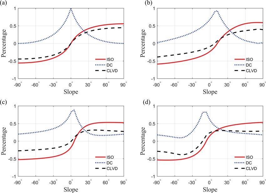
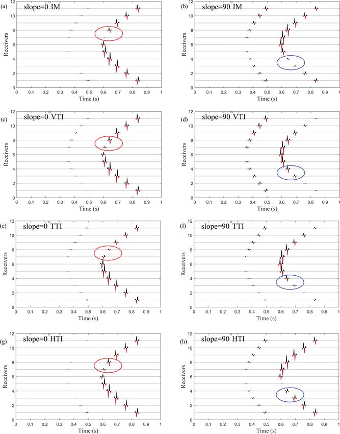
Journal of Geophysics and Engineering (2021) 18, 231–240 Yao and Wang
Table 2. The faulting style parameters

 Strike (°) Slip (°) Rake (°) ⎡−1 0 0⎤
 ⎢ ⎥
 MCLVD = M|max| ⎢ 0 −1
 L
Faulting style I 30 45 60 0⎥ , (10)
Faulting style II 325 25 −75 ⎢ 0 0 2⎥⎦
 ⎣

3. Methods and results ⎡1 0 0⎤
 ⎢ ⎥
3.1. The decomposition of the moment tensor MDC = (1 − 2 | |) M|max|
 L
 ⎢0 0 0 ⎥.
 ⎢0 0 −1⎥⎦
The microseismic source moment tensor can be decom- ⎣
posed into a double-couple (DC), a compensated linear vec- (11)
tor dipole component (CLVD), and an isotropic part (ISO) The non-DC components include ISO and CLVD com-
by eigenvalue decomposition (Knopoff & Randall 1970; ponents. ML is the sum of the DC and CLVD components,
 which is also called the deviatoric moment. Parameter is

 Downloaded from https://academic.oup.com/jge/article/18/2/231/6212761 by guest on 15 July 2021
Jost & Herrmann 1989):
 defined as
 M = MISO + MDC + MCLVD , (8) L
 M|min|
 =− , (12)
 | L |
where |M|max| |
 | |
 L L
 ⎡1 0 0⎤ where M|min| and M|max| are the eigenvalues of ML and their
 1 ⎢ ⎥ absolute values must be minimum and maximum. It can be
 MISO = trace (M) ⎢0 1 0⎥ , (9)
 3 seen that the value of ranges from [−1/2, 1/2]. If is
 ⎢0 0 1⎥⎦
 ⎣ greater than 0, then that source is tensile, and vice versa is

Figure 2. The percentage of the ISO, DC and CLVD components as a function of the inclination of the slip vector from the fault in various media by
using faulting style I. (a) IM, (b) VTI, (c) TTI and (d) HTI.

 234
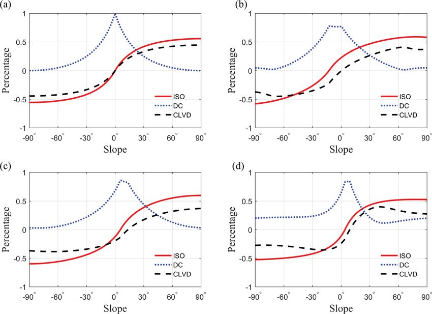
Journal of Geophysics and Engineering (2021) 18, 231–240 Yao and Wang

 Downloaded from https://academic.oup.com/jge/article/18/2/231/6212761 by guest on 15 July 2021
Figure 3. The percentage of the ISO, DC and CLVD components as a function of the inclination of the slip vector from the fault in various media by
using faulting style II (a) IM, (b) VTI, (c) TTI and (d) HTI.

compressed. When equals zero, it means the source is pure cluded that the source generated by isotropic solid is not af-
DC. For a non-DC source, the | | should be 1/2. fected by the faulting style. Finally, ISO and CLVD are always
 Based on this model, we can obtain the decomposition associated with each other in isotropic media, so if there are
results as a function of slope angle for different medium only ISO or CLVD elements in the decomposition of mo-
and faulting styles. Figure 2 shows how the slope angle and ment tensor, then the region where the source is located must
anisotropy affect the decomposition of the moment tensor. be anisotropic.
Figure 3 illustrates the same thing except with a different
faulting orientation. The DC percentage decreases, while the
ISO and CLVD percentage increase from the overall view. 3.2. Radiation pattern from a point source
It is easy to see from figure 2 parts b–d that anisotropy in- The mathematical forms of the far-field radiation pattern of
fluences the focal mechanisms. Although the slope angle is a dislocation source in homogenous media can be expressed
0, there is not a pure DC source. We can find that the ef- by (Aki & Richards 2002)
fect of anisotropy on the DC components is mainly concen-
trated on the cases of small slope angles. The ratio of the A Pi = i j k Mij , (13)
ISO component to the CLVD component in isotropic me-
dia is a fixed value, which is related to Vp /Vs . Although it is ( )
 A Si = ij − i j k Mij , (14)
no longer a definite value in anisotropic media, it also tends
 p
to be consistent in the case of high slope angle, which reveals where Ai and Asi are the radiation pattern in Xi direction of
that anisotropy mainly influences the shear source but has a P and S waves, respectively. Because i = xi ∕r, it is related to
little impact on the tensile source. Combined with figures 2 the azimuth and takeoff angle. Mij is a general moment tensor.
and 3, it can be clearly seen that the ISO components are not Figure 4 illustrates the far-field radiation pattern of P waves
sensitive to anisotropy, because the tendency of the ISO ratio calculated according to equation (13) in various mediums
curve approximately stays the same. Besides, it can be con- by using the general dislocation model I. For homogenous

 235
Journal of Geophysics and Engineering (2021) 18, 231–240 Yao and Wang

 Downloaded from https://academic.oup.com/jge/article/18/2/231/6212761 by guest on 15 July 2021
Figure 4. The P wave radiation pattern of general dislocation model I as a function of slope in different media. (a) IM, (b) VTI, (c) TTI and (d) HTI.

media (figure 4a), the P radiation pattern forms four uni- used to estimate the seismic radiated energy. These two coef-
form lobes for a shear source, but two lobes for high slopes. ficients can be computed by (Boore & Boatwright 1984)
With the increase of slope angle, the nodes in P wave radi-
 1 ∑
 N
ation pattern are suppressed. From figure 4b–d, changes in
 ⟨Rc ⟩ ≃ R ( , ) , (15)
P wave’s amplitude take place in the different mediums. In N i=1 c i i
addition, even though the slope angle is zero, it will not pro-
duce four average lobes in anisotropic media because it is no where Rc is the radiation pattern, is the azimuth and is
longer a pure DC source. Finally, we compare the radiation the takeoff angle. In most cases, the radiation coefficients over
pattern between homogenous media and anisotropic media. the whole focal sphere are Rp2 = 4∕15 and Rs2 = 2∕5 for shear
The conclusion is that the anisotropy will make a huge differ- faulting.
ence for a small slope angle while a large slope angle plays a The radiated energy ratio in the S and P wave is defined as
limited role and primarily changes the amplitude. (Randall 1973)
 2
 Es Rs2 Vp
 = 2 2. (16)
3.3. The radiated energy ratio of S/P waves Ep Rp Vs
Averages of P and S wave radiation coefficients calculated by Based on the previously discussed theory, suppose that
radiation patterns over all azimuths and takeoff angles are the medium is a Poisson’s solid; the radiated energy ration of

 236
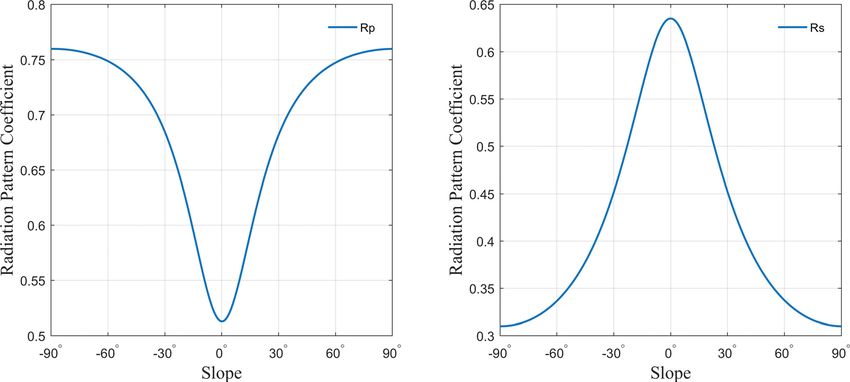
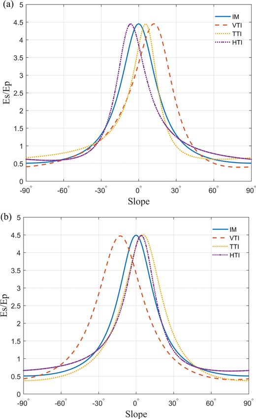
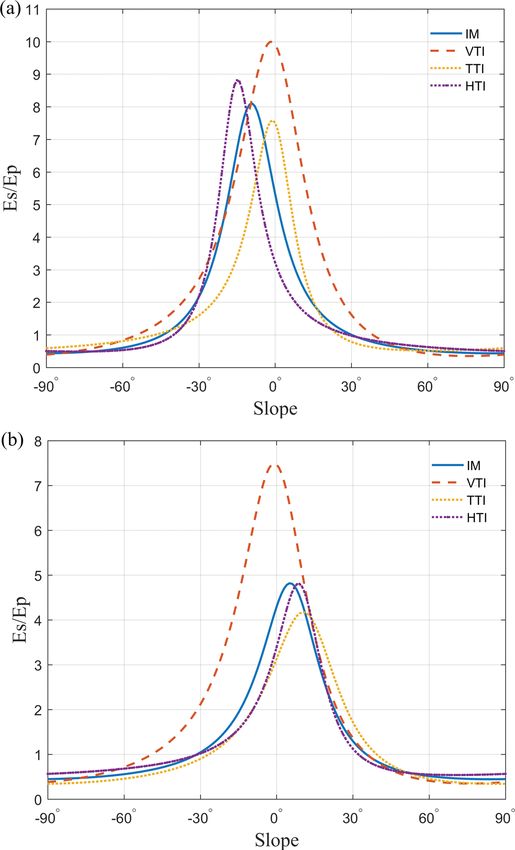
Journal of Geophysics and Engineering (2021) 18, 231–240 Yao and Wang

 Downloaded from https://academic.oup.com/jge/article/18/2/231/6212761 by guest on 15 July 2021
Figure 5. The relation between the radiation pattern coefficients of P and S waves as a function of the slope in homogenous media. The coefficients
are averaged over the whole focal sphere.

Es /Ep is 4.5, which can be defined as the lower bound. If the
Es /Ep ratio for a certain event is lower than 4.5, this can be
an indication that the source contains non-DC components
(Kwiatek & Ben-Zion 2013).
 The radiation pattern coefficients Rc used in equation
(15) is a function of focal mechanisms (including focal orien-
tation, slope angle and anisotropy), azimuth and takeoff an-
gle. We model the radiation pattern coefficients of P and S
waves versus the slope angle, which is shown in figure 5. The
radiation coefficients of P waves are boosted with the increase
of slope angle. On the contrary, the radiation of S waves de-
creases.
 Similarly, the Es /Ep ratio can also be calculated by the ra-
diation pattern coefficients in an anisotropic medium. In this
part, we consider both faults I and II, as the average radia-
tion pattern is related to the focal orientation. This is pre-
sented in figure 6, and as expected, we find the anisotropy
affects the Es /Ep ratio. The maximum value occurs at a cer-
tain offset. Compared with figure 2, it can be seen that the
energy ratio curve is related to the value of the DC com-
ponents because the peak of DC proportion and the Es /Ep
are incredibly close. However, it is difficult for receivers to
be located at the whole focal sphere, so we need to calcu-
late the other energy ratio without global coverage. Accord-
ing to Boore & Boatwright (1984), the ranges of takeoff an-
gles are 120° ≤ ≤180° for a close distance and the cor-
responding results are presented in figure 7. The maximum
Es /Ep ratio no longer approximates to 4.5 and it changes a lot.
To conclude, the value of the Es /Ep ratio is controlled firmly
by the slope angle for uniform coverage. However, for non-
uniform coverage, the value depends on the faulting style and Figure 6. The value of Es /Ep ratio over the focal sphere as a function of
anisotropy. slope angle for the various media by using (a) faulting style I and (b) fault-
 ing style II.

 237
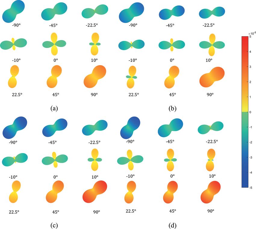
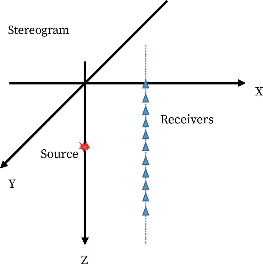
Journal of Geophysics and Engineering (2021) 18, 231–240 Yao and Wang

 Downloaded from https://academic.oup.com/jge/article/18/2/231/6212761 by guest on 15 July 2021
 Figure 8. The source-receiver configuration used for the simulation. The
 dislocation source is represented by the red star on the z-axis (fixed at
 1 km). The receivers (blue triangles) are placed along a straight line
 x = 1 km.

 figure). In the case of high slope angle, waveform changes on
 other receivers, especially below the blue ellipses, are mainly
 reflected in the amplitude, and this is also consistent with our
 previous analyses.

Figure 7. The value of Es /Ep ratio over the takeoff angles 120° to 180°as
a function of slope angle for the various media by using (a) faulting style I 4. Discussion
and (b) faulting style II.
 The general dislocation model is considered to be a reason-
 able model for explaining the focal mechanism and is suit-
 able for the calculation of moment tensor in anisotropic solid.
3.4. Synthetic seismograms for general dislocation sources
 Analyses of the decomposition of moment tensor, radiation
We use an analytical solution to calculate synthetic seismo- pattern, radiated energy ratio and seismic propagation char-
grams generated by a general dislocation source. The model acteristics are performed in this paper.
geometry is shown in figure 8, and we choose fault I as our Through the decomposition of the moment tensor, one
test model. A Ricker source time function with a frequency can find that the influence of anisotropy main occurs for small
of 50 Hz is used. The P wave speed is 3000 m s−1 , while the slope angles because the change of the DC component ratio
S wave velocity is 1731 m s−1 . The source depth is fixed at is more obvious. Besides, the ISO components are not sensi-
1 km. A total of 11 receivers are located on the x-z plane along tive to the media changes. More importantly, if there is only
a straight line x = 1000 m, they are in pairs and symmetric ISO or CLVD components in the decomposition, this indi-
about the line z = −1000 m. cates the source is located in anisotropic media.
 Figure 9 shows the vertical component synthetic seismo- The moment tensor radiation pattern reflects the char-
grams from a general dislocation source with slope 0° and 90° acteristics of a source more intuitively. For a P wave, a pat-
in various solids. It can be clearly seen that the P wave am- tern with two lobes generally means a tension source and has
plitude of the tensile source is always larger than the shear four lobes that show a shear source. Based on the previous
source regardless of the medium, which is consistent with analysis, the anisotropy at the lower slope angle directly af-
the previous analysis. Also, we found that when the medium fects the elongation and contraction of the positive and nega-
changes, the seismic record changes more significantly at tive lobes, and for a higher angle it does not affect the polarity
the polarity reversal (marked by red and blue ellipses in the but affects the change in amplitude.

 238
Journal of Geophysics and Engineering (2021) 18, 231–240 Yao and Wang

 Downloaded from https://academic.oup.com/jge/article/18/2/231/6212761 by guest on 15 July 2021

Figure 9. The vertical component synthetic seismograms from a general dislocation source with slope 0° and 90° in various solids.

 The radiated energy ratio is also affected by anisotropy. case, which means that the radiated energy ratio can still be
From this part’s analysis, we can see that the DC component used as one sign for judging whether the source is tensile
determines the ratio of Es /Ep to a large extent. Once the DC or not. This radiated energy ratio is calculated based on the
components proportion becomes larger, the radiated energy entire spherical radiation area. If the takeoff angle changes,
ratio will increase too. Therefore, the peak of the energy ra- the anisotropy makes a significant difference, care should be
tio will be shifted, but the degree of the offset will not be too taken in the inversion process.
large. However, it is interesting to note that although the peak The seismic records received on the ground or in the well
shifts, the value is basically the same as that of the isotropic are not only related to the focal mechanism and medium

 239
Journal of Geophysics and Engineering (2021) 18, 231–240 Yao and Wang

parameters but also related to the position of the receivers. Eisner, L., Williams-Stroud, S., Hill, A., Duncan, P. & Thornton, M., 2010.
Therefore, the seismic records shown in this paper, although Beyond the dots in the box: microseismicity-constrained fracture mod-
not global, still prove that anisotropy and slope angles can els for reservoir simulation, The Leading Edge, 29, 326–333.
 Fischer, T. & Guest, A., 2011. Shear and tensile earthquakes caused by fluid
affect the amplitude and polarity. injection, Geophysical Research Letter, 38, L05307.
 Foulger, G. R., Julian, B. R., Hill, D. P., Pitt, A. M., Malin, P. E. & Shalev,
 E., 2004. Non-double-couple microearthquakes at Long Valley Caldera,
5. Conclusion California, provide evidence for hydraulic fracturing, Journal of Volcanol-
 ogy and Geothermal Research, 132, 45–71.
In this paper, the manifestation of the seismic moment tensor Frohlich, C., 1994. Earthquakes with non-double-couple mechanisms,
in an anisotropic medium were analysed. Using anisotropy Science, 264, 804–809.
and slope angle as the main variables, we investigated the ef- Gao, F. & Wang, Y., 2020. Radiation pattern analyses for seismic multi-
fects of these two parameters on the decomposition of mo- parameter inversion of HTI anisotropic media, Journal of Geophysics and
ment tensor, radiation pattern, energy ratio and wave prop- Engineering, 17, 65–75.
 Gao, F., Wang, Y. & Wang, Y., 2018. Waveform tomography of two-
agation characteristics. The study showed that whether and
 dimensional three-component seismic data for HTI anisotropic media,
how much the moment tensor contains non-DC compo-

 Downloaded from https://academic.oup.com/jge/article/18/2/231/6212761 by guest on 15 July 2021
 Pure and Applied Geophysics, 175, 4321–4342.
nents depends on the type of anisotropy and the value of Jost, M. L. & Herrmann, R. B., 1989. A student’s guide to and review of
slope angle. When the slope angle is large, anisotropy plays moment tensors, Seismological Research Letters, 60, 37–57.
a limited role. However, anisotropy can be the main cause of Kawasaki, I. & Tanimoto, T., 1981. Radiation patterns of body waves due
the non-DC components, assuming the slope angle is small to the seismic dislocation occurring in an anisotropic source medium,
 Bulletin of the Seismological Society of America, 71, 37–50.
or even zero. We pointed out that faulting style also makes the Knopoff, L. & Randall, M. J., 1970. The compensated linear-vector dipole:
moment tensor complex in the anisotropic situation. This re- a possible mechanism for deep earthquakes, Journal of Geophysical Re-
quires that we should pay more attention to anisotropy in the search, 75, 4957–4963.
case of seismic moment inversion. Kwiatek, G. & Ben-Zion, Y., 2013. Assessment of P and S wave energy radi-
 ated from very small shear-tensile seismic events in a deep South African
 mine, Journal of Geophysical Research: Solid Earth, 118, 3630–3641.
Acknowledgements Pesicek, J. D., Cieślik, K., Lambert, M. A., Carrillo, P. & Birkelo, B., 2016.
 Dense surface seismic data confirm non-double-couple source mecha-
The research was funded by National Natural Science Founda- nisms induced by hydraulic fracturing Induced non-DC source mecha-
tion of China (grant no. 41774148), Key Research Program of nisms, Geophysics, 81, KS207–KS217.
Frontier Sciences, CAS (grant no. QYZDY-SSW-DQC009) and Pesicek, J. D., Šílený, J., Prejean, S. G. & Thurber, C. H., 2012. Deter-
National Science and Technology Major Project of China (grant mination and uncertainty of moment tensors for microearthquakes at
no. 2017ZX05032-003-001). Okmok Volcano, Alaska, Geophysical Journal International, 190, 1689–
 1709.
 Randall, M. J., 1973. The spectral theory of seismic sources, Bulletin of the
Conflict of interest statement: The authors declared that they Seismological Society of America, 63, 1133–1144.
have no conflicts of interest in this work. Rao, Y. & Wang, Y., 2020. Pore-pressure diffusion during water injection in
 fractured media, Geophysics, 85, MR51–MR56.
 Shi, Z. & Ben-Zion, Y., 2009. Seismic radiation from tensile and shear point
References dislocations between similar and dissimilar solids, Geophysical Journal
 International, 179, 444–458.
Aki, K. & Richards, P. G., 2002. Quantitative Seismology, 2nd edn, Univer- Šílený, J., Hill, D. P., Eisner, L. & Cornet, F. H., 2009. Non-double-couple
 sity Science Books, Sausalito, CA. mechanisms of microearthquakes induced by hydraulic fracturing, Jour-
Ben-Zion, Y. & Ampuero, J. P., 2009. Seismic radiation from regions sus- nal of Geophysical Research: Solid Earth, 114, B08307.
 taining material damage, Geophysical Journal International, 178, 1351– Song, F., Warpinski, N. R. & Toksöz, M. N., 2014. Full-waveform
 1356. based microseismic source mechanism studies in the Barnett Shale:
Boore, D. M. & Boatwright, J., 1984. Average body-wave radiation coeffi- linking microseismicity to reservoir geomechanics, Geophysics, 79,
 cients, Bulletin of the Seismological Society of America, 74, 1615–1621. KS13–KS30.
Cai, X., Yao, C. & Chen, X., 2011. Seismic moment tensor in anisotropic Staněk, F. & Eisner, L., 2013. New model explaining inverted source mech-
 ATI media: shear faulting, Chinese Journal of Geophysics, 54: 1772–1782. anisms of microseismic events induced by hydraulic fracturing, 83rd
Castro, R. R. & Ben-Zion, Y., 2013. Potential signatures of damage-related SEG Annual International Meeting, Expanded Abstracts, pp. 2201–2205.
 radiation from aftershocks of the 4 April 2010 (Mw 7.2) ElMayor- Thomsen, L., 1986. Weak elastic anisotropy, Geophysics, 51, 1954–1966.
 Cucapah Earthquake, Baja California, México, Bulletin of the Seismolog- Vavryčuk, V., 2001. Inversion for parameters of tensile earthquakes, Journal
 ical Society of America, 103, 1130–1140. of Geophysical Research, 106, 16339–16355.
Dufumier, H. & Rivera, L., 1997. On the resolution of the isotropic compo- Vavryčuk, V., 2005. Focal mechanisms in anisotropic media, Geophysical
 nent in moment tensor inversion, Geophysical Journal International, 131, Journal International, 161, 334–346.
 595–606. Vavryčuk, V., 2011. Tensile earthquakes: theory, modeling, and inversion,
Eaton, D. W. & Forouhideh, F., 2011. Solid angles and the impact of Journal of Geophysical Research: Solid Earth, 116, B12.
 receiver-array geometry on microseismic moment-tensor inversion, Walter, W. R. & Brune, J. N., 1993. Spectra of seismic radiation from a ten-
 Geophysics, 76, WC77–WC85. sile crack, Journal of Geophysical Research: Solid Earth, 98, 4449–4459.

 240
You can also read