IFIX 6.1 Creating High Performance Pictures - General Electric
←
→
Page content transcription
If your browser does not render page correctly, please read the page content below
iFIX 6.1
Creating High Performance Pictures

GE Digital   Proficy Historian and Operations Hub: Data Analysis in Context   1
Proprietary Notice
The information contained in this publication is believed to be accurate and reliable. However, General Electric Company assumes no
responsibilities for any errors, omissions or inaccuracies. Information contained in the publication is subject to change without notice.

No part of this publication may be reproduced in any form, or stored in a database or retrieval system, or transmitted or distributed in any
form by any means, electronic, mechanical photocopying, recording or otherwise, without the prior written permission of General Electric
Company. Information contained herein is subject to change without notice.

© 2020, General Electric Company. All rights reserved.

Trademark Notices
GE, the GE Monogram, and Predix are either registered trademarks or trademarks of General Electric Company.

Microsoft® is a registered trademark of Microsoft Corporation, in the United States and/or other countries.

All other trademarks are the property of their respective owners.

We want to hear from you. If you have any comments, questions, or suggestions about our documentation, send them to the following email
address:

doc@ge.com

Table of Contents

   Creating High Performance Pictures                                         1

   Upgrading to Support GE Web HMI                                            1

   Understanding GE Web HMI Pictures                                          1

     GE Web HMI Element Support                                               2

       Supported GE Web HMI Elements                                          2

       Unsupported GE Web HMI Elements                                        3

   Enabling High Performance Graphics in iFIX                                 3

   Creating Pictures for Export to GE Web HMI                                 4

     Using the Web HMI Toolbox                                                5

     Using the High-Performance Color Box                                     6

     Using High-Performance Dynamos                                           6

       High-Performance Arrow Dynamos (HPArrows.fds)                          7

          Dynamo Set                                                          7

          Dialog Box                                                          8

       High-Performance Linear Gauges Dynamos (HPLinearGauges.fds)            8

          Dynamo Set                                                          8

          Dialog Box                                                          9

          Tag Group Substitution                                              13

       High-Performance Linear Gauge for Historian (HPLinearGaugesHist.fds)   13

          Dynamo Set                                                          13

          Dialog Box                                                          13

       High-Performance Mixer Dynamos (HPMixer.fds)                           17

          Dynamo Set                                                          17

          Dialog Box                                                          18

       High-Performance Motors Dynamos (HPMotors.fds)                         19

          Dynamo Set                                                          19

          Dialog Box                                                          19

       High-Performance Pipes Dynamo (HPPipes.fds)                            20

          Dynamo Set                                                          20

© 2020 General Electric Company. All rights reserved.                              i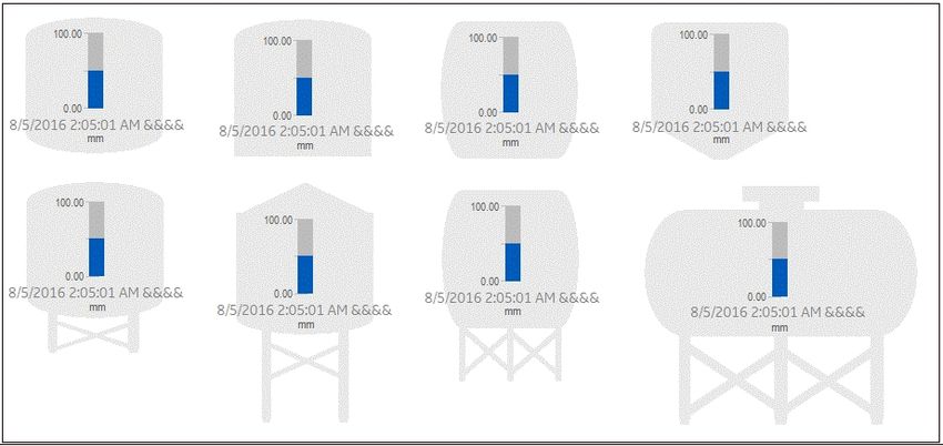
Dialog Box                                                                                  20

         High-Performance Pump Dynamos (HPPump.fds)                                                    21

           Dynamo Set                                                                                  21

           Dialog Box                                                                                  21

         High-Performance Tank Dynamos (HPTanks.fds)                                                   22

           Dynamo Set                                                                                  22

           Dialog Box                                                                                  23

         High-Performance Tank Animation Dynamos (HPTanksAnim.fds)                                     23

           Dynamo Set                                                                                  23

           Dialog Box                                                                                  24

           Tag Group Substitutions                                                                     27

         High-Performance Tank Animations for Historian (HPTanksAnimHist.fds)                          28

           Dynamo Set                                                                                  28

           Dialog Box                                                                                  28

         High-Performance Valve Dynamos (HPValves.fds)                                                 32

           Dynamo Set                                                                                  32

           Dialog Box                                                                                  33

       Controlling Data Sources in a Picture by Group Selection                                        34

       Automatically Binding Child Assets to Click Zones using Group Names                             35

       Referencing a Model Property in an Animation                                                    36

       Picture Design Tips                                                                             36

     Publishing and Exporting Pictures to Web HMI                                                      37

       Publishing iFIX Pictures to Web HMI                                                             37

       Exporting GE Web HMI Pictures to a Folder                                                       38

         Troubleshooting Tips                                                                          39

       Publish to Web HMI Dialog Box                                                                   39

         Select All                                                                                    39

         Picture List                                                                                  39

         Export Mimic Path                                                                             39

         Overwrite Existing Export Files                                                               39

         Publish to Web HMI                                                                            39

ii                                                    © 2020 General Electric Company. All rights reserved.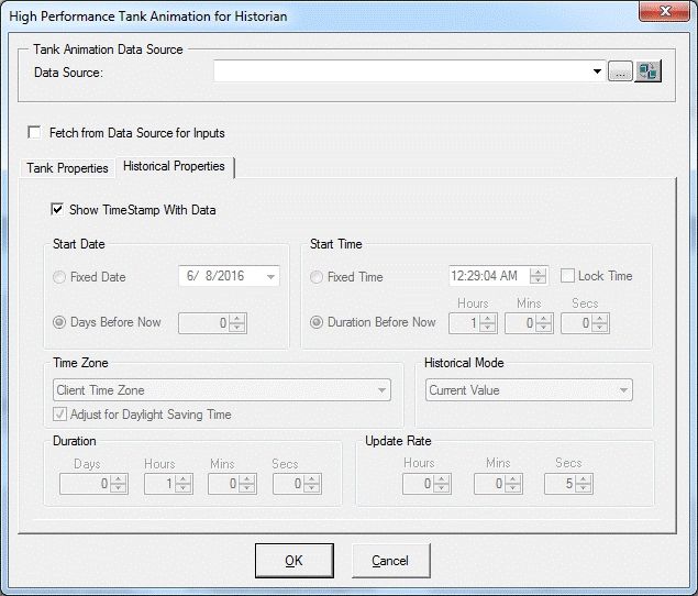
Overwrite Existing Mimics in Web HMI                   39

       Publish                                                40

       Cancel                                                 40

     Publish to Web HMI - Connection Information Dialog Box   40

       Server Name                                            40

       Port                                                   40

       User Name                                              40

       Password                                               40

       Require Trusted Connection                             40

       View Certificate                                       40

     Troubleshooting the Publishing Process                   40

   Index                                                      41

© 2020 General Electric Company. All rights reserved.              iii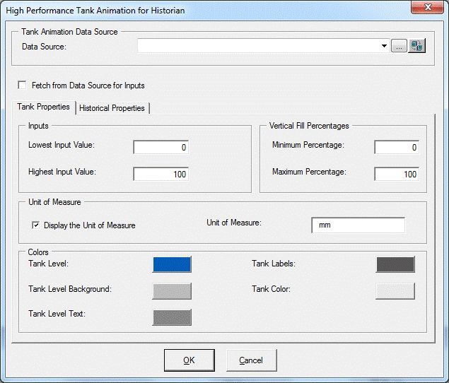
Creating High Performance Pictures

High-performance HMI displays provide information to operators in a concise and effective way that max-
imizes their ability to assess the state of a process. By minimizing visual distractions and irrelevant inform-
ation, operators can more readily determine what actions they need to take. iFIX provides graphic tools
including dynamos, a high-performance color palette, and a Web HMI toolbox that are designed to help you
create pictures that follow industry guidelines for High-Performance HMI. The use of high performance
graphic tools and settings are recommended for pictures intended for export to GE Web HMI. However, you
can take advantage of high performance tools and design principles when designing your traditional iFIX pic-
tures as well.

You can export and save GE Web HMI picture files to a folder. The exported files are in JavaScript Object
Notation (JSON) format. When these exported files are uploaded to the GE Web HMI server, they can be
viewed in the GE Web HMI browser client.

Once you have installed iFIX with support for GE Web HMI and high performance graphics, a Web HMI
group appears in WorkSpace in the Tools tab in Ribbon view. The Web HMI group contains two buttons to
help you create and export Web HMI pictures. In addition, high performance Dynamos are installed to help
you create simple, concise graphics with minimal effort. For more information on using iFIX with support for
GE Web HMI, refer to the following sections:

    l   Creating Pictures for Export to GE Web HMI
    l   Exporting GE Web HMI Pictures

 NOTE: This documentation assumes you are familiar with the traditional iFIX help and picture creation meth-
 ods and tools. For more information, refer to the Creating Pictures e-book.

   Upgrading to Support GE Web HMI

 If you are upgrading from a previous version of iFIX and you want to use the high-performance features
 to create pictures for a GE Web HMI environment, you must perform your installation in the following
 order:

     1. iFIX 5.8
     2. iFIX 5.8 SP2
     3. Web HMI bootstrapper install

 The Web HMI bootstrapper install updates the SCU for Web HMI, and adds the DataDistributor/Alarm
 Gateway configurations automatically.
 NOTE: If you install iFIX 5.8 SP2 after the Web HMI bootstrapper, you must add the DataDistributor and Alarm
 Gateway to the iFIX tasks manually. For more information, refer to the Setting up the Environment e-book.

 Understanding GE Web HMI Pictures

 iFIX, with support for GE Web HMI and high-performance graphics, delivers the necessary com-
 ponents to create high-performance Web HMI graphics to display in the GE Web HMI browser cli-
 ent. As with traditional iFIX pictures, GE Web HMI pictures include objects and data sources that
 represent your process. You create GE Web HMI pictures by inserting and manipulating objects and

© 2020 General Electric Company. All rights reserved.                                                             1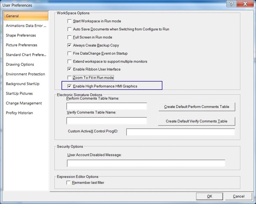
data sources in your pictures. Not all objects that are supported in traditional iFIX pictures are sup-
 ported in GE Web HMI pictures. For example, GE Web HMI supports line elements but does not sup-
 port pipe elements. For more information on GE Web HMI object support, refer to the GE Web HMI
 Element Support section.

 To create and optimize high performance graphics, the high-performance HMI Graphics check box
 in the User Preference - General Tab dialog box must be enabled (default). This sets the high-per-
 formance color box as the default color palette, and also sets the high-performance shape, color,
 and font settings.

 Once iFIX with support for GE Web HMI and high-performance graphics is installed, the following
 Web HMI buttons appear in Ribbon view in the Web HMI group of the Tools tab in WorkSpace:

     l   Toolbox
     l   Export Picture

 The Toolbox contains objects, animations, and picture creation tools as described in the Using the
 Web HMI Toolbox section. This Toolbox also provides a high-performance color box you can use to
 enhance your iFIX pictures. For more information on the color box, refer to the Using the High-Per-
 formance Color Box section.

 Once you create and save the picture, use the Export Picture button to export the file to a default
 folder or a folder location of your choosing. This folder contains corresponding log and zip files for
 each file exported. For more information, refer to the Exporting GE Web HMI Pictures section.

GE Web HMI Element Support

 The following sections provide a listing of objects that the GE Web HMI client does and does not sup-
 port.

 Supported GE Web HMI Elements
     l   Shapes (rectangle, rounded rectangle, oval, chord, polygon, pie, arc, line, polyline, line con-
         nector, and right angle line connector)
         IMPORTANT: Scripting, pipes, and pipe connectors are not supported. For more information on
         unsupported elements, refer to the Unsupported Elements section.

     l   Bitmaps (are converted to .png files during export)

     l   The IsSelectable Property is exported for group objects. When set to True, it indicates the
         ability to control one or more data sources associated with objects contained in the group. For
         more information, refer to the Controlling Data Sources in a Picture section.

2                                                       © 2020 General Electric Company. All rights reserved.
l   Groups
      l   Datalink including Historical Datalink
      l   Animations
              l   Fill - vertical and horizontal
              l   Rotate (not supported for Rounded Rectangles and Ovals)
              l   Color Foreground/Background/Edge
              l   Visibility
      l   Text (the default is GE Inspira font, 12 points)
      l   Dynamos
      l   Expressions (simple and complex)
      l   iFIX or Historian data sources or references to model properties

 You can find additional information on using supported elements in the Creating Pictures ebook.

 Unsupported GE Web HMI Elements
      l   Scripting
      l   Pipe objects and pipe connectors
      l   Push Button
      l   OLE objects and ActiveX controls
      l   Variable
      l   Timer
      l   Event
      l   Time
      l   Date
      l   Alarm Summary
      l   Chart
      l   Linear Animation of scale and position
      l   Experts (open picture, close picture, replace, picture, refresh picture, and data entry)
      l   VisionX Controls (data, grid, list box, and combo box)
      l   Animating objects using another object’s properties
      l   Data Sources that are not FIX32 or Historian data sources

 Enabling High Performance Graphics in iFIX

The User Preferences - General Tab dialog box provides a check box to enable or disable high performance
HMI graphics as shown in the following illustration. By default, this check box is enabled when you first
start WorkSpace.

 Enabling this check box helps you to create high performance pictures for export to the GE Web

© 2020 General Electric Company. All rights reserved.                                                       3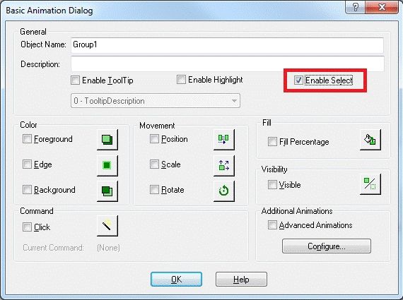
HMI client or iFIX pictures that use colors and graphic settings that are optimized for high performance.
High performance pictures include default settings for the following:

    l   High performance color box
    l   GE Inspira font (12 points)
    l   High performance shape foreground colors

For more information on the User Preferences - General tab, refer to the Understanding iFIX ebook.

Creating Pictures for Export to GE Web HMI

To create a new iFIX high performance picture for export to GE Web HMI, use the Web HMI Toolbox to
select objects and to configure animations. The Web HMI Toolbox includes only those objects and
experts that are supported for export to GE Web HMI pictures. If you use an existing picture, unsup-
ported objects and scripts are not exported. The log file that is generated during the JSON export lists
those elements that were not exported. Therefore, it is recommended that you create new pictures for
your GE Web HMI environment in order to avoid reworking existing pictures.

The Web HMI Toolbox can be toggled on and off by clicking the Toolbox button found on the Tools tab in
the Web HMI group of the WorkSpace ribbon. Once enabled, you can use any of the Web HMI Toolbox
elements to create your pictures. For more information on the toolbox, refer to the Using the Web HMI
Toolbox sections.

4                                                    © 2020 General Electric Company. All rights reserved.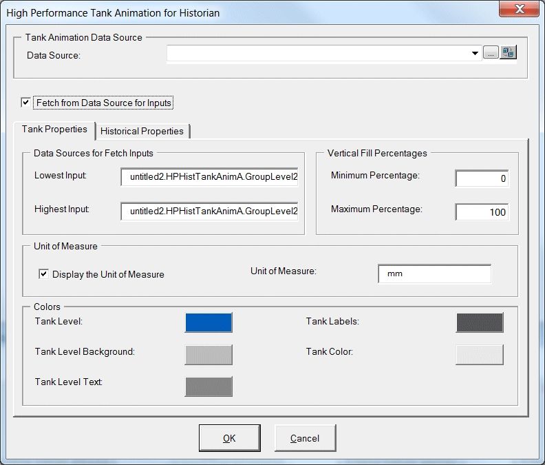
The elements in the Toolbox (and Dynamos) are designed to use the high-performance Color Box
 (palette). This color box contains the colors you need to assign high-performance HMI color to objects in
 your pictures. For more information on the color box, refer to the Using the High-Performance Color Box
 section.

 You can configure animations in your high-performance pictures. Animations can be configured to use
 iFIX tags, Historian tags, or model references from your Web HMI model. Model references entered
 manually in the data sources field of the animation must begin and end with an @ (at sign). For example,
 to use the value of the model reference Pump1.Speed, enter @Pump1.Speed@ in the data source of
 the animation expert. For more information on creating animations, refer to the Creating Pictures ebook.
 IMPORTANT: Even though the model reference in the data source for Web HMI pictures may look the same
 as the iFIX "tag group symbol," Web HMI does NOT need or use tag groups.

 In addition, you can modify a data source within a picture using the group object's IsSelectable prop-
 erty. When a data source is contained in a group object with the IsSelectable property set to True,
 you can click on the group in the display and enter a new value. This new value is written to the data-
 base. For more information on controlling data sources, refer to the Controlling Data Sources in a Picture
 section.

 iFIX, with support for GE Web HMI, also provides pre-built high performance Dynamos. Use these
 Dynamos to create a consistent design in your high-performance pictures. For a description of these
 high-performance Dynamos, refer to the Using High-Performance Dynamos section.

Using the Web HMI Toolbox

 The Web HMI Toolbox contains buttons for objects and picture composition tools that allow you to
 quickly create high performance HMI pictures. You can click and drag the Web HMI Toolbox to a pos-
 ition anywhere on your picture, or click and drag one of its edges to resize it.

 The Web HMI Toolbox automatically appears by default when high performance HMI graphics are
 enabled in the User Preferences - General Tab dialog box.

 You can disable the Web HMI Toolbox by toggling the Toolbox button on the Tools tab in the Web HMI
 group of the WorkSpace ribbon.

 The following table lists the names of the Web HMI Toolbox buttons. The layout of the cells in this table
 mimics the layout of the corresponding buttons in the Web HMI Toolbox. A description of each button
 can be found in the Creating Pictures ebook.

  Pointer                                            Rounded
                                                                                        Poly-
  Selec-     Cut       Copy     Paste      Rectangle Rect-   Oval              Chord             Pie
                                                                                        gon
  tion                                               angle
                                          Right Line
                       Polylin- Line Con-                         Datalink              Set      Toggle
  Arc        Line                         Con-       Text                      Bitmap
                       e        nector                            Stamper               Color    Grid
                                          nector
             Space
  Space                                                           Align Hori- Align
             Evenly    Align               Align Bot- Align                                      Ungrou-
  Evenly                        Align Left                        zontal      Vertical Group
             Hori-     Top                 tom        Right                                      p
  Vertical                                                        Center      Center
             zontal
  Bring to   Send to   Set      Display    Fill Expert Rotate     Fore-        Vis-     Undo     --

© 2020 General Electric Company. All rights reserved.                                                         5
ground
ibility
Front Back Layer Layer Expert Color
Expert
Expert
Using the High-Performance Color Box
The high-performance Color Box contains the colors you need to assign high performance HMI colors to
your objects. It offers color consistency in your pictures, and can be accessed from anywhere in the iFIX
WorkSpace. An example of the high-performance Color Box follows.
The Color Box contains the following two drop-down lists to help you apply color to your pictures:
NOTE: The use of gradient color is discouraged when designing pictures for GE Web HMI.
l Property - Lets you select foreground, background, edge, or fade colors if applicable for a selected
object. This dialog box is accessed by right-clicking the object, pointing to Color, and then choosing
Fade, Foreground, Background, or Edge from the drop-down menu that appears. The default color is
gray.
l Color Set - Lets you select a color set from the drop-down list for the selected object(s). The Color Set
dialog box is accessed by clicking the Color button on the Tools (Classic view) or on the Format tab in
the Styles group (Ribbon view) or the Toolbox, if enabled. The default color is gray
When launched from the Format Tab in Ribbon view, the dialog box is modeless, allowing you to select
different shapes in your picture while the dialog box remains on your screen. You can color as many
objects as you like using this box, and you can choose which property of the selected object or objects
you want to modify.
For more information on working with color, refer to the Creating Pictures ebook.
Using High-Performance Dynamos
As explained in the Creating Pictures e-book, a dynamo is a group of objects that make up a custom
6 © 2020 General Electric Company. All rights reserved.object that provides consistency when used in multiple pictures across your system. When you
install iFIX 5.8 SP2, high performance Dynamo sets are available for you to use as well as tra-
ditional Dynamo sets. (High Performance Dynamos do not override traditional Dynamos.)
Dynamo set files have an .fds extension and are located in the following directory by default C:\Pro-
gram Files (x86)\GE\iFIX\PIC.
High-performance dynamo sets include the following files:
l HPArrows.fds
l HPLinearGauges.fds
l HPLinearGaugesHist.fds
l HPMixers.fds
l HPMotors.fds
l HPPipes.fds
l HPPumps.fds
l HPTanks.fds
l HPTankAnim.fds
l HPTanksAdminHist.fds
l HPValves.fds
NOTES:
l To optimize dynamo high-performance behavior, it is recommended to enable high-performance graphics
in the User Preference - General Tab.
l The following currently apply:
o HPTanksAnim and HPLinearGauges dynamos do not support Historian. If you plan to use
Historian tags, use the HPLinearGaugesHist and HPTanksAnimHist dynamos.
o HPLinearGaugesHist and HPTanksAnimHist support Historian data sources only.
o HPMixers, HPPumps, HPValves, HPMotors, HPTankAnim, and HPLinearGauges dynamos
support Historian and OPC as data sources. Historian data sources only support the GE
Historian current value.
o HPMixers, HPPumps, HPValves, HPMotors, HPTankAnim, and HPLinearGauges Data
Sources do not support complex mathematical expressions, Picture object properties, or
Global Variables.
You can drag and drop a high-performance Dynamo object from the set into your picture. A Dynamo dialog
box appears when you double-click on a Dynamo or when the Dynamo is first copied into a new picture. For
more information on using Dynamos, refer to the Creating Pictures e-book.
High-Performance Arrow Dynamos (HPArrows.fds)
Dynamo Set
The high-performance Arrow Dynamo set includes the following dynamos.
© 2020 General Electric Company. All rights reserved. 7Dialog Box
A high-performance Arrow Dynamo dialog box contains the following property:
l Arrow Color - You can accept the default Arrow color or select a new color from the high performance
Color Box. The following illustration shows the default Arrow color.
High-Performance Linear Gauges Dynamos (HPLinearGauges.fds)
Dynamo Set
The high-performance Linear Gauges dynamo set is designed for real time data and includes the fol-
lowing horizontal and vertical dynamos.
NOTES:
l This Dynamo Set is currently designed for iFIX real time data, OPC data items, and tag groups with
iFIX tags or OPC data items.
l A datalink within this dynamo will show the current value in run mode, which may not scale with the
Lowest and Highest Input values.
l Currently, this Dynamo does not support complex mathematical expressions, Picture object prop-
erties, or Global Variables
8 © 2020 General Electric Company. All rights reserved.Dialog Box
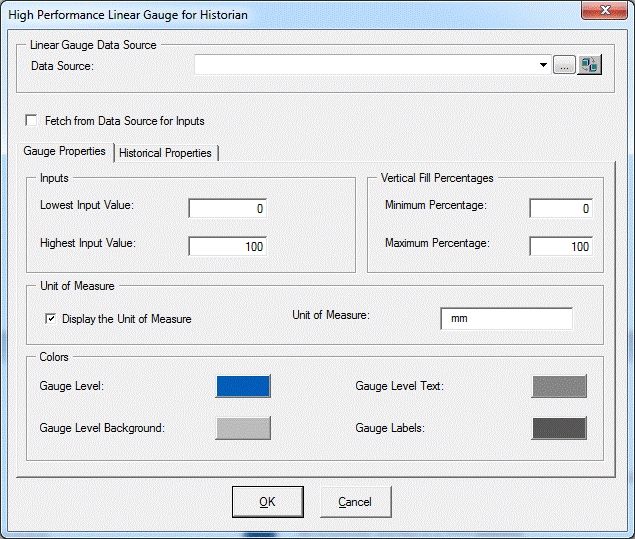
The high-performance Linear Gauge Dynamo dialog box contains the following properties:
l Linear Gauge Data Source - Allows you to enter the data source that animates the Linear Gauge
Dynamo. Click the browse button (...) to browse data sources in the Expression Builder. Click
the down button to view the last data sources you used. These dynamos are designed to support
real time data only.
l Fetch from Data Source for Inputs
o When this box is not checked, it provides Input dialog boxes to specify the Lowest and
Highest input values and the Unit of Measure.
© 2020 General Electric Company. All rights reserved. 9o When this box is checked, it provides dialog boxes for the data sources for Fetch Inputs
and generates the default data sources with default EGU fields based on the main data
source you specified. Default data sources for the Lowest Input, Highest Input, and Unit
of Measure can be modified if needed. When you enable this checkbox and specify:
l A data source, then default fields for the data source are used for fetch. If neces-
sary, you can edit the data sources for fetch inputs.
For example, the following screen shows the default data sources with default
fields for the Lowest Input, Highest Input, and Unit of Measure generated from the
main data source, Fix32.FIX.AAKMM.F_CV. The Lowest and Highest Input values
and the Unit of Measure will be read from those data sources in run mode.
10 © 2020 General Electric Company. All rights reserved.NOTES:
o If you are using iFIX tag item (A_CV or F_CV syntax) through iFIX’s OPC
server, then the default lowest and highest input datasources and UoM data
source are automatically generated as same as straight iFIX tag syntax.
o If you are using a third party OPC driver, then iFIX does not know the EGU
data source items for the lowest and highest since it is vendor dependent;
therefore, you must specify items for the datasources for Fetch Inputs
The Default is the same for the main datasource and you can modify it.
l A tag group as a data source, then the tag group substitution is expected to be
defined with no fields. The Lowest and Highest Input values and the Unit of Meas-
ure are read from the default fields of the tag group symbol. For example, if you
define the tag group symbol as tag1, and the substitution is Fix32.FIX.AI0, then
you must specify @tag1@ or @tag1@.F_CV in the data source. Refer to the Tag
Group Substitution for more information on permissible tag group substitutions.
© 2020 General Electric Company. All rights reserved. 11NOTE: Data sources for Fetch Inputs do not support complex mathematical expressions, Picture object
properties, or Global Variables.
l Vertical or Horizontal Fill Percentages - Provides a dialog box for the minimum and maximum per-
centages to use for the GaugeLevel animation in the dynamo.
l Colors - Allows you to accept the default gauge level and label colors or select a new color from
the high performance Color Box. The previous illustration shows the default Gauge Level and
Gauge Label colors.
l A check box allows you to select (or deselect) to display the Unit of Measure in the dynamo.
l Alarm Limits - Allows you to display labels for the defined alarm limits in run mode. The optional
Enable Smart Limits feature allows you show only the alarm limits that you are approaching on
the gauge. Smart Limits help if you have multiple of these Dynamos on screen. In this case, the
Alarm Limits labels can crowd the picture and could possibly cause confusion. Smart labels
provide the situational awareness with less clutter.
12 © 2020 General Electric Company. All rights reserved.Tag Group Substitution
You can use the following table to guide you with using Tag Group substitutions.
Tag Group Sym- Tag Group Sub- Data Source Result
bol stitution in Dynamo
Fix32.FIX.AI0 l @Sample1@.F_CV OK
Sample1
l @Sample1@
FIX.AI0 l @Sample2@.F_CV OK
Sample2
l @Sample2@
AI0 l @Sample3@.F_CV It works in general, but is
l @Sample3@ not supported for this
Sample3 dynamo. A Warning mes-
sage will appear in run
mode.
Fix32.FIX.AI0.F_CV l @Sample4@ It works in general, but is
not supported for this
Sample4 dynamo. A Warning mes-
sage will appear in run
mode.
High-Performance Linear Gauge for Historian (HPLinearGaugesHist.fds)
Dynamo Set
The high-performance Linear Gauges for Historian dynamo set is designed to support Historian data
sources only. It includes the following horizontal and vertical dynamos.
NOTES:
l This dynamo set is designed for Historian data sources, or tag groups with Historian tags.
l A Historical Data Link within this dynamo shows the current value or specified historical data in
run mode, which may not scale with the Lowest and Highest Input values.
l Currently, the dynamos do not support complex mathematical expressions, Picture object prop-
erties, or Global Variables.
Dialog Box
The High-Performance Linear Gauge for Historian dynamo dialog box contains the following prop-
erties:
© 2020 General Electric Company. All rights reserved. 13l Linear Gauge Data Source - Allows you to specify the data source that animates the Lin-
ear Gauge Dynamo. Click the browse button (...) to browse data sources in the Expression
Builder. Click the down button to view the last data sources you used. These dynamos are
designed to support GE Historian data sources only.
l Fetch from Data Source for Inputs - When enabled, lets you specify the data source for the
inputs.
o When this box is not checked, the Lowest and Highest Input Value fields are access-
ible in the Inputs section of the dialog box. These fields can be modified by the user.
o When this box is checked, the fields contain dialog boxes with the data sources for
the Fetched Inputs value in the Gauge Properties tab. The Lowest Input Value and the
Highest Input Value fields show default data sources for the animation object's
LoInValue and HiInValue properties.
l Gauge Properties Tab - Opens dialog boxes for Inputs or the data sources for Fetched
Inputs based on Fetch from Data Source for Inputs status and other settings for animation,
14 © 2020 General Electric Company. All rights reserved.Unit of Measure, and Colors.
Gauge Property Description
Allow you to enter the lowest and highest input values to
Inputs use.
Allows you to specify data sources for Lowest and Highest
Inputs.
The default data sources are the animation object’s
Fetch from Data Source for LoInValue and HiInValue properties. iFIX reads the EGU (Lo
Inputs and Hi value) from Historian and then sets them to those
properties in run mode.
In most cases, you do not need to change them. However,
you can use iFIX tags for a workaround if needed.
Provides a dialog box for the minimum and maximum per-
Fill Percentages centages to use for the GaugeLevel animation in the
dynamo.
Allows you to select (or de-select) to display the Unit of
Units of Measure Measure in the dynamo and specify strings for the Unit of
Measure.
Allows you to accept the default gauge level and label colors
or select new colors from the high performance Color Box.
Colors
The previous illustration shows the default Gauge Level and
Gauge Label colors.
NOTE: Data sources for Fetch Inputs do not support complex mathematical expressions,
Picture object properties (other than default animation object's LoInValue and HiInValue), or
Global Variables.
l Historian Properties Tab - Opens dialog boxes to select properties to use with Historian
tags.
© 2020 General Electric Company. All rights reserved. 15Property Description
When the check box is selected, a timestamp is
Show Time Stamp with Data shown with the data.
Default = Checked.
Lets you enter the date to start the data collection.
l Fixed Date - Lets you specify a specific date
to start gathering data.
l Days Before Now - Lets you specify the num-
Start Date
ber of days before today to start gathering
data.
Default: Disabled since the Historical Mode is the
Current Value.
Lets you enter the time to begin to collect data.
Start Time
l Fixed Time - Lets you enter a specific time to
16 © 2020 General Electric Company. All rights reserved.start gathering data.
l Lock - Locks the current time, even if you
change the timezone in the Date and Time
Properties dialog box in the Control Panel.
This field is only available when you des-
ignate a specific time to start the display
using the Fixed Time field.
l Duration Before Now - Allows you to specify
the hours, minutes, and seconds before now
(current date/time) to start the data col-
lection.
Default: Disabled since the Historical Mode is the
Current Value.
Allows you to select the time zone for the data.
You can also use the check box to adjust the time to
Time Zone Daylight Savings Time.
Default: Disabled since the Historical Mode is the
Current Value.
Provides a drop-down menu to select the Historian
Historical Mode data mode you want to use.
Default: Current Value
Specifies the duration time in days, hours, minutes,
and seconds.
Duration
Default: Disabled since the Historical Mode is the
Current Value.
Specifies the update (refresh) rate in hours, minutes,
Update Rate
and seconds.
High-Performance Mixer Dynamos (HPMixer.fds)
Dynamo Set
The high-performance Mixer Dynamo set includes the following dynamos.
© 2020 General Electric Company. All rights reserved. 17Dialog Box
The high-performance Mixer Dynamo dialog box contains the following properties:
l Mixer Data Source - Allows you to enter the data source that animates the Mixer Dynamo. Click
the browse button (...) to browse data sources in the Expression Builder. Click the down button to
view the last data sources you used. These dynamos are designed to support iFIX real time data,
OPC, and GE Historian. GE Historian data source is supported for the current value.
NOTE: Currently, this dynamo does not support complex mathematical expressions, Picture
object properties, or Global Variables.
l Mixer Values - Allow you to specify the following:
o Mixer Off and Mixer On values - Specifies the values to turn the mixer on and off. You can
accept the default colors for these values or select new colors from the high performance
Color Box. The following illustration shows the default Mixer Off and On Value colors.
o Tolerance - Specifies the rounding factor to be used for the Mixer Off and Mixer On values.
Typically, iFIX uses this value when comparing a process value to a target value. If the
process value is within the specified tolerance, iFIX assumes the two values are equal.
For example, if the target value is 1.0, the tolerance is 0.1, and the current value of a data
source is 0.8, iFIX does not assume the two values are equal because the data source is
not within the specified tolerance. The value must within the range 0.9 to 1.1 to equal the
target value.
18 © 2020 General Electric Company. All rights reserved.High-Performance Motors Dynamos (HPMotors.fds)
Dynamo Set
The high-performance Motors Dynamo set includes the following dynamos.
Dialog Box
The high-performance Motor Dynamo dialog box contains the following properties:
l Motor Data Source - Allows you to enter the data source that animates the Motor Dynamo. Click
the browse button (...) to browse data sources in the Expression Builder. Click the down button to
view the last data sources you used. These dynamos are designed to support iFIX real time data,
OPC, and GE Historian. GE Historian data source is supported for the current value.
NOTE: Currently, this dynamo does not support complex mathematical expressions, Picture
object properties, or Global Variables.
l Motor Values - Allows you to specify the following:
o Motor Off and Motor On values - Specifies the values to turn the motor on and off. You can
accept the default colors for these values or select new colors from the high performance
Color Box. The following illustration shows the default Motor Off and On Value color (and
Accent color).
o Tolerance - Specifies the rounding factor to be used for the Motor Off and Motor On val-
ues. Typically, iFIX uses this value when comparing a process value to a target value. If
the process value is within the specified tolerance, iFIX assumes the. Typically, iFIX uses
this value when comparing a process value to a target value. If the process value is within
the specified tolerance, iFIX assumes the two values are equal. For example, if the target
value is 1.0, the tolerance is 0.1, and the current value of a data source is 0.8, iFIX does
not assume the two values are equal because the data source is not within the specified
tolerance. The value must within the range 0.9 to 1.1 to equal the target value.
l Motor Accent Color - Lets you accept the default color or select a new color from the high per-
formance Color Box.
© 2020 General Electric Company. All rights reserved. 19High-Performance Pipes Dynamo (HPPipes.fds )
Dynamo Set
The high-performance Pipes dynamo set includes the following dynamos.
Dialog Box
The high-performance Pipes dialog box contains the following properties:
l Pipe Settings - Lets you accept the default color or select a new color from the high performance
Color Box. You can also change the Pipe Thickness if you wish. The following illustration shows the
default Pipe Color.
20 © 2020 General Electric Company. All rights reserved.High-Performance Pump Dynamos (HPPump.fds)
Dynamo Set
The high-performance Pump dynamo set includes the following dynamos.
Dialog Box
The high-performance Pump Dynamo dialog box contains the following properties:
l Pump Data Source - Allows you to enter the data source that animates the Pump Dynamo. Click
the browse button (...) to browse data sources in Expression Builder. Click the down button to
view the last data sources you used. These Dynamos are designed to support iFIX real time
data, OPC, and GE Historian. GE Historian data source is supported for the current value.
NOTE: Currently, this dynamo does not support complex mathematical expressions, Picture
object properties, or Global Variables.
l Pump Values - Allow you to enter the following:
o Pump Off and Pump On values - Specifies the values to turn the pump on and off. You can
accept the default colors for these values or select new colors from the high performance
Color Box. The following illustration shows the default Pump Off and On Value color (and
© 2020 General Electric Company. All rights reserved. 21Accent color).
o Tolerance - Specifies the rounding factor to be used for the Pump Off and Pump On val-
ues. Typically, iFIX uses this value when comparing a process value to a target value. If
the process value is within the specified tolerance, iFIX assumes the two values are
equal. For example, if the target value is 1.0, the tolerance is 0.1, and the current value of
a data source is 0.8, iFIX does not assume the two values are equal because the data
source is not within the specified tolerance. The value must within the range 0.9 to 1.1 to
equal the target value.
High-Performance Tank Dynamos (HPTanks.fds)
Dynamo Set
The high-performance Tank dynamo set includes the following dynamos.
22 © 2020 General Electric Company. All rights reserved.Dialog Box
The high-performance Tank Dynamo dialog box contains the following properties:
l Tank Color - Lets you accept the default Tank color or select a new color from the high per-
formance Color Box. The following illustration shows the default Tank color.
High-Performance Tank Animation Dynamos (HPTanksAnim.fds)
Dynamo Set
The high-performance Tank Animations Dynamo set is designed for real-time datasources only. This
dynamo set includes the following dynamos.
NOTES:
l This dynamo set is currently designed for iFIX real time data, OPC data items, and tag groups with iFIX
tags or OPC data items.
© 2020 General Electric Company. All rights reserved. 23l A datalink within this dynamo will show the current value in run mode, which may not scale with the
Lowest and Highest Input values.
l Currently, this dynamo does not support complex mathematical expressions, Picture object properties,
or Global Variables.
Dialog Box
The high-performance Tank Animation Dynamo dialog box contains the following properties:
l Tank Animation Data Source - Allows you to enter the data source that animates the Tank
Dynamo. Click the browse button (...) to browse data sources in Expression Builder. Click the
down button to view the last data sources you used. These dynamos are designed to support real
time data only.
l Fetch from Data Source for Inputs:
o When this box is not checked, it provides Input dialog boxes to specify the Lowest and
Highest inputs and the Unit of Measure.
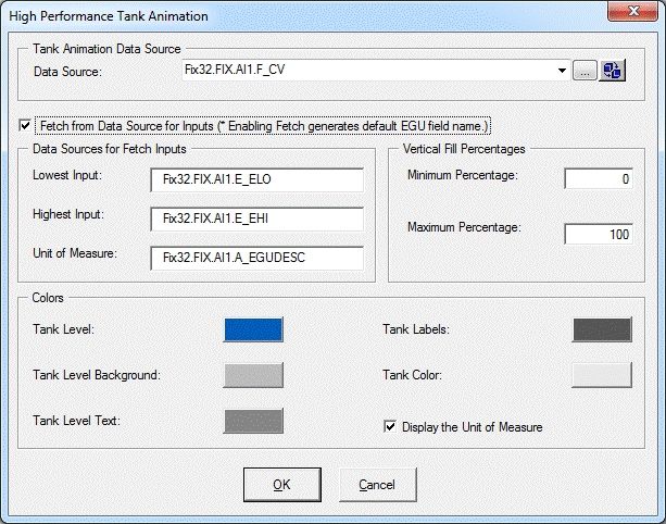
24 © 2020 General Electric Company. All rights reserved.o When this box is checked, it provides dialog boxes for the Data Sources for Fetch Inputs
and generates the default data sources with default EGU fields based on the main data
source you specified. Default data sources for the Lowest Input, Highest Input, and Unit
of Measure can be modified if needed. When you enable this checkbox and specify:
l A data source, then default fields for the data source are used for fetch. If neces-
sary, you can edit the data sources for fetch inputs. For example, the following
screen shows the default data sources with default fields for the Lowest Input,
Highest Input, and Unit of Measure generated from the main data source,
Fix32.FIX.AI1.F_CV.
For example, the following screen shows the default data sources with default
fields for the Lowest Input, Highest Input, and Unit of Measure generated from the
main data source, Fix32.FIX.AI1.F_CV. The Lowest and Highest Input values and
the Unit of Measure will be read from those data sources in run mode.
© 2020 General Electric Company. All rights reserved. 25NOTES:
o If you are using iFIX tag item (A_CV or F_CV syntax) through iFIX’s OPC
server, then the default lowest and highest input datasources and UoM data
source are automatically generated as same as straight iFIX tag syntax.
o If you are using a third party OPC driver, then iFIX does not know the EGU
data source items for the lowest and highest since it is vendor dependent;
therefore, you must specify items for the datasources for Fetch Inputs.
o The Default is the same for the main datasource as you can modify it.
l A tag group as a data source, then the tag group substitution is expected to be
defined with no fields. The Lowest and Highest Input values and the Unit of Meas-
ure are read from the default fields of the tag group symbol. For example, if you
define the tag group as tag1, and the substitution is Fix32.FIX.AI0, then you must
specify @tag1@ or @tag1@.F_CV in the data source. Refer to the Tag Group
Substitution section for more information.
26 © 2020 General Electric Company. All rights reserved.NOTE: Data sources for Fetch Inputs do not support complex mathematical expressions, Picture object
properties, or Global Variables.
l Vertical Fill Percentages - Provides a dialog box for the minimum and maximum percentages to
use for this dynamo.
l Tank Colors - You can accept the default colors or select new colors from the high performance
Color Box. The previous illustration shows the default Tank Level and Tank Label colors.
l A check box allows you to select (or deselect) to display the Unit of Measure in the dynamo.
Tag Group Substitutions
You can use the following table to guide you with using Tag Group substitutions.
Tag Group Tag Group Sub- Data Source Result
Symbol stitution in Dynamo
Fix32.FIX.AI0 l @Sample1@.F_CV OK
Sample1
l @Sample1@
FIX.AI0 l @Sample2@.F_CV OK
Sample2
l @Sample2@
AI0 l @Sample3@.F_CV It works in general, but
l @Sample3@ not supported for this
Sample3 dynamo. A Warning
message will appear in
run mode
Fix32.FIX.AI0.F_CV l @Sample4@ It works in general, but
Sample4 not supported for this
dynamo. A Warning
© 2020 General Electric Company. All rights reserved. 27message will appear in
run mode
High-Performance Tank Animations for Historian (HPTanksAnimHist.fds)
Dynamo Set
The high-performance Tank Animations for Historian dynamo set is designed for Historian data sources
only and includes the following dynamos.
NOTES:
l This dynamo set is designed for Historian data sources, or tag groups with Historian tags.
l A Historical Data Link within this dynamo shows the current value or specified historical data in run
mode, which may not scale with the Lowest and Highest Input values.
l Currently, the dynamos do not support complex mathematical expressions, Picture object properties,
or Global Variables.
Dialog Box
The high-performance Tank Animation for Historian Dynamo dialog box contains the following prop-
erties:
l Tank Animations Data Source - Allows you to specify the data source that animates the Tank
Dynamo. Click the browse button (...) to browse data sources in the Expression Builder. Click
the down button to view the last data sources you used. These dynamos are designed to support
GE Historian data sources only.
l Fetch from Data Source for Inputs - When enabled, lets you specify the data source for the
inputs.
28 © 2020 General Electric Company. All rights reserved.o When this box is not checked, the Lowest Input Value and the Highest Input Value fields
are accessible by the user in the Inputs portion of the dialog box. These fields can be mod-
ified by the user.
o When this box is checked, the fields contain dialog boxes with the data sources for the
Fetch Inputs values in the Tank Properties tab. The Lowest Input Value and Highest Input
Value fields show default data sources of the animation object’s LoInValue and HiInValue
properties.
© 2020 General Electric Company. All rights reserved. 29l Tank Properties Tab - Opens dialog boxes for Inputs or the data sources for Fetched Inputs
based on Fetch from Data Source for Inputs status and other settings for animation, Unit of Meas-
ure, and Colors.
Tank Property Description
Inputs Allow you to enter the lowest and highest input values to use.
Allows you to specify data sources for Lowest and Highest
Inputs.
The default data sources are the animation object’s LoInValue
and HiInValue properties. iFIX reads the EGU (Lo and Hi value)
Fetch from Data Source for Inputs
from Historian and then sets them to those properties in run
mode.
In most cases, you do not need to change them. However, you
can use iFIX tags for a work around if needed.
Provides a dialog box for the minimum and maximum per-
Fill Percentages
centages to use for the TankLevel animation in the dynamo.
30 © 2020 General Electric Company. All rights reserved.Allows you to select (or de-select) to display the Unit of Measure
Units of Measure
in the dynamo and specify strings for the Unit of Measure.
Allows you to accept the default gauge level and label colors or
select new colors from the high performance Color Box. The pre-
Colors
vious illustration shows the default Tank Level and Tank Label
colors.
NOTE: Data sources for Fetch Inputs do not support complex mathematical expressions, Picture object
properties (other than default animation object's LoInValue and HiInValue) or Global Variables
l Historian Properties Tab - Opens dialog boxes to select properties to use with Historian tags.
Historian Properties Description
When the checkbox is selected, a timestamp is
Show Time Stamp with Data shown with the data.
Default = Checked.
© 2020 General Electric Company. All rights reserved. 31Lets you enter the date to start the data collection.
l Fixed Date - Lets you specify a specific date to
start gathering data.
Start Date l Days Before Now - Lets you specify the num-
ber of days before today to start gathering data.
Default: Disabled since the Historical Mode is the Cur-
rent Value.
Lets you enter the time to begin to collect data.
l Fixed Time - Lets you enter a specific time to
start gathering data.
l Lock - Locks the current time, even if you
change the time zone in the Date and Time
Properties dialog box in the Control Panel. This
field is only available when you designate a
Start Time
specific time to start the display using the
Fixed Time field.
l Duration Before Now - Allows you to specify
the hours, minutes, and seconds before now
(current date/time) to start the data collection.
Default: Disabled since the Historical Mode is the Cur-
rent Value.
Allows you to select the time zone for the data.
You can also use the checkbox to adjust the time to
Time Zone Daylight Savings Time.
Default: Disabled since the Historical Mode is the Cur-
rent Value.
Provides a drop-down menu to select the Historian
Historical Mode data mode you want to use.
Default: Current Value
Specifies the duration time in days, hours, minutes,
and seconds.
Duration
Default: Disabled since the Historical Mode is the Cur-
rent Value.
Specifies the update (refresh) rate in hours, minutes,
Update Rate
and seconds.
High-Performance Valve Dynamos (HPValves.fds)
Dynamo Set
The high-performance Valve dynamo set includes the following dynamos.
32 © 2020 General Electric Company. All rights reserved.Dialog Box
The high-performance Valve Dynamo dialog box contains the following properties:
l Valve Data Source - Allows you to enter the data source that animates the Valve Dynamo. Click
the browse button (...) to browse data sources in Expression Builder. Click the down button to
view the last data sources you used. These Dynamos are designed to support iFIX real time
data, OPC, and GE Historian. GE Historian data source is supported for the current value.
NOTE: Currently, this dynamo does not support complex mathematical expressions, Picture
object properties, or Global Variables.
l Valve Values - Allows you to enter the following:
o Valve Closed and Open values - Specify the values for the valve to close or open, and
allows you to accept corresponding default colors or select new colors from the high per-
formance Color Box. The following illustration shows the default colors.
o Tolerance - Specifies the rounding factor to be used for the Valve Closed and Valve Open
values. Typically, iFIX uses this value when comparing a process value to a target value.
If the process value is within the specified tolerance, iFIX assumes the two values are
equal. For example, if the target value is 1.0, the tolerance is 0.1, and the current value of
a data source is 0.8, iFIX does not assume the two values are equal because the data
source is not within the specified tolerance. The value must be within the range 0.9 to 1.1
to equal the target value.
© 2020 General Electric Company. All rights reserved. 33Controlling Data Sources in a Picture by Group Selection GE Web HMI allows you to write to tag values associated with an asset’s properties in the GE Web HMI Asset Model. It is possible to define a group of objects in a picture that can be selected at runtime, res- ulting in a control card appearing in which the operator can write to controllable properties of a given asset. This is accomplished with the IsSelectable property in the exported picture JSON file, which is only exported for iFIX Group objects that have Enable Select enabled in iFIX pictures as shown in the fol- lowing graphic. With traditional iFIX pictures, checking the Enable Select property allows an object to be selected in the Run-time environment. With iFIX pictures that are intended for export to GE Web HMI, checking the Enable Select property of a group designates that group as a "click zone" in that picture. A click zone allows properties of a certain asset to be controlled or modified by writing to the associated iFIX tags. When you click on a selectable group that has an asset associated with it, a control card opens to show the current values for a spe- cified set of properties for that asset. Both controllable and non-controllable properties display, based on the configuration of the properties. (Controllable properties are indicated with a gear icon.) Clicking on the control card changes it to Edit view. Edit view allows you to enter new values for those properties. The new values are written to the iFIX database tags when the Confirm button is selected. For information on automatic click zone binding, refer to the Automatically Binding Child Assets to Click Zones using Group Names section. NOTE: Use the Property Window to view and to edit the Enable Select property. For more information, refer to the Properties Window section in the Writing Scripts ebook. 34 © 2020 General Electric Company. All rights reserved.
Automatically Binding Child Assets to Click Zones using Group Names
 When creating the iFIX picture for a certain asset type, specifying a selectable group’s name in a certain
 way results in the click zone being automatically associated with a child asset without further con-
 figuration once the exported iFIX picture is associated with an asset type.

 In order to take advantage of this automatic click zone binding, the group name must be the same as the
 child asset’s property name in the GE Web HMI Asset Model. Each child asset in the model hierarchy is
 represented as a property of a parent asset. In order for the automatic binding to associate a click zone
 with a certain child asset, the group name must exactly match the name of the desired child asset prop-
 erty and the exported iFIX picture must be associated with the parent asset.

 Example:

 For example, say you have an asset type named StorageTank, which has two child asset properties
 defined in the model, – InletPump and OutflowPump, of asset type Pump. When creating an iFIX picture
 for the StorageTank asset type to use with GE Web HMI, you can automatically enable the control card
 for each of these child assets by:

    1. Creating a selectable group of objects within the iFIX picture for each of the child assets.
    2. Naming these groups InletPump and OutflowPump. These are the child asset property names as
       defined in the asset model, (not the child asset instance names for a certain instance of Stor-
       ageTank).
    3. Exporting the iFIX picture from WorkSpace.
    4. Importing the exported picture to GE Web HMI and associating it with the StorageTank asset
       type (assuming that the asset model has already been created/imported).

 After doing this, navigating to any StorageTank in GE Web HMI at runtime and viewing the HMI display
 allows an operator to click on either of these groups of objects to display the control card for that child
 asset – without the need to navigate to that child asset. This allows control of child assets while in the
 context of a parent asset.

 Rules for Automatic Binding of Group Names

     l   You must name the group the same as the child asset property of an asset type.
     l   Only child or other descendant assets of a given asset type can be bound to a click zone in a pic-
         ture associated with that asset type.
     l   You can access the control card for grandchild assets and below by using double underscores (_
         _) in the group name to separate each asset level. For example, if the above Pump asset type
         had a child asset property named RestrictionValve, a click zone could be auto-bound to this
         grandchild asset from the StorageTank picture by defining a selectable group with the name
         InletPump__RestrictionValve or OutflowPump__RestrictionValve. This shows the control card
         for one of these RestrictionValves, depending upon which name you used.
     l   You can display the control card for the asset type that is associated with the IFIX picture, rather
         than one of its descendants, by naming the selectable group the same as the asset type. In the
         previous example, naming a selectable group StorageTank would result in the click zone dis-
         playing the control card for the StorageTank itself when that group is selected at runtime.
 NOTE: It is not necessary to name the selectable groups in a certain way for them to be able to show the con-
 trol card for an asset. It is only necessary in order to take advantage of the automatic binding feature. If you do
 not name them in this way, the click zones will still be selectable at runtime in GE Web HMI, but will require fur-
 ther configuration in GE Web HMI Administration in order to associate them with the desired assets for control
 at runtime.

© 2020 General Electric Company. All rights reserved.                                                                  35
Referencing a Model Property in an Animation
You can reference a model property within an animation. To reference a model property in an animation,
you must type @ (at sign) at the beginning and at the end of the property name. This allows the
GE Web HMI software to differentiate the property name from ordinary text.
Example:
To enter a reference in an animation to the pump1.speed property in the model:
1. Enter the following in the Fill Expert as the Fill Data Source:
@pump1.speed@
2. Export the picture using the Export Web HMI Picture utility. The following line appears in the
JSON file:
"tag": "@pump1.speed@"
For more information on animations, refer to the Creating Pictures ebook.
Picture Design Tips
Use the following design tips when creating a high-performance graphic:
l When organizing your view of the process, think in terms of a model. Be sure to build GE Web
HMI pictures and tag names from that perspective.
l Use tag group aliases that correspond with a model paradigm that uses one of the following
forms:
- @PropertyName@
- @AssetPropertyName@
- @AssetChildAsset.PropertyName@
l Build your pictures with the Web HMI Toolbox.
l Use the GE Web HMI supported graphics, animations, and dynamos.
l Use the GE Web HMI supported high performance Color Box.
l Minimize client-side scripting; scripts are not exported to Web HMI.
l Create new GE Web HMI iFIX pictures or be prepared to rework existing pictures.
l Enable high performance graphics when using dynamo sets to optimize behavior and to ensure
that all GE Web HMI tools are available.
36 © 2020 General Electric Company. All rights reserved.Publishing and Exporting Pictures to Web HMI
You can use the Picture Publish utility to publish iFIX pictures directly for display in the GE Web HMI.
When a GE Web HMI picture is published, it can be used as a mimic in Web HMI.
You also can use this utility to export iFIX pictures for later display in the GE Web HMI client. When a
GE Web HMI picture is exported, a folder is created in the Program Files (x86)
\GE\iFIX\PIC\WebExport folder. The JSON file and a subfolder for images are saved in this folder. The
image subfolder is only created if the picture contains bitmaps. Next, the folder is zipped and saved to
the WebExport folder along with a log file. The zip file makes it easier to copy the files to the web server,
where it will be extracted and used by the GE Web HMI browser. Log and zip files are created for each
GE Web HMI picture exported.
For more information on how to publish and export pictures, refer to the Publishing iFIX Pictures to Web
HMI and Exporting GE Web HMI Pictures to a Folder sections. For a description of the associated dia-
log box, refer to the Publish to Web HMI Dialog Box section.
Publishing iFIX Pictures to Web HMI
The Picture Publish utility allows you to select GE Web HMI picture files to be published to Web HMI.
Additionally, this utility also exports the pictures files as Web HMI Json files to the default WebExport
folder. For example: C:\Program Files (x86)\GE\iFIX\PIC\WebExport\ (as performed in iFIX 5.9).
To configure the Web HMI Server settings in iFIX:
1. In the iFIX WorkSpace ribbon, select the Home tab, and then select Settings, and then User Prefer-
ences. The User Preferences dialog box appears.
2. Select the Web HMI to open the Web HMI Configuration settings.
3. In the Server Name field, enter the host name of your Web HMI Server.
4. Optionally, change the default port (if another port is needed) and add a user name for logging in.
These fields will auto populate the corresponding fields in the publishing dialog box when you go to
publish your picture(s).
5. Click Test Connection to confirm that you can reach the server.
6. If a trusted connection is required for SSL, select the Required Trusted Connection check box.
7. In the mimic export path, enter a path.
NOTE: If you are exporting files to a remote location, you must use a mapped network drive. For instance,
you cannot export files directly to \\MYServer\Program Files (x86)\GE\iFIX\PIC\ExportFiles\. Instead, map
to that location and use the mapped drive in the export location.
8. Select the Publish to Web HMI check box.
To publish iFIX pictures to Web HMI:
1. In Ribbon view, select the Tools tab and, in the Web HMI group, click on the Publish Picture but-
ton. The Publish Picture dialog box appears.
© 2020 General Electric Company. All rights reserved. 372. Select the Select All check box, or select only the pictures that you want to export.
3. If it is not already pre-populated with a path, in the Export Mimic Path field, choose a folder loc-
ation to which the files are published to or accept the default location. You can either type the loc-
ation into the Export location box, or click the Browse button and select the folder from the
directory tree.
NOTE: If you are exporting files to a remote location, you must use a mapped network drive. For
instance, you cannot export files directly to \\MYServer\Program Files (x86)\GE\iFIX\PIC\ExportFiles\.
Instead, map to that location and use the mapped drive in the export location.
4. If applicable, select the Overwrite Existing Export Files check box.
5. Select the Publish to Web HMI check box.
6. If applicable, select the Overwrite Existing Mimics in Web HMI check box.
7. Select the Publish button.
NOTE: Objects in iFIX pictures that are exported with their Visible property set to False do not display in
Web HMI.
For troubleshooting tips, refer to the Troubleshooting the Export section.
Exporting GE Web HMI Pictures to a Folder
The Publish Picture utility allows you to select the picture files to be exported for use with GE Web HMI.
This export utility is different from the traditional iFIX export utility as it places the GE Web HMI files
(JSON format) in the default \WebExport\ folder.
To export GE Web HMI pictures:
1. In Ribbon view, select the Tools tab and, in the Web HMI group, click on the Publish Picture button.
The Publish to Web HMI dialog box appears.
2. In the Export Mimic Path field, review the folder location to which the files are exported. Accept the
default location, type a new location into the Export Mimic Path field, or click the Browse button and
select the folder from the directory tree.
NOTE: If you are exporting files to a remote location, you must use a mapped network drive. For instance,
you cannot export files directly to \\MYServer\Program Files (x86)\GE\iFIX\PIC\ExportFiles\. Instead, map
to that location and use the mapped drive in the export location.
3. From the list of files that appear in the Mimic Selection area, select the file(s) that you want to export.
l Click the file you want to export. You can hold down the Ctrl or Shiftkey and click additional
files if necessary.
- Or -
l To select all files, click the Select All button. (Click the Deselect All button if you want to clear
all file selections.)
4. If applicable, select the Overwrite Existing Export Files check box.
5. Click the Publish button to export the selected files. A message box indicates the success or errors
associated with the export.
NOTE: Objects in iFIX pictures that are exported with their Visible property set to 'False' do not display in Web
38 © 2020 General Electric Company. All rights reserved.You can also read