CONNECTED ENTRY RUCKUS AND ASSA ABLOY - Configuration & Deployment Guide - Revision 1.0 - Alcadis Support
←
→
Page content transcription
If your browser does not render page correctly, please read the page content below
CONNECTED ENTRY
RUCKUS AND ASSA ABLOY
Configuration & Deployment Guide - Revision 1.0

                                             FEBRUARY 2019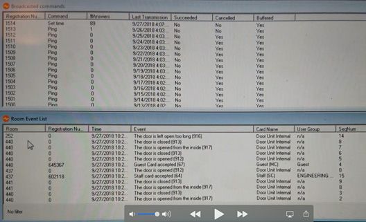
Connected Entry: Ruckus and Assa Abloy
Deployment & Configuration Guide – Revision 1.0

FEBRUARY 2019

TABLE OF CONTENTS
Intended Audience.................................................................................................................................................................................... 4

Introduction............................................................................................................................................................................................... 5

Overview..................................................................................................................................................................................................... 6
       Major Subsystems............................................................................................................................................................................................ 6
       Data Paths.......................................................................................................................................................................................................... 7
       Versions.............................................................................................................................................................................................................. 8

Design & Installation................................................................................................................................................................................. 9
       Wi-Fi Infrastructure, Coverage & AP Placement............................................................................................................................................ 9
       Zigbee Coverage............................................................................................................................................................................................... 9
       Ruckus IoT Ready Infrastructure..................................................................................................................................................................... 9
       Ruckus SmartZone Network Controller......................................................................................................................................................... 9
       Ruckus Access Points (APs)............................................................................................................................................................................ 10
       Ruckus I100 IoT Module................................................................................................................................................................................. 10
       Ruckus IoT Controller..................................................................................................................................................................................... 10
       Assa Abloy Visionline Server.......................................................................................................................................................................... 11
       Creating Zigbee function cards for AAGS locks........................................................................................................................................... 11

Configuration........................................................................................................................................................................................... 12
       Ruckus Access Points...................................................................................................................................................................................... 12
       Ruckus IoT Controller..................................................................................................................................................................................... 13
       Onboarding & Binding Locks......................................................................................................................................................................... 14

Verification & Troubleshooting.............................................................................................................................................................. 19
       Zigbee Sniffer.................................................................................................................................................................................................. 19
       IoT Controller Communications Debugger.................................................................................................................................................. 20
       Visionline Event Logger.................................................................................................................................................................................. 20

© 2019 ARRIS Enterprises LLC. All rights reserved.                                                                                                                                                                            2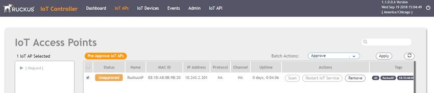
Connected Entry: Ruckus and Assa Abloy
Deployment & Configuration Guide – Revision 1.0

COPYRIGHT NOTICE AND PROPRIETARY INFORMATION
© 2019 ARRIS Enterprises LLC. All rights reserved

No part of this content may be reproduced in any form or by any means or used to make any derivative work (such as translation,
transformation, or adaptation) without written permission from ARRIS International plc and/or its affiliates (“ARRIS”). ARRIS reserves
the right to revise or change this content from time to time without obligation on the part of ARRIS to provide notification of such
revision or change.

Export Restrictions
These products and associated technical data (in print or electronic form) may be subject to export control laws of the United
States of America. It is your responsibility to determine the applicable regulations and to comply with them. The following notice is
applicable for all products or technology subject to export control:

These items are controlled by the U.S. Government and authorized for export only to the country of ultimate destination for use by the
ultimate consignee or end-user(s) herein identified. They may not be resold, transferred, or otherwise disposed of, to any other country or to
any person other than the authorized ultimate consignee or end-user(s), either in their original form or after being incorporated into other
items, without first obtaining approval from the U.S. government or as otherwise authorized by U.S. law and regulations.

Disclaimer
THIS CONTENT AND ASSOCIATED PRODUCTS OR SERVICES (“MATERIALS”), ARE PROVIDED “AS IS” AND WITHOUT WARRANTIES
OF ANY KIND, WHETHER EXPRESS OR IMPLIED. TO THE FULLEST EXTENT PERMISSIBLE PURSUANT TO APPLICABLE LAW, ARRIS
DISCLAIMS ALL WARRANTIES, EXPRESS OR IMPLIED, INCLUDING, BUT NOT LIMITED TO, IMPLIED WARRANTIES OF MERCHANTABILITY
AND FITNESS FOR A PARTICULAR PURPOSE, TITLE, NON-INFRINGEMENT, FREEDOM FROM COMPUTER VIRUS, AND WARRANTIES
ARISING FROM COURSE OF DEALING OR COURSE OF PERFORMANCE. ARRIS does not represent or warrant that the functions
described or contained in the Materials will be uninterrupted or error-free, that defects will be corrected, or are free of viruses or
other harmful components. ARRIS does not make any warranties or representations regarding the use of the Materials in terms of
their completeness, correctness, accuracy, adequacy, usefulness, timeliness, reliability or otherwise. As a condition of your use of the
Materials, you warrant to ARRIS that you will not make use thereof for any purpose that is unlawful or prohibited by their associated
terms of use.

Limitation of Liability
IN NO EVENT SHALL ARRIS, ARRIS AFFILIATES, OR THEIR OFFICERS, DIRECTORS, EMPLOYEES, AGENTS, SUPPLIES, LICENSORS AND
THIRD PARTY PARTNERS, BE LIABLE FOR ANY DIRECT, INDIRECT, SPECIAL, PUNITIVE, INCIDENTAL, EXEMPLARY OR CONSEQUENTIAL
DAMAGES, OR ANY DAMAGES WHATSOEVER, EVEN IF ARRIS HAS BEEN PREVIOUSLY ADVISED OF THE POSSIBILITY OF SUCH
DAMAGES, WHETHER IN AN ACTION UNDER CONTRACT, TORT, OR ANY OTHER THEORY ARISING FROM YOUR ACCESS TO, OR USE
OF, THE MATERIALS. Because some jurisdictions do not allow limitations on how long an implied warranty lasts, or the exclusion or
limitation of liability for consequential or incidental damages, some of the above limitations may not apply to you.

Trademarks
ARRIS, the ARRIS Logo, Ruckus, Ruckus Wireless, Ruckus Networks, Ruckus logo, the Big Dog design, BeamFlex, ChannelFly, EdgeIron,
FastIron, HyperEdge, ICX, IronPoint, OPENG, SmartCell, Unleashed, Xclaim, ZoneFlex are trademarks of ARRIS International plc and/
or its affiliates. Wi-Fi Alliance, Wi-Fi, the Wi-Fi logo, the Wi-Fi CERTIFIED logo, Wi-Fi Protected Access (WPA), the Wi-Fi Protected Setup
logo, and WMM are registered trademarks of Wi-Fi Alliance. Wi-Fi Protected Setup™, Wi-Fi Multimedia™, and WPA2™ are trademarks
of Wi-Fi Alliance. All other trademarks are the property of their respective owners.

© 2019 ARRIS Enterprises LLC. All rights reserved.                                                                                           3
Connected Entry: Ruckus and Assa Abloy
Deployment & Configuration Guide – Revision 1.0

INTENDED AUDIENCE
This document outlines the steps in the deployment and configuration of the Assa Abloy connected smart locks using the Ruckus
Networks wireless infrastructure. The document has been written for use by systems engineers. A background in the Ruckus
wireless infrastructure as well as the Assa Abloy connected locks is recommended.

© 2019 ARRIS Enterprises LLC. All rights reserved.                                                                              4
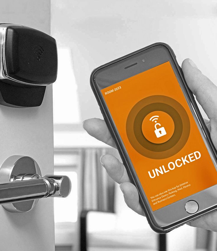
Connected Entry: Ruckus and Assa Abloy
Deployment & Configuration Guide – Revision 1.0

INTRODUCTION
Internet of Things (IoT) deployments are often complex and involve products and services at various layers: devices/endpoints,
network infrastructure, middleware and platform/services. Market complexity at each layer makes deployments risky and requires
extensive integration services. Network silos at each layer necessitate the duplication of equipment and cabling thereby making
deployments expensive. Furthermore, such patched together solutions give rise to security vulnerabilities.

Ruckus + Assa Abloy offer an integrated, unified solution for connected, smart door locks. The solution leverages off the Ruckus
Wireless Wi-Fi infrastructure and Assa Abloy’s leading position in the door-opening marketplace. This integrated approach simplifies
device/endpoint onboarding, establishes uniform security protocols and unifies device/endpoint management and policy setting.

This document provides a step-by-step guide to setting up and configuring a connected lock solution using locks provided by Assa
Abloy and wireless infrastructure provided by Ruckus.

© 2019 ARRIS Enterprises LLC. All rights reserved.                                                                                 5
Connected Entry: Ruckus and Assa Abloy
Deployment & Configuration Guide – Revision 1.0

OVERVIEW
MAJOR SUBSYSTEMS
The Figure below depicts the major system components. Their functionality is summarized in the subsequent table.

                              Wi-Fi Devices

                                                                                                                   Ruckus vSZ

                                 Wi-Fi

                              Access Point                                                                         Ruckus vSZ
                                (Ruckus)

                                                                    Network

                                                                                                                   Ruckus vSZ

                              Zigbee AAGS

                                Smart Lock
                               (ASSA ABLOY)

                                                                                                                                LEGEND

                                                                                                                                     Wi-Fi
                                                                                                                                     IoT

 Subsystem / Component                        Description
 SmartZone Network                           The Ruckus SmartZone Network Controller simplifies the complexity of scaling and managing Ruckus access
 Controller                                  points (APs) and switches. All physical (SZ100 / SZ300) and virtual (VSZ-E / VSZ-H) SmartZone appliances support
                                             network configuration, monitoring, provisioning, discovery, planning, troubleshooting, performance manage-
                                             ment, security and reporting. SmartZone network controllers are essential to managing Ruckus IoT-ready APs.
 Access Points                               The Ruckus family of Wi-Fi APs includes a variety of form factors, performance tiers, and price points. Many Ruck-
                                             us APs can be upgraded with a Ruckus IoT Module to support IoT services such as Zigbee. Specific models that
                                             can be equipped include: H510, R510, T310, E510, R610, T610, R710, R720
 IoT Controller                              The Ruckus IoT Controller is available as a virtual machine and is the management platform for provisioning and
                                             on-boarding Ruckus IoT Modules and also provides connectivity to smart lock management platforms such as
                                             the Assa Abloy Visionline platform.
 Smart Door Lock                             Assa Abloy smart door locks are Zigbee capable and communicate with Zigbee enabled Ruckus APs. Using a
                                             variety of test cards one can activate various door lock functions. Creation of these test cards is discussed later
                                             within this document.
 Visionline Server                           This Assa Abloy Windows based server is the services and management platform for controlling and setting
                                             policy for the smart door locks.
 Wi-Fi Devices                               Wi-Fi devices such as smartphones, tablets and laptops that connect to the Ruckus wireless infrastructure.
 Network                                     The network that provides connectivity between the various components above.

© 2019 ARRIS Enterprises LLC. All rights reserved.                                                                                                                 6
Connected Entry: Ruckus and Assa Abloy
Deployment & Configuration Guide – Revision 1.0

DATA PATHS
Data is sent between an Assa Abloy Smart Door Lock to the Assa Abloy Visionline Server over the Ruckus wireless infrastructure. The
Smart Door Lock connects using Zigbee to a Ruckus I100 IoT Module attached to an upgraded Ruckus IoT-ready AP or to a Ruckus
IoT-embedded AP. The Ruckus AP then forwards the data to the Ruckus IoT Controller which then forwards this to the Visionline
server, thus completing the data path.

Management data is transmitted between the SmartZone Network Controller and Ruckus APs for onboarding and management of
the wireless infrastructure and is not a part of the end-to-end data path.

              Wi-Fi
               IoT
                                                                                       Hotel PMS network

                       Ruckus Virtual SmartZone
                                                                                                                                                   Ruckus IoT Controller

                                                         Wi-Fi Control + Management Plane                     IoT Control + Management Plane

                                                                                                                                                                         Location
                                                                                                                                               Physical   Lock   Light    Based
                                                                                                                                               Security                  Services
                                     Wi-Fi Data Plane:
                                     Local Break-Out

                                                         Wi-Fi Control + Management Plane

                                                                                                           IoT Control + Management Plane
                                                                                                            IoT Control + Management Plane

© 2019 ARRIS Enterprises LLC. All rights reserved.                                                                                                                                  7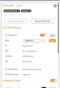
Connected Entry: Ruckus and Assa Abloy
Deployment & Configuration Guide – Revision 1.0

VERSIONS
The following versions/options are required for the integrated setup.

 Component                              Version
 Ruckus SmartZone                       3.6.1.2.10051 or higher. Note that the version must be IoT capable. Higher versions (such as 5.0) may not be IoT
                                        capable.
 Ruckus IoT Controller                  1.0 or higher
 AAGS Visionline Server                 Visionline 1.22.0 or higher. Required Options
                                        •• Online

                                        •• Online advance

                                        •• Online via generic network infrastructure Zigbee

                                        •• # of online rooms

                                        •• Web service for callbacks

                                        •• Web service for checking and confirming alarms

                                        ••   Web service for reading network nodes
                                        ••   Web service for sending open/close commands to doors
 AAGS Smart Door Locks                  3G and/or 4G RFID lock with Zigbee
                                        Lock firmware 3.17.36.1 or higher
                                        Zigbee end node firmware 3.0.60 or higher

© 2019 ARRIS Enterprises LLC. All rights reserved.                                                                                                         8
Connected Entry: Ruckus and Assa Abloy
Deployment & Configuration Guide – Revision 1.0
DESIGN & INSTALLATION
This section addresses the design and installation considerations pertaining to the various system components.
WI-FI INFRASTRUCTURE, COVERAGE & AP PLACEMENT
The design and installation of the Wi-Fi infrastructure (number and placement of APs, switches, power, etc.) is beyond the scope of
this document. There are a number of Design and Best Practice Guides available from Ruckus on how to deploy Wi-Fi in a hospitality
environment.
ZIGBEE COVERAGE
The Zigbee coverage requirement is -65 dBm. In most cases, not all APs need to be equipped with the I100 module to provide
sufficient Zigbee coverage to the all the door locks in a hospitality environment. In a hotel, APs are deployed to provide in room as
well as in-corridor coverage. This typically results in placing APs in the corridors as well as in the room. Equipping the corridor APs
with I100 should provide sufficient Zigbee coverage in most cases.
All hospitality sites are different from a RF Coverage perspective and it is recommended that a site survey be performed with a RF
Sniffer to ensure that sufficient Zigbee coverage will be obtained at the door locks.
RUCKUS IoT READY INFRASTRUCTURE
As described in the Ruckus IoT Suite Getting Started Guide1, this consists of installing the following
1. Ruckus SmartZone Network Controller
2. Ruckus Access Points
3. Ruckus I100 IoT Module on the Ruckus AP
4. Ruckus IoT Controller
RUCKUS SMARTZONE NETWORK CONTROLLER
The Ruckus SmartZone Network Controller is available as either an appliance (SZ-100) or a virtual controller. The virtual controller is
available as an *.ova file and can be installed on the VMWare/ESXi hypervisor. Specifications regarding the minimum requirements
for CPU, Memory, Disk, etc. are provided in the Getting Started Guide2. This guide also contains detailed installation instructions for
various virtualization platforms.
Given below is a brief summary of the relevant steps.
1. Download the relevant image (such as *.ova file) and upload to the Hypervisor
2. Configure the CPU, RAM, Disk, etc. for the image. This is determined by the number of APs, clients, etc. to be supported and is
specified in the Guide mentioned above. Also, delete Network Adapter 2 and 3.
3. Launch the image and wait for it to power up on the hypervisor console
4. Perform the basic configuration:
a. Login in with ‘admin’ for both username and password
b. Enter ‘setup’ command and press enter
c. For example, Enter ‘1’ for Essentials and press enter
d. Enter ‘Y’ and press enter
e. Enter ‘1’ for IPv4 and press enter
f. Enter ‘2’ for DHCP and press enter
g. Note down the assigned IP address to use later for accessing vSZ web UI and enter ‘y’ for yes to and press enter
h. Enter the primary DNS that the IoT Controller uses (refer back to ‘Get Network Info’ command) and press enter
1
Ruckus IOT Suite Getting Started Guide
2
Ruckus SmartZone Getting Started Guide
© 2019 ARRIS Enterprises LLC. All rights reserved. 9Connected Entry: Ruckus and Assa Abloy
Deployment & Configuration Guide – Revision 1.0
i. Enter secondary DNS if applicable, otherwise leave blank and press enter
j. Enter Control NAT IP if applicable, otherwise leave blank and press enter
k. Enter ‘restart network’ to restart changes made and press enter
l. Type ‘setup’ and press enter
m. Type ‘NO’ when asked setup network and press enter
n. Type ‘c” to create new cluster and press enter
o. Enter a cluster name (ie: Vingcard) and press enter
p. Enter a controller description (ie: vrIoT) and press enter
q. Type ‘y’ to confirm settings are correct and press enter
r. Enter a controller blade name and press enter
s. Press enter @ system UTC
t. Press enter @ NTP server
u. Type ‘N’ when asked to convert ZoneDirector APs and press enter
v. Enter a new admin password and press enter, then enter it again and press enter
w. Enter a CLI enable command password and press enter, then enter it again and press enter
x. Wait for setup to complete
5. Access the instance via https using its IP address and port 8443. The username is admin and the password are the one set
above.
RUCKUS ACCESS POINTS (APS)
Deployment of Ruckus APs is beyond the scope of this document. Depending on the AP model number, detailed installation
instructions are available from Ruckus.
After the APs have been installed, one needs to ensure that they have been “discovered” by the Ruckus SmartZone Network
Controller. Once this discovery has taken place, the controller will automatically upgrade the AP firmware.
RUCKUS I100 IoT MODULE
Detailed instructions for installing the I100 IoT module on the AP are available in the I100 Setup Guide.3
RUCKUS IoT CONTROLLER
The Ruckus IoT Controller is a virtual controller that is available as a *.ova file that can be installed on the VMware ESXi hypervisor.
Detailed installation instructions including the CPU, RAM, Disk, etc. requirements are contained in the IoT Controller Installation
Guide.4
Given below is a summary of the relevant steps for installing this on the VMWare ESXi platform.
1. Download the *.ova image and upload to the ESXi server
2. Verify that the instance has 2 vCPUs, 2 GB RAM and 8GB disk
3. Power up the instance and access it via the console. Credentials are admin/admin
4. Enter 1 to get the IP address of the virtual machine
5. Access the instance via a Web browser. Both http and https are supported
6. In the initialization page, select all the services and also specify the FQDN for this instance
7. Confirm the configuration information and click Start
8. The IoT Controller page is now displayed. Credentials are admin/admin
3
Ruckus I100 IoT Module Quick Setup Guide
4
Ruckus IOT Controller, Software Installation Guide
© 2019 ARRIS Enterprises LLC. All rights reserved. 10Connected Entry: Ruckus and Assa Abloy
Deployment & Configuration Guide – Revision 1.0
ASSA ABLOY VISIONLINE SERVER
This is a Windows based server. After installation, its IP Address/FQDN as well as the login credentials should be noted.
CREATING ZIGBEE FUNCTION CARDS FOR AAGS LOCKS
These exercise various door lock functions and are required for the binding process as well as for verification and troubleshooting.
They can be created using the Visionline server as follows:
1. You will need 2 x 4K Mifare keys (Staff keys)
a. Set sub product Zigbee key
b. Start discovery in Zigbee
2. Visionline operator who has access to login and create Zigbee setup cards
3. In the Navigation window to the left, scroll down to SETUP CARDS
4. Select ZIGBEE CONFIGURATION
5. Click the ‘…’ button to select the user the key is being issued for
6. Set the number of days you want this key to be valid for
7. Under type, select SET SUB PRODUCT ZIGBEE
8. Click ‘Make card’ button
9. Repeat steps 3-8 with the exception of step 7, select START DISCOVERY IN ZIGBEE
© 2019 ARRIS Enterprises LLC. All rights reserved. 11Connected Entry: Ruckus and Assa Abloy
Deployment & Configuration Guide – Revision 1.0
CONFIGURATION
This section outlines the configuration steps for each subsystem.
RUCKUS ACCESS POINTS
The access point needs to be provisioned with an IoT controller IP address. This can be done either using DHCP Option 43 or using
AP CLI.
DHCP OPTION
The DHCP server could be run on ICX switch or any server. This section presents an example configuration for ICX switch. Please
note the use of option 43, sub-codes 6 for vSZ controller IP and 21 (hex 15) for the IoT controller IP.
ip dhcp-server pool group1
excluded-address 172.16.101.254
lease 1 0 0
network 172.16.101.0 255.255.255.0
option 3 ip 172.16.101.254
option 6 ip 8.8.8.8
option 43 hex 060e3137322e31362e3230302e323030150e3137322e31362e3230302e313030
deploy
AP CLI
1. Log into the AP via ssh (Terminal on MAC or Putty on a PC)
2. Credentials are those listed in the SmartZone Controller (Access Points->AP->Configure->AP Configuration->AP Admin Logon)
3. Enter the following commands
set IoTg-mqtt-brokerip
set IoTg-mqtt-ssl 1
set IoTg-mqtt-port 8883
set IoTg-enable 1
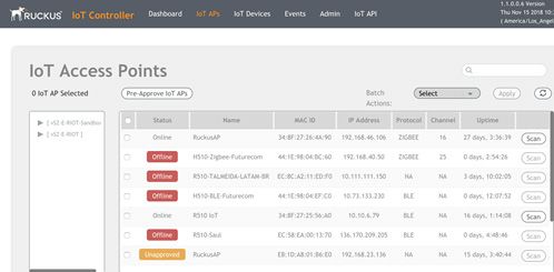
As shown below, the AP will now appear in the IoT Controller “IoT APs” screen. Repeat the above for all APs.
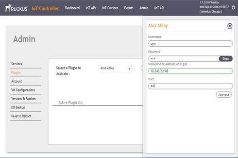
© 2019 ARRIS Enterprises LLC. All rights reserved. 12Connected Entry: Ruckus and Assa Abloy Deployment & Configuration Guide – Revision 1.0 RUCKUS IoT CONTROLLER Assa Abloy Plugin As shown below, the Assa Abloy plugin needs to be activated in the IoT Controller. The IP address and credentials for the Visionline Server are obtained after its installation. © 2019 ARRIS Enterprises LLC. All rights reserved. 13
Connected Entry: Ruckus and Assa Abloy
Deployment & Configuration Guide – Revision 1.0

ONBOARDING & BINDING LOCKS
There are two methods of onboarding and binding the locks: (a) Keycard method and (b) Lock Service 3G method. These are detailed
below.

KeyCard Method (Preferred)
1. On the Ruckus IoT Controller, Go to the IoT APs module
2. All APs previously provisioned should now appear here and awaiting approval
3. Check the box next to the APs, select APPROVE in the batch action drop down, and then click APPLY
4. A pop confirmation of the approval should appear
5. Repeat for each AP

6. Double click on an AP to open the properties
7. Change the MODE to ZIGBEE(AAGS) and click apply
8. A popup confirmation of the changes will appear
9. Once the AP comes back up, it’s ready to bind with a lock
10. Repeat for all APs

© 2019 ARRIS Enterprises LLC. All rights reserved.                                                                            14
Connected Entry: Ruckus and Assa Abloy
Deployment & Configuration Guide – Revision 1.0

11. Click Scan for IoT Devices button and a pop-up window will appear that shows it’s scanning

12. DEVICE SCAN STATUS should pop up indicating IoT is actively scanning
13. Create a Zigbee function keycard. (refer to “Creating Zigbee function cards for AAGS locks” section)
14. A device should now appear in list
15. Enter the preferred name, such as the room number, under the NAME field and click ACCEPT. Once the device has been
    accepted, it will no longer appear in the scan window.
16. Repeat steps 13-15 for any other locks that are to be connected to this AP
17. Once complete, click STOP SCANNIG and repeat all steps above for the next AP

© 2019 ARRIS Enterprises LLC. All rights reserved.                                                                       15
Connected Entry: Ruckus and Assa Abloy Deployment & Configuration Guide – Revision 1.0 18. Go to the IoT DEVICE module at the top of the window 19. All accepted locks should now appear in this list 20. Perform end to end testing to confirm lock events are posting to Visionline and you’re able to send online commands to the lock Lock Service 3G Method This method requires authorized users of Lock Service 3G. 1. On the Ruckus IoT Controller, Go to the IoT APs module 2. All APs previously provisioned should now appear here and awaiting approval 3. Check the box next to the APs, select APPROVE in the batch action drop down, and then click APPLY 4. A pop confirmation of the approval should appear 5. Repeat for each AP © 2019 ARRIS Enterprises LLC. All rights reserved. 16
Connected Entry: Ruckus and Assa Abloy
Deployment & Configuration Guide – Revision 1.0

6. Double click on an AP to open the properties
7. Change the MODE to ZIGBEE(AAGS) and click apply
8. A popup confirmation of the changes will appear
9. Once the AP comes back up, it’s ready to bind with a lock
10. Repeat for all APs

11. Click Scan for IoT Devices button and a pop-up window will appear that shows it’s scanning

12. Connect Service PC to the lock
13. Under CONFIGURE LOCK, select ‘Set sub product Zigbee’ and press ‘Set’
     a. LCU LED should respond with single green flash
14. Under CONFIGURE LOCK, select ‘Start discovery in Zigbee’ and press ‘Set’
     a. LCU LED should respond with a quick green flutter
15. Disconnect Service PC from lock

© 2019 ARRIS Enterprises LLC. All rights reserved.                                               17
Connected Entry: Ruckus and Assa Abloy Deployment & Configuration Guide – Revision 1.0 16. Present a valid guest key to the lock to operate it 17. A device should appear when the IoT AP found the lock 18. Enter the room number/name under the IoT Device Name field 19. Click on the ALLOW 20. This lock should now appear under the IoT Devices module 21. Check Visionline Sysmon to confirm if lock events are populating 22. Perform Visionline any online lock commands to confirm functionality © 2019 ARRIS Enterprises LLC. All rights reserved. 18
Connected Entry: Ruckus and Assa Abloy
Deployment & Configuration Guide – Revision 1.0

VERIFICATION & TROUBLESHOOTING
Overall system operation can be verified by making sure that any action on the lock (such as open/close, use of various test cards,
etc.) is reflected in the Visionline Server. Conversely, any control action (such as door open/close) initiated in the Visionline Server
should be reflected in a corresponding action in the chosen lock.

The following troubleshooting tools can be used to verify communications on the various segments of the Smart Door Lock to
Visionline Server path.

ZIGBEE SNIFFER
Recommended Zigbee Sniffer S/W and hardware modules:

Software:
•• Ubiqua Protocol Analyzer: https://www.ubilogix.com/ubiqua/               (Software license/subscription required)
•• TI SmartRF Packet Sniffer: http://www.ti.com/tool/PACKET-SNIFFER (Free & provides Wireshark integration)

USB Capture Device:
•• TI CC 2531 USB Module: http://www.ti.com/tool/cc2531emk

*Please refer SmartRF documentation for all the supported capture devices

This can be used to examine the door lock to AP communications over Zigbee.

© 2019 ARRIS Enterprises LLC. All rights reserved.                                                                                         19
Connected Entry: Ruckus and Assa Abloy
Deployment & Configuration Guide – Revision 1.0

IoT CONTROLLER COMMUNICATIONS DEBUGGER
Option 8 on the IoT controller invokes the Comm Debugger, which can be used to examine AP to IoT Controller communications.

VISIONLINE EVENT LOGGER
The Event Log on the Visionline Server can be examined to analyze events as seen by the server.

© 2019 ARRIS Enterprises LLC. All rights reserved.                                                                            20
Connected Entry: Ruckus and Assa Abloy
Deployment & Configuration Guide – Revision 1.0

About Ruckus Networks
Ruckus Networks enables organizations of all sizes to deliver great connectivity experiences. Ruckus delivers secure access networks
to delight users while easing the IT burden, affordably. Organizations turn to Ruckus to make their networks simpler to manage and
to better meet their users’ expectations. For more information, visit www.ruckuswireless.com.

© ARRIS Enterprises LLC. All rights reserved. The Ruckus, Ruckus Wireless, Ruckus logo, Big Dog design, BeamFlex, ChannelFly,
Xclaim, ZoneFlex and OPENG trademarks are registered in the U.S. and other countries. Ruckus Networks, MediaFlex, FlexMaster,
ZoneDirector, SpeedFlex, SmartCast, SmartCell, and Dynamic PSK are Ruckus trademarks worldwide. Other names and brands
mentioned in this document or website may be claimed as the property of others.

Ruckus Networks | 350 West Java Drive | Sunnyvale, CA 94089 USA | T: (650) 265-4200 | F: (408) 738-2065 ruckuswireless.com

About ARRIS
ARRIS International plc (NASDAQ: ARRS) is powering a smart, connected world. The company’s leading hardware, software and
services transform the way that people and businesses stay informed, entertained and connected. For more information, visit
www.arris.com.

For the latest ARRIS news:
Check out our blog: ARRIS EVERYWHERE
Follow us on Twitter: @ARRIS

© 2019 ARRIS Enterprises LLC. All rights reserved.
ARRIS, the ARRIS logo, Ruckus, Ruckus Wireless, the Ruckus logo, and the Big Dog design are trademarks of ARRIS International plc and/or its affiliates.
All other trademarks are the property of their respective owners.
www.ruckusnetworks.com | 350 West Java Dr., Sunnyvale, CA 94089 USA                                                                                        19-03-B
You can also read