CONTRIBUTION TO SAFETY OF NAVIGATION BY INTRODUCTION OF NEW TECHNOLOGIES IN FAIRWAY
←
→
Page content transcription
If your browser does not render page correctly, please read the page content below
Journal of Applied Engineering Science Original Scientific Paper
doi:10.5937/jaes18-23624 Paper number: 18(2020)1, 659, 55 - 63
CONTRIBUTION TO SAFETY OF NAVIGATION
BY INTRODUCTION OF NEW TECHNOLOGIES IN FAIRWAY
Pero Vidan, Mirko Čorić, Anita Gudelj, Srđan Vukša*
Faculty of Maritime Studies, University of Split, Split, Croatia
Navigation in archipelagos and shallow waters is considered dangerous. Although islands, reefs, and shallows can
be properly marked by lights and other navigation aids, skippers and other non-professional navigators usually do
not have sufficient experience for safe navigation. Available navigation aids such as radars, Electronic Charts Dis-
play and Information System (ECDIS), and alike are usually expensive for use on small boats and pleasure crafts.
In this paper, the authors propose a new system of identifying navigation marks that would significantly reduce the
possibility of maritime accidents and errors due to a wrong interpretation or invisibility of the mark. The key part of the
new system proposed refers to an innovative method that identifies, delivers, and displays in a user-friendly manner
those navigation marks that are relevant to skippers and other non-professional navigators, depending on their loca-
tion during navigation. The proposed system would be cheaper than the professional SOLAS-approved system, and
available on the web.
Key words: safety, fairway, navigation, navigational marks
INTRODUCTION high for small boats. Therefore, different producers are
trying to replace such devices with new facilities, not SO-
The existing marking system is tailored to professional LAS-approved and with different standards. Such sys-
seafarers and the Convention ships, and has been es- tems are usually based on GPS positioning of ships and
tablished by the International Association of Marine Aids marking of objects on digital charts (plotters, etc.). There
to Navigation and Lighthouse Authorities regulations are no information about navigation marks, or advice,
[1]. Professional seafarers are subject to medical ex- etc. with such devices. In this article, the authors pro-
aminations and certifications required for the renewal of pose a software for easy recognition of navigation marks
seamen’s books and certificates. These have a uniform on the spot and advice for navigation using GPS, and
health check-up system and experience in recognizing tablets or mobile phones. This kind of software should
marks. Boat masters and skippers do not have the nec- make navigation easier and reduce human error, espe-
essary navigation experience, training and licensing pro- cially for non-professional navigator during high season
cedures are less demanding, and they do not fall under period.
the medical examination system [2]. During the high sea-
son, archipelago seas are very popular among tourists. BASIC CONCEPT OF THE METHOD
Therefore, in the waters mentioned, there is the largest
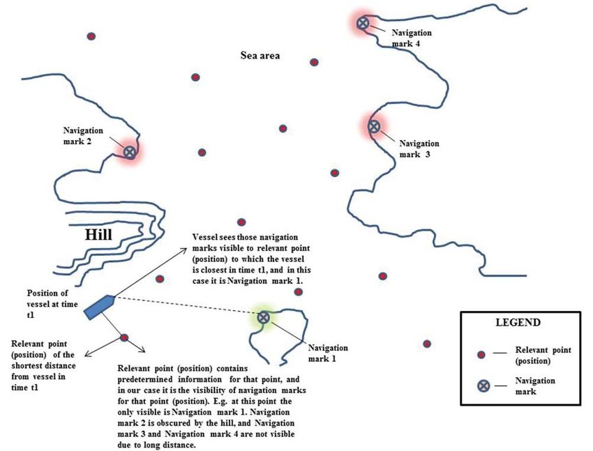
number of smaller (non-Convention) vessels and the For a navigation area, relevant points are determined in
largest number of maritime accidents. advance, i.e. the software stores the Global Positioning
System (GPS) coordinates of relevant points. The num-
All vessels of more than 300 Gross tonnage (GT) and ber of relevant points, their distribution and density can
passenger vessels irrespective of their size are required vary, and the navigation area can be filled by relevant
to be equipped with at least one radar. Electronic Chart points on the basis of different criteria (e.g. even addi-
Display and Information System (ECDIS) is required for tion, addition with regard to the density of maritime traffic
all passenger vessels of more than 500 GT although the in the area, number of navigation marks in the area, in-
administration can lay down stricter requirements for its debtedness of the coast, geography, etc.). For each rele-
own fleet than those of the International Convention for vant point in a navigation area the visibility of navigation
the Safety of Life at Sea (SOLAS) [3, 4]. However, the marks in the vicinity is determined, i.e. navigation marks
majority of smaller vessels used as pleasure crafts are visible for a relevant point are explicitly programmed. A
not legally required to carry any of the above mentioned vessel under way performs in short time intervals the se-
devices [5, 6, 7]. lection in its program of which of the relevant points is
The skippers of smaller leisure crafts usually have insuf- closest to it, and on the navigation display only those
ficient experience. They sometimes sail at night and in navigation marks visible for the relevant point can be
conditions of reduced visibility. In such conditions, the seen. The illustration of the fundamental idea of the
probability of navigation errors due to a wrong interpreta- method is shown in the Figures 1, 2 and 3.
tion of navigation marks is significant. The prices of mod- The proposed method for solving the above mentioned
ern and SOLAS-approved navigational devices might be problem represents a combination of satellite and e-nav-
*svuksa@pfst.hr 55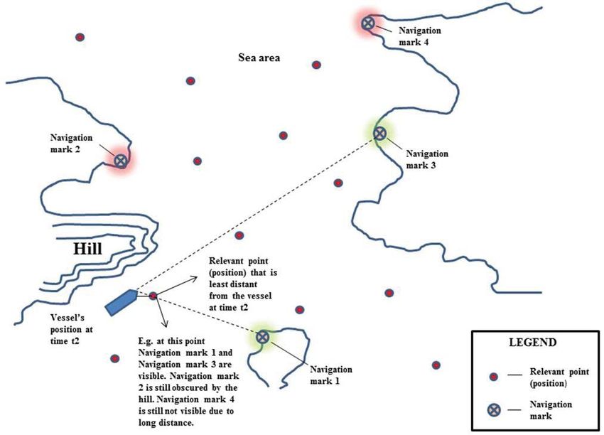
Pero Vidan, et al. - Contribution to safety of navigation by
                                                      introduction of new technologies in fairway

     Figure 1: Vessel at time t1 (Source: Authors)

     Figure 2: Vessel at time t2 (Source: Authors)

56                                  Journal of Applied Engineering Science Vol. 18, No. 1, 2020
                                                                              ISSN 1451-4117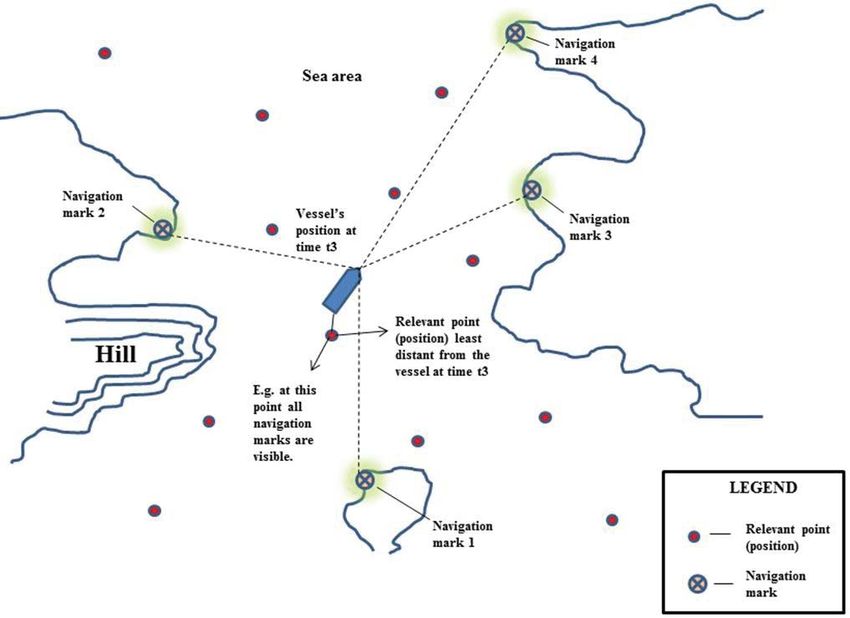
Pero Vidan, et al. - Contribution to safety of navigation by
introduction of new technologies in fairway

                                              Figure 3: Vessel at time t3 (Source: Authors)
igation. Providing that the area has internet access, a               that communicates with the web service while the vessel
reasonably priced and practical solution is proposed in               is under way. Thus, the shipboard application initiates
the form of web service to enable the above mentioned                 the session, i.e. communication with the web service,
method, and user applications (applications used by                   and the session lasts as long as the vessel is under way.
seafarers, e.g. skippers on boats) to communicate with                It is proposed that the user application to be used by
the web service (Figure 4).                                           seafarers on board has a graphical interface with the di-
The approach proposed allows user applications that                   vision into three parts to indicate navigation marks, their
would be used by seafarers to communicate with the                    distances, and bearings of navigation marks relative to
web service to be implemented in different ways. It can               the vessel’s course as proposed on Figure 12 [8]. Also,
be an application started on the mobile phone, tablet,                it is proposed that the method is realised/implemented
computer or any other device (connected to the internet)              as a web service, and available on the internet togeth-
                                                                      er with a database of relevant points. This would mean
                                                                      that the user (shipboard) application would not perform
                                                                      any calculations, but it would have the role of a graphi-
                                                                      cal interface for the display of data related to navigation
                                                                      marks, provided by the web service while under way, and
                                                                      to which the application would communicate in such a
                                                                      way that during the session (navigation) it would transmit
                                                                      to the web service the vessel’s GPS coordinates, while
                                                                      the web service would provide back to the application the
                                                                      data related to the visibility of navigation marks for that
                                                                      particular GPS coordinate.
                                                                      From the fundamental idea of the method and the prob-
                                                                      lem posed (Figure 1, Figure 2 and Figure 3), it is clear
                                                                      that the distances between GPS coordinates of the ves-
                                                                      sel and GPS coordinates of the surrounding points (GPS
                                                                      coordinates of the relevant points and GPS coordinates
                                                                      of navigation marks) are small enough to enable the cur-
                                                                      vature of the Earth to be entirely neglected in the calcu-
                                                                      lation.
                                                                      Therefore, all the laws based on spherical trigonometry
                                                                      (the Haversine formula, Great Circle distance, etc.) can
     Figure 4: The concept of web service and ship's                  be neglected [9, 10], and the problem posed can be ob-
          applications using it (Source: Authors)                     served in 2- dimensional Cartesian coordinate system

Journal of Applied Engineering Science Vol. 18, No. 1, 2020                                                                   57
ISSN 1451-4117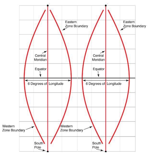
Pero Vidan, et al. - Contribution to safety of navigation by
                                                                                        introduction of new technologies in fairway

[11]. Also, one easily comes to a conclusion that the ac-                                                                        (6)
curacy of the method applied will be proportional to the
                                                              For 2-dimensional space in our case.
number of relevant points.
                                                              The other problem mentioned above is a potentially large
METHOD ANALYSIS AND POSSIBLE ISSUES                           number of relevant points. This problem can be solved
                                                              by the division of the coastal area considered, i.e. of the
The key part of this method is finding the relevant point,    nautical chart, into smaller areas, i.e. sectors. In this way,
i.e. its GPS coordinates closest to the GPS coordinates       a potentially large area with a potentially large number of
of the ship’s position. Thus, it is necessary to compare      relevant points can be divided into a number of smaller
the GPS coordinates of the vessel’s position with a po-       areas with a smaller number of relative relevant points.
tentially large number of the GPS coordinates of the rel-     In that case, the minimum distance would be calculat-
evant points and in doing so, find the one that is closest    ed between the point marking the vessel’s position and
to the GPS coordinates of the vessel’s position. This is      the relevant points of the sector in which the vessel is
done in the way that the Euclidean distance [12, 13] be-      currently found, and all the relevant points of the other
tween the point marking the vessel’s position and the         sectors would be neglected.
relevant points is calculated. The Euclidean distance is
generally described as follows:                               The following analysis gives an insight into the depen-
                                                              dence of the search time for the minimum distance on
The Euclidean distance between the points and is the          the number of relevant points among which the minimum
length of the segment of the line connecting them        .    distance is to be found (Figure 5). It also shows what
In the Cartesian coordinate system,                           happens the search time of the minimum distance when
                                                        (1)   the number of sectors increases in case the above men-
                                                              tioned criterion is applied which proposes the division of
and                                                           the area observed into approximately equal rectangular
                                                        (2)   areas (sectors) with an approximately equal number of
                                                              relevant points across a rectangular area (sector) (Fig-
are two points of the Euclidean n - space, then the dis-
                                                              ure 6). For the following analysis, it is not essential that
tance (d) from p to q, or from q to p is default by the
                                                              the rectangular areas (sectors) be of equal size, but that
Pythagorean Theorem:
                                                              each sector has an approximately equal number of rele-
                                                              vant points. Equal sizes of sectors are recommended for
                                                              simplicity sake.
                                                              From the Figure 5 and the data it is clear that with an
                                                              increase in the number of relevant points, the minimum
                                                        (3)   distance calculation time increases slightly exponential-
                                                              ly. So, in case 8,000 relevant points are used for the area
In our case, the Euclidean distance should be calculated      observed, finding a relevant point closest to the point
for two dimensions only. For p = (p1, p2) and q = (q1, q2)
the two-dimensional Euclidean distance is:
                                                        (4)
which is equivalent to the Pythagorean Theorem.
This part of the method that calculates the distances is
computationally the most demanding due to root calcu-
lation and a potentially large number of relevant points
[13].
The analysis mentioned above suggests that root calcu-
lation during search for the minimum distance between
the point indicating the vessel’s position and the relevant
points is to be avoided due to high processor compu-
tational complexity. In our case, where we actually only
compare the Euclidean distances and search for the
shortest among them (values of lengths are not import-
ant), for optimization reasons it is sufficient enough to
calculate and compare the squares of the Euclidean dis-
tances:

                                                        (5)
                                                              Figure 5: Dependence of minimum distance calculation
For n - dimensional space, i.e.:                                time on the number of 3D points (Source: Authors)

58                                                                    Journal of Applied Engineering Science Vol. 18, No. 1, 2020
                                                                                                                ISSN 1451-4117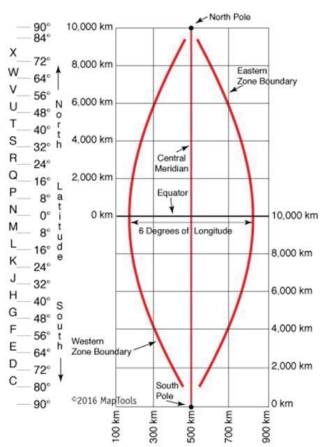
Pero Vidan, et al. - Contribution to safety of navigation by
introduction of new technologies in fairway

                                                               point on the Earth is represented by a segment on the
                                                               horizontal x-axis (“easting“) and segment on the vertical
                                                               y-axis (“northing“). In the calculation, the need for spher-
                                                               ical trigonometry is eliminated, i.e. simple mathematics
                                                               and trigonometry are used just like in the 2D Cartesian
                                                               coordinate system. UTM coordinate system does not
                                                               present negative values, i.e. GPS coordinates of points
                                                               are always represented as positive values.
                                                               UTM coordinate system divides the Earth’s surface into
                                                               60 rectangular UTM zones, and each zone is a large
                                                               rectangle whose two longer sides extend across both
                                                               hemispheres (ellipsoid meridians are ignored), intersect-
                                                               ing the Equator at right angles (Figure 7).
                                                               The entire large rectangle shown in Figure 7 represents
                                                               one UTM zone. Provided we are in the Northern hemi-
                                                               sphere, then the origin can be taken to be the point in
                                                               which the Equator and the upper left outer limit of the
                                                               large rectangle meet. In other words, the Equator is x-ax-
                                                               is, the upper left outer limit of the rectangle y-axis. Pro-
                                                               vided we are in the Southern hemisphere, then the ori-
                                                               gin can be considered to be the point in which the lower
                                                               outer limit of the large rectangle joins the lower left outer
 Figure 6: Dependence of minimum distance calculation          boundary of the rectangle. The actual coordinates of a
     time on the number of sectors (Source: Authors)           point from the zone observed will always be within the
of the vessel’s position will take 640 seconds. These          red ellipsoid from the Figure 7. Therefore, redundancy
minimum distance calculation times can be drastically          occurs on the segments on both axes, and this means
shortened if the above mentioned division of the area          that the actual point from the zone observed will never
observed into sectors is used.                                 be found at the very boundaries of the zone. It is es-
Figure 6 shows the dependence of minimum distance              sential to emphasise that each UTM zone is a particular
calculation time on the number of sectors with the use         coordinate system and there is no mathematical relation
of 8,000 points and approximately even distribution of
points across sectors.
With an increase in the number of sectors, the minimum
distance calculation time is logistically reduced. It is ob-
vious that the maximum reduction of the minimum dis-
tance calculation time (the steepest fall of the curve) is
achieved by introducing only a few sectors. With a further
increase in the number of sectors the calculation time is
further reduced, but less intensively. From the example
it is clear that by entering only 5 sectors the minimum
distance calculation time was reduced by approximately
96%.
The next question posed is the type of coordinate sys-
tem to be used for the display of GPS coordinates of the
points (the point of vessel’s position, relevant points and
the points in which there are navigation marks). As our
problem refers to 2D Cartesian coordinate system, it is
logical to use the projection coordinate system, and the
method has been designed to use Universal Transverse
Mercator (UTM) coordinate system [14, 15]. UTM coor-
dinate system has been chosen because it is simple and
entirely meets the requirements of our method so that
the observed geographical area is reduced to a common
2D Cartesian coordinate system with two axes. UTM co-
ordinate system uses meters as the unit of measurement
(i.e. the need for units of measurement such as degrees,
minutes, seconds is eliminated). The coordinates of a                    Figure 7: Example of UTM zone [16]

Journal of Applied Engineering Science Vol. 18, No. 1, 2020                                                              59
ISSN 1451-4117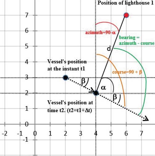
Pero Vidan, et al. - Contribution to safety of navigation by
                                                                                          introduction of new technologies in fairway

with the other coordinate systems, described in detail by
Department of Geography (2018) [15] and Map Tools
(2019) [16].
From the theoretical point of view, it is possible that the
area observed to which we intend to apply the method
extends across two or even more UTM zones. In that
case, we are able to assemble our rectangular areas
(sectors) like “puzzles“, so that they accurately match the
boundaries of UTM zones, not intersecting them. In this
way there is no possibility during the minimum distance
calculation between the relevant points within a rectan-
gular area (sector) for a relevant point to be found in one
UTM zone, and another relevant point in a different UTM
zone. For example, let the small rectangles within UTM            Figure 9: Potential situation in which an error occurs
zone (of the large rectangle) from Figure 7 represent                   in the calculation of the closest relevant
our rectangular areas (sectors). Then, Figure 8 clearly                         point (Source: Authors)
illustrates the concept mentioned by which the possibility
will be eliminated that the rectangular area (sector) inter-
sects UTM zone.
The next problem encountered is the case in which the
vessel is found close to the edge of the sector in which it
plies. Namely, in such a situation there is the possibility
that at a certain point during the calculation of the rele-
vant point which is closest to the vessel at that instant,
the vessel can actually be closer to a relevant point from
the adjacent sector. In that case, due to the way in which
the method described in this paper operates an error will
occur because the closest relevant point of the sector in
which the vessel is found will be considered the closest rel-
evant point, and not the actual closest relevant point from         Figure 10: Proposed concept of reducing the
the adjacent sector. The situation is shown in Figure 9.        probability of error in calculation of the closest relevant
                                                                                 point (Source: Authors)
A satisfactory solution of this problem can be found so
that a larger number of relevant points are located closer      bility of the problem mentioned is reduced. In case the
to the boundaries of the sector. In that case the proba-        problem mentioned still occurs, the significance of the
                                                                error will be minimized as the probability increases (due
                                                                to short distance between the relevant points from one
                                                                and the adjacent sector) for the relevant point at the
                                                                boundary of a sector and the adjacent relevant point at
                                                                the boundary of the adjacent sector to contain the same
                                                                or similar information on the visibility of the navigation
                                                                marks (Figure 10).
                                                                The concept described has the potential to drastically re-
                                                                duce the probability of error, and in case an error still oc-
                                                                curs, it is drastically reduced (due to a reduced distance
                                                                between the relevant points). Naturally, the effectiveness
                                                                of the concept mentioned will increase with an increase
                                                                in the number of relevant points at the edges of a sector
                                                                bordering other sectors, and with the relevant points lo-
                                                                cated closer to the actual edges of the sector.
                                                                It is possible that the vessel is found exactly on the
                                                                boundary between two sectors. That case is simply
                                                                solved in the program so that it is explicitly determined
                                                                for the boundary to which of the two sectors it belongs.
                                                                Due to the concept mentioned from Figure 10 and due
                                                                to short time intervals in which the web service and user
                                                                (shipboard) application communicate, this case does not
 Figure 8: Illustration of a possible sector distribution to    present a problem.
          avoid overlapping of UTM zones [16]

60                                                                      Journal of Applied Engineering Science Vol. 18, No. 1, 2020
                                                                                                                  ISSN 1451-4117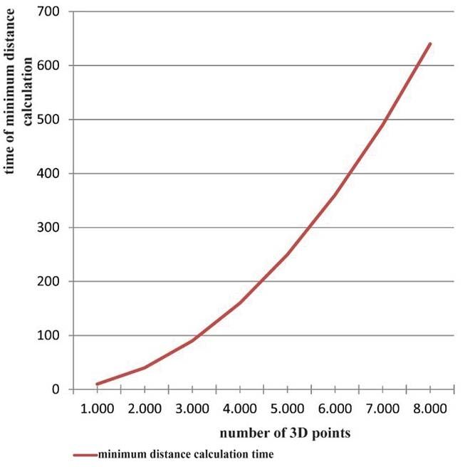
Pero Vidan, et al. - Contribution to safety of navigation by
introduction of new technologies in fairway

It is also possible that the vessel is found at an equal       for “GPS current“ served by the closest relevant point.
distance between two or among more relevant points.            The web service calculates the Euclidean distance (with
The question then is to which of those relevant points the     the calculated root), azimuth and bearing between the
vessel will refer to considering that now there are two or     “GPS current“ and each of the GPS points of the visible
even more closest relevant points. This case is also sim-      navigation marks.
ply solved using the program in the way that one of these      The web service calculates the Euclidean distance (with
relevant points is randomly selected as the point of ref-      the calculated root) d between “GPS current“ and the
erence for the vessel. Like in the paragraph above, due        first GPS point visible to the navigation mark. The web
to the concept mentioned from Figure 10 and short time         service determines in which quadrant there is the first
intervals in which the web service and user (shipboard)        GPS point of a visible navigation mark with regard to
application communicate, this case does not represent          “GPS current“. In other words, it is found out whether the
a problem.                                                     navigation mark is located to the North-East (upper right
A vessel cannot be found at the boundary of two UTM            quadrant of the 2D Cartesian coordinate system), North-
zones due to redundancy on the segments of axis x              West (upper left quadrant of the 2D Cartesian coordinate
(“easting“) and axis y (“northing“), and also due to the       system), South-East (lower right quadrant) or South-
fact that there is no GPS coordinate that simultaneously       West (lower left quadrant) with regard to “GPS current“.
belongs to two UTM zones.                                      Accordingly, the azimuth will be calculated in one of the
                                                               four ways:
ALGORITHM OF THE METHOD
                                                               • 90 degrees - α (upper right quadrant),
The method’s operation principle is described in case          • 90 degrees + α (lower right quadrant),
the method operation logic is found entirely on the web        • 270 degrees + α (upper left quadrant) and
service, and the user (shipboard) application serves only
                                                               • 270 degrees - α (lower left quadrant).
for transmitting the GPS coordinates of the vessel to the
web service and for the display of information on the vis-     α is the angle closed by the line that connects “GPS cur-
ibility of navigation marks that is sent by the web service    rent“ and GPS position of the navigation mark with the
back to the user (shipboard) application. In this case, the    Equator line.
web service is also in charge of calculating the vessel’s      The expression sin is calculated:
course.
                                                                                                                          (7)
An algorithm of the method is presented in steps A, B,
C, D, E and F.
                                                               where                is the difference on “axis y“ between
A) The user/shipboard application transmits two GPS            “GPS current“ and the GPS position of the navigation
coordinates to the web service. One coordinate marks           mark. From the expression mentioned above, it is then
the GPS position of the vessel at the time of transmis-        easy to calculate the angle α. The web service now cal-
sion, and the other marks the previously stored GPS po-        culates the azimuth using one of the four above men-
sition of the vessel from the previous time. Further on,       tioned ways (four different quadrants) to calculate the
these are marked as “GPS current“ and “GPS previous“.          azimuth.
B) The web service searches by the multiple use of “if-        The vessel’s course is calculated using “GPS previ-
else“ expressions to which sector the “GPS current “ re-       ous“ in the same way the azimuth is calculated. In other
ceived by the user/shipboard application belongs.              words, to calculate the azimuth we use distance d, differ-
C) Having detected the sector, the web service search-         ence on “axis y“ between “GPS current“ and the GPS po-
es for the minimum distance between the “GPS current“          sition of the navigation mark, and the above mentioned
and the relevant points from the database (or “cache“          criterion for the calculation of the azimuth, while for the
memory) that belong to this sector. In this search it uses     course the distance will be used between the position
the Euclidean distance for the two dimensions, but does        “GPS current“ and “GPS previous“, difference on “axis
not calculate roots, but only the squares of the Euclidean     y“ between “GPS current“ and “GPS previous“, and the
distances. In that way it finds the shortest distance, i.e.    same criterion based on quadrants that is used in azi-
the closest relevant point.                                    muth calculation (Figure 11).
D) Each relevant point contains a number of navigation         The web service now has at disposal the azimuth and
marks and their GPS coordinates that are visible for that      the vessel’s course, and the bearing is obtained by sub-
navigation mark, and now the web service retrieves from        tracting the course value from the azimuth value. If the
the database (or “cache“ memory) the points of the visi-       difference of azimuth and course is negative, it is the
ble navigation marks for that relevant point. The relevant     matter of port bearing, and if it is positive, it is the matter
point itself after this instant is of no further importance,   of starboard bearing. The bearing cannot be greater than
and does not participate in the further steps in any way.      180 degrees or smaller than -180 degrees. Thus, in case
E) The web service now has at disposal the point “GPS          the bearing value obtained is larger than 180 degrees,
current“ and GPS points of the visible navigation marks        it is necessary to subtract the obtained value from 360
                                                               degrees, so that now it represents a port bearing. In case
Journal of Applied Engineering Science Vol. 18, No. 1, 2020                                                               61
ISSN 1451-4117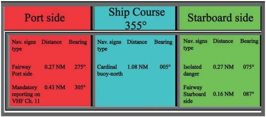
Pero Vidan, et al. - Contribution to safety of navigation by
                                                                                      introduction of new technologies in fairway

                                                                relevant points to increase the method accuracy. For
                                                                the same reason, the existing relevant points can be
                                                                deleted and transferred if the need for this arises.
                                                             • In case new navigation marks occur, the method al-
                                                                lows their easy import.
                                                             • The method can be extended to additional areas
                                                                (addition of new sectors, relevant points).
                                                             • There is the possibility of introducing other ways of
                                                                calculation of the minimum distances between the
                                                                vessel’s position and the positions of relevant points.
                                                             • Relevant points and navigation marks visible for
                                                                each relevant point should be stored by an expert
                                                                (seafarer, navigator).
                                                             • The criteria of number and distribution of the relevant
                                                                points in an area can vary, and some of the criteria
                                                                proposed to be considered when storing the relevant
                                                                points are:
                                                             1. to increase the number of relevant points in places
                                                                where skipper routes are more frequent,
  Figure 11: The concept of calculation of the vessel's      2. to increase the number of relevant points in areas
  course, distance, azimuth, and bearing between the            with a larger number of navigation marks than usual,
       vessel and navigation mark at an instant              3. to increase the number of relevant points at the outer
                   (Source: Authors)                            edges of the sector bordering other sectors, and to
                                                                position the relevant points closer to the edges.
the obtained value of the bearing is smaller than -180 de-
                                                             • The entire program logic of the method is provided
grees, then again from 360 degrees the obtained value
                                                                on the independent web service, and the web ser-
is subtracted, and now it represents a starboard bearing.
                                                                vice can be used by any application and any device.
The web service repeats this step E (except for the
course calculation) for all the points of navigation marks   CONCLUSION
that are visible to the current position of the vessel.
                                                             During the high season period, the number of pleasure
F) The web service sorts navigation marks (i.e. their        crafts and yachts increases. As a result, a higher num-
names) together with the relative distances, azimuths,       ber of accidents occurs. It is almost impossible to control
and bearings relative to the specific vessel in real-time    such a large number of boats by Vessel Traffic Service
communication (from the closest to the farthest naviga-      [17, 18].
tion mark) and transmits to the user (shipboard) applica-    Solutions for fixing position and recognizing navigation
tion which simply displays the information on the screen.    marks with the help of web and internet is available in
The display can be performed as described in Figure 12.      most coastal waters. This solution is relatively cheap and
                                                             available, and of help to navigators, especially those who
FEATURES OF THE METHOD
                                                             navigate for pleasure and in unfamiliar waters.
There are several features of the method de-                 Fixing of position with the help of web and the internet
scribed:                                                     is not professionally or SOLAS-approved. It has errors
• The method can be improved by extension with new           and it depends on the quality of internet communication
                                                             and the quality of hardware. The use of such equipment

                         Figure 12: Example of the receiver displaying ship course 355° [8]

62                                                                   Journal of Applied Engineering Science Vol. 18, No. 1, 2020
                                                                                                               ISSN 1451-4117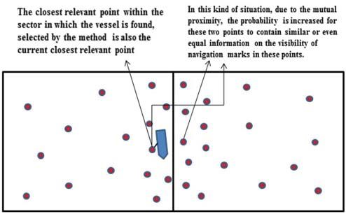
Pero Vidan, et al. - Contribution to safety of navigation by
introduction of new technologies in fairway

might contribute to safe navigation. Therefore, it should      8. Vidan, P. (2010). The model of increasing of safe-
be taken into consideration as a way of reducing errors            ty on inland waterways. Doctoral thesis, Faculty of
in the navigation of pleasure boats.                               Traffic Sciences, Zagreb, 2010.
This is not a method of navigation, but might be a useful      9. Movable Type Scripts. (2019). Calculate distance,
device. Using this new method and relative points could            bearing and more between Latitude/Longitude
be helpful in recognizing navigational marks during nav-           points. https://www.movable-type.co.uk/scripts/lat-
igation. Recognizing sea marks is helpful in the avoid-            long.html. Accessed 12 February 2019.
ance of errors in navigation and use not only GPS data         10. Rosetta Code. (2016). Haversine formula. https://ro-
in fixing the position of the boat.                                settacode.org/wiki/Haversine_formula. Accessed 12
This paper provides detailed descriptions of the novel             February 2019.
method that identifies and presents/displays navigation        11. Math Insight. (2019). Cartesian coordinates. https://
marks to a navigator along with their distances, azimuths          mathinsight.org/cartesian_coordinates. Accessed
and bearings relative to the navigating vessel. An algo-           12 February 2019.
rithm of the method is described in the context of the
                                                               12. NIMA. National Imagery and Mapping Agency.
web solution, but it should be pointed out that the meth-
                                                                   (2000). Department of Defense World Geodetic Sys-
od itself can be implemented locally on a device with its
                                                                   tem 1984: Its Definition and Relationships with Local
own memory, without the presence of the Internet. The
                                                                   Geodetic Systems. http://earth-info.nga.mil/GandG/
analysis of possible method issues is provided from the
                                                                   publications/tr8350.2/wgs84fin.pdf. Accessed 12
theoretical perspective. The implementation of the meth-
                                                                   February 2019.
od in a practical technical/IT solution is planned for our
future consideration.                                          13. Gratneer, C.E. (2017). How to Find Euclidean Distance.
                                                                   https://sciencing.com/euclidean-distance-7829754.
REFERENCES                                                         html. Accessed 12 February 2019.
                                                               14. ArcGIS Resource Center. (2018). Coordinate sys-
1. IALA. International Association of Marine Aids to
                                                                   tems, map projections, and geographic (datum)
   Navigation and Lighthouse Authorities. (2017). IALA
                                                                   transformations. http://resources.esri.com/help/9.3/
   complementary lighthouse use manual. https://www.
                                                                   ArcGISengine/dotnet/89b720a5-7339-44b0-8b58-
   iala-aism.org/product-category/publications/manu-
                                                                   0f5bf2843393.htm. Accessed 12 December 2018.
   als/ Accessed 12 February 2019.
                                                               15. Department of Geography. (2018). The UTM Grid
2. ILO. International Labour Organization. (2015). Sea-
                                                                   and Transverse Mercator Projection. The Pennsyl-
   farer Medical Fitness Standards - Anex I. http://www.
                                                                   vania State University 2018. https://www.maptools.
   lycee-maritime-ciboure.fr/files/Medical_standards_
                                                                   com/tutorials/grid_zone_details. Accessed 12 Feb-
   for_fitness_at_sea.pdf. Accessed 12 February 2019.
                                                                   ruary 2019.
3. IHO. International Hydrographic Organization.
                                                               16. Map Tools. (2019). More details about UTM Grid Zones.
   (2010). Facts about Electronic Charts and Carriage
                                                                   https://www.maptools.com/tutorials/grid_zone_de-
   Requirements. https://iho.int/iho_pubs/standard/S-
                                                                   tails. Accessed 12 December 2018.
   66/S-66_e1.0.0_EN.pdf. Accessed 12 February
   2019.                                                       17. BSU. Federal Bureau of Maritime Casualty Investi-
                                                                   gation. (2009). LT Cortesia Grounding Report. http://
4. IMO. International Maritime Organization. (1995).
                                                                   www.bsu-bund.de/EN. Accessed 12 December
   Resolution A.817(19). Performance standards for
                                                                   2018.
   Electronic Chart Display and Information Systems
   (ECDIS). London: IMO. http://www.imo.org/en/                18. BEA. French Marine Accident Investigation Office.
   KnowledgeCentre/IndexofIMOResolutions/Assem-                    (2010). Sischem Osprey Stranding Report.https://www.
   bly/Documents/A.817%2819%29.pdf. Accessed 12                    google.hr/url?sa=t&rct=j&q=&esrc=s&source=web&c-
   February 2019.                                                  d=1&ved=2ahUKEwil0IvI33gAhWNjqQKHe2XAY-
                                                                   4QFjAAegQIARAC&url=https%3A%2F%2Fwww.nau-
5. SOLAS. International Convention for the Safety of
                                                                   tinst.org%2Fdownload.cfm%3Fdocid%3DF9DA081F-6C1E-40F0
   Life at Sea, 1974. (2014). Chapter 5, Annex 3. Nau-
                                                                   A71F0A89B10F426C&usg=AOvVaw0d8BHGV2inL-
   tical Charts and Publications. Consolidated Edition
                                                                   5CQBiDwvfG2. Accessed 12 December 2018.
   2014.
6. MAIB. Marine Accident Investigation Branch. (2009).
   Pride of Canter-bury Grounding Report. http://www.
   maib.gov.uk.
7. MAIB. Marine Accident Investigation Branch. (2012).                                  Paper submitted: 16.10.2019.
   CSL Thames Grounding Report. http://www.maib.                                         Paper accepted: 31.10.2019.
   gov.uk/ Accessed 12 February 2019.                           This is an open access article distributed under the CC
                                                                                  BY-NC-ND 4.0 terms and conditions.

Journal of Applied Engineering Science Vol. 18, No. 1, 2020                                                           63
ISSN 1451-4117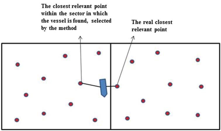
You can also read