CUBEROVER - Astrobotic - Astrobotic Technology
←
→
Page content transcription
If your browser does not render page correctly, please read the page content below
CUBEROVER
                                    PAYLOAD USER’S GUIDE

Publicly available document, please contact Astrobotic Technology for more details.
June 2021 // Version 1.7

                                                                                      © Astrobotic
                                                                    1                 2020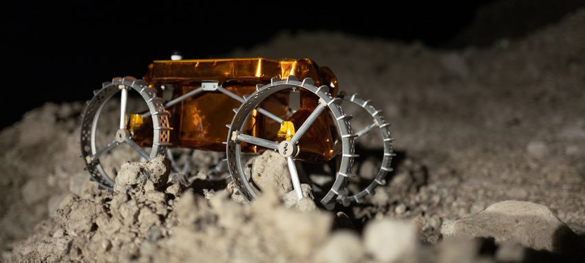
TABLE OF CONTENTS

ABOUT US................................................................................................................................................................................ 3
      WHAT WE DO ...............................................................................................................................................................................4

      ASTROBOTIC’S MOBILITY AS A SERVICE .................................................................................................................................5

      PAYLOAD SERVICES ...................................................................................................................................................................6

      CUBEROVER SERVICES & SUPPORT.........................................................................................................................................7

      CUBEROVER DELIVERY LOCATIONS .........................................................................................................................................8

      ASTROBOTIC LUNAR SERVICES ................................................................................................................................................9

CUBEROVER .......................................................................................................................................................................... 10
      THE CUBEROVER AT A GLANCE ..............................................................................................................................................11

      CUBEROVER BUS SYSTEMS ....................................................................................................................................................12

INTERFACES .......................................................................................................................................................................... 21
      PRESSURE AND HUMIDITY ENVIRONMENT............................................................................................................................22

      PARTICLE & CONTAINMENT ENVIRONMENT ..........................................................................................................................23

      RADIATION ENVIRONMENT ....................................................................................................................................................... 24

      ELECTROMAGNETIC ENVIRONMENT .......................................................................................................................................25

      PAYLOAD TYPES ....................................................................................................................................................................... 26

      PHYSICAL INTERFACES: 2U CUBEROVER ..............................................................................................................................27

MISSION OPERATIONS ........................................................................................................................................................ 35
      THE CUBEROVER MISSION ......................................................................................................................................................36

      CUBEROVER MODES OF OPERATION ..................................................................................................................................... 39

      CUBEROVER USER INTERFACE ...............................................................................................................................................40

      CUBEROVER PAYLOAD INTEGRATION .................................................................................................................................... 41

GLOSSARY ............................................................................................................................................................................. 43
      GLOSSARY OF UNITS................................................................................................................................................................44

      GLOSSARY OF TERMS ..............................................................................................................................................................45

      GLOSSARY OF DOCUMENTATION ........................................................................................................................................... 46

      GLOSSARY OF MILESTONES .................................................................................................................................................. 47

CONTACT US......................................................................................................................................................................... 48

                                                                                                                                                                             © Astrobotic
                                                                                          2                                                                                  2020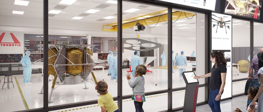
ABOUT US

           © Astrobotic
   3       2020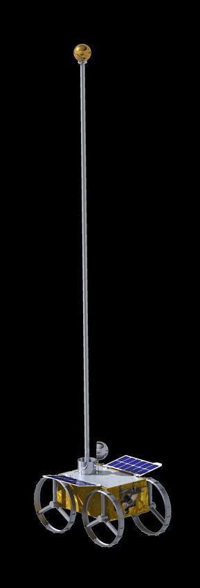
WHAT WE DO
We’re the Moon company and more. We specialize in making space missions feasible and more
affordable for science, exploration, and commerce. And we think the Moon is a great place to start.
As a lunar logistics company, we provide end-to-end delivery services for payloads to the Moon.

    PAYLOAD INTEGRATION                   LUNAR DELIVERY                   PAYLOAD SERVICES
       On each mission, Astrobotic        The Peregrine or Griffin          Peregrine and Griffin provide
     works with payload customers          lander is launched on a         power and data services to
    to integrate their payloads onto       commercially procured       payloads during transit to the Moon
    its lunar landers, Peregrine and     launch vehicle and safely          and on the lunar surface.
          Griffin, and its rovers,      delivers payloads to lunar      CubeRovers and the Polaris rover
         CubeRover and Polaris.         orbit and the lunar surface.   provide power and data services on
                                                                               the lunar surface.

Each payload customer receives comprehensive support from contract signature to end of mission.
The Payload Customer Service Program equips the customer with the latest information on the
mission and facilitates technical exchanges with Astrobotic engineers to ensure payload
compatibility with our lunar products and overall mission success.

                                                                                              © Astrobotic
                                                 4                                            2020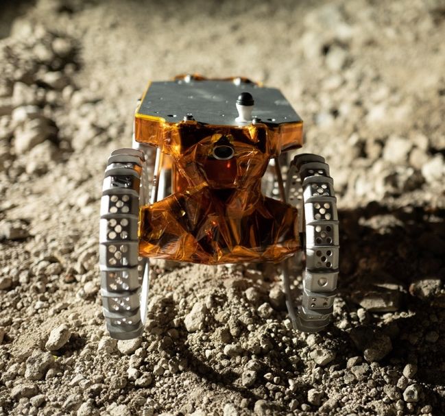
ASTROBOTIC’S MOBILITY AS A SERVICE
Companies, Governments, Universities, Non-Profits, and Individuals can carry and operate
payloads across the Moon’s surface at a price of $4.5M per kilogram of payload.

CubeRovers are designed to be scalable and flexible to meet the demands of payload
customers. This enables payload customers to carry out their own unique surface operations.

CubeRovers are available in the following sizes:

 ROVER CLASS                             2U                         4U               6U

 Rover Mass                           3 - 4 kg                    6 -8 kg         10 - 12 kg

 Payload Capacity                    Up to 2 kg                  Up to 4 kg       Up to 6 kg

For every kilogram of payload,
                                                         POWER: 0.5 W/kg      BANDWIDTH: 10 kbps
CubeRovers provide:

Additional engineering units are available upon request.
To learn more, please contact info-pm@astrobotic.com

                                                                                       © Astrobotic
                                                     5                                 2020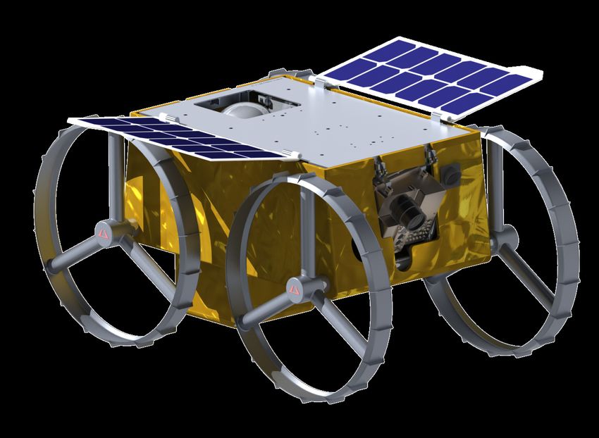
PAYLOAD SERVICES

                 SERVICES AGREEMENT

             1     Following contract signature, the payload customer relates to their
                   payload manager to begin development of a schedule and an Interface
                   Control Document.

                 TECHNICAL SUPPORT
                   Astrobotic supports the payload customer by hosting regular integration
             2     working group meetings, participating in payload design cycle
                   reviews, and facilitating payload testing with simulated rover
                   interfaces. An engineering unit is provided to support payload
                   testing and integration.

                 INTEGRATION
             3     The payload is sent to the Astrobotic integration facility. Astrobotic
                   accepts the payload and integrates it onto the Lander.

                 MISSION
             4     The integrated rover is launched aboard the Lander and commences
                   its mission. The Astrobotic Mission Control Center connects the
                   Payload Customer to their payload for monitoring and operations
                   during flight and on the lunar surface after training from Astrobotic.

                                                                                 © Astrobotic
                                6                                                2020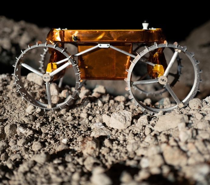
CUBEROVER SERVICES & SUPPORT
CubeRover engineering units perform similar to flight units and are the perfect tool to
practice payload integration and prepare for lunar missions.

Astrobotic is committed to ensuring CubeRover payload customers complete their mission and acquire
meaningful data. In support of this, one CubeRover engineering unit is provided to CubeRover
payload customers prior to flight integration. An engineering unit facilitates payload functional
testing and operations in a relevant environment without damaging flight hardware. Engineering units
are equipped with flight analog hardware and software to simulate expected operational performance.

Additional engineering units are available upon request. To
learn more, please contact info-pm@astrobotic.com

                                                                                              © Astrobotic
                                                     7                                        2020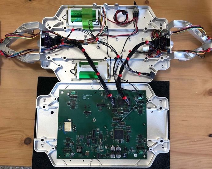
CUBEROVER DELIVERY
LOCATIONS
The CubeRover can safely deliver payloads across the surface at numerous locations on
the moon.

                                             Polar

                                                         M1:
                                                     Lacus Mortis

          Skylights,
        Pits, or Caves

                                     Equatorial
                                                                                 Far Side

                           Craters

                                             Polar

                                                                             © Astrobotic
                                         8                                   2020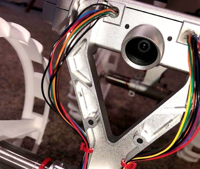
ASTROBOTIC LUNAR SERVICES

Astrobotic is here to support the success of your payload mission. The standard payload interfaces
and services are defined to enable nominal payload missions. This Payload User’s Guide (PUG)
provides an overview of these standard interfaces and services.

Astrobotic can accommodate payloads with needs outside of the standard interfaces and services
at additional cost. Please contact Astrobotic to discuss any nonstandard requests such as custom
interfaces, accommodations of large or unusual geometries, or payload design consulting services,
etc.

The Payload Customer Service Program is a standard service for all payload customers to receive the
tools necessary to design a payload that successfully interfaces with CubeRover.

The following features are included as part of the program:

                             1      Availability for general and technical
                                    inquiries.

                             2      Bi-weekly technical exchanges with Astrobotic mission engineers.

     PAYLOAD
    CUSTOMER                 3      Access to the Astrobotic library of payload design resources and standards.
     SERVICE
    PROGRAM
                             4      Technical feedback through payload milestone design reviews.

                             5      Facilitation of lander-rover-payload interface compatibility
                                    testing.

                                    Provision of a customer-owned engineering unit to support
                             6      payload testing and integration.

NOTE: Access to materials within the Astrobotic library is not always restricted to signed customers. Please contact
Astrobotic for more information on obtaining the latest version of any document referenced within the PUG.

                                                                                                           © Astrobotic
                                                         9                                                 2020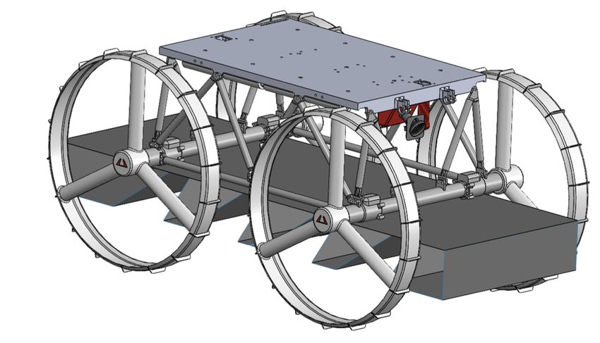
CUBEROVER

            © Astrobotic
   10       2020
THE CUBEROVER AT A GLANCE
The CubeRover delivers payloads across the Moon after deploying to the lunar surface. This
unique offering allows customers to design payloads using standardized CubeRover interfaces.
After payloads are assembled and flight qualified, they are delivered to Astrobotic for integration
and testing onboard the CubeRover.
This is the configuration and specifications of the 2U CubeRover.
SPECIFICATIONS
2U CubeRover Height 40 cm
2U CubeRover Length 50 cm
2U CubeRover Width 28 cm
2U CubeRover Mass up to 5 kg
© Astrobotic
11 2020CUBEROVER BUS SYSTEMS
A core set of systems, known as the bus, define the CubeRover product line.
The spacecraft bus design enables safe payload traversability and operation on the lunar surface.
The bus systems of the CubeRover, listed below, remain consistent throughout the product line
providing confidence in flight-proven design for future missions. These subsystems are described in
greater detail in subsequent pages.
STRUCTURE
TELEOPERATION
POWER
AVIONICS
COMMUNICATIONS
© Astrobotic
12 2020STRUCTURES
The Structure of CubeRovers is stout, stiff, and simple for survivability during
launch and landing.
The CubeRover structure is strong and mass efficient, with the key components being the
chassis frame and radiator surface. The chassis is a machined aluminum design that merges
structural and thermal needs into a low-mass package. The radiator similarly integrates
mounting and thermal grounding needs along with the
deployment interface. The remaining structural components include the solar panel and mounts for the
cameras, actuators, batteries, and payload.
The chassis subassembly serves as the structural mounting interface for the four drive actuators,
cameras, and payload. Mounting configurations may vary depending on payload requirements,
please contact Astrobotic for more information.
The radiator surface serves as the thermal heat sink for all components except the solar panels,
and as the surface for lander fixturing. The integrated avionics unit, cameras, battery packs,
payload, lander electrical interface, and hold-down and release mechanisms are each directly
mounted to the radiator.
The CubeRover driveline is four-wheel drive
and skid steer, unsuspended and driven by
four, flight qualified actuator modules. Each
actuator includes a motor and planetary
gearhead, encoder, wire harnessing, thermal
strapping, and actuator wheel mount. These
actuators bolt directly to forks extending
below the chassis and are thermally grounded
to the radiator. Each output shaft passes
through the fork axle using a combination
bearing and sealed component and mates to
an aluminum wheel hub.
STRUCTURES
Main Structure Material Aluminum
2U CubeRover Payload Mass Capacity Up to 2 kg
2U CubeRover Payload Dimensions 20 x 10 x 10 cm
© Astrobotic
13 2020TELEOPERATION
The CubeRover Teleoperation System allows payload customers to monitor and drive the rover
throughout a user defined mission.
The CubeRover teleoperation system is designed to minimize the risk of mission critical failures
and maximize mission functionality.
The system utilizes a combination of visual odometry and onboard sensors to determine its
position relative to the Peregrine Lander. Absolute localization is conducted by measuring the size
of known components on the lander in an image and then using that information to calculate the
distance of the CubeRover from the lander. Rotation can be inferred similarly by comparing the
relative positions of key features on the lander. During periods of operation when localization
precision is not necessary or when the lander is not visible from the CubeRover, the system will use
a combination of wheel and visual odometry to calculate position relative to the last known starting
point. The current localization software provides a precision of 0.3 cm from 50 m away. The
simulated image at right shows how this software operation is performed.
Within the constraints of safety, the ground control subsystem is designed to achieve the highest
possible speed made good, which is a measure of how much distance the CubeRover will travel
over a given time. The top speed is 10 centimeters per second and the nominal speed is 4
centimeters per second. The speed made good is directly affected by a variety of factors such as
move distance, move planning time, operational time, image size, effective bandwidth, and
transmission delays.
The CubeRover is capable of capturing
and transmitting a variety of images of
varying sizes and compressions. Two
monocular, 16-megapixelcameras are
used for navigation and localization. This
means that for every move the
CubeRover makes, it is capable of
sending multiple driving resolution
images to contextualize the final rover
position and increase operator
awareness of the environment. The
CubeRover is also capable
of cropping images to specific regions,
which allows operators to observe far
away features in high resolution without
The Peregrine Lander is used as a reference to determine the need to transmit a full resolution
relative position. image. The fields of view for each
CubeRover camera are shown below.
© Astrobotic
14 2020Camera vertical and horizontal fields of view.
TELEOPERATIONS
Localized Precision 0.06 millimeters per meter
Nominal Speed 4 cm/s
Camera Front and rear view, 16-megapixel resolution
© Astrobotic
15 2020POWER
The CubeRover is rechargeable, allowing it to generate continuous power
during nominal mission operations.
The CubeRover utilizes pogo pins to receive power from the Peregrine or Griffin Lander in transit to the
Moon. Each CubeRover utilizes a solar array that is mounted to the top of the radiator and deployed
following egress from the lander. Flight heritage solar cells allow the CubeRover to generate
continuous power during roving. This implies that at any given time, regardless of orientation with
respect to the sun, most of the solar panel surface area has a significant view factor to dark space.
The avionics includes a number of DC-to-DC
converters along with circuits to supply the
required power for
the various integrated circuits and
subsystems, as well as manage the batteries
and solar panels. Batteries are monitored and
balanced by a dedicated battery monitor
circuit. The batteries are charged through the
use of the solar panels and a solar charging
circuit.
In addition to battery management, a number
of supply voltages are generated and
regulated on the IAU utilizing a 28Vdc. The
selected DC-DC converters have a variety of
over current and over voltage protections.
POWER
Payload Power 0.5 W per kg continuous, 10 W peak
Payload Power Interface 28 Vdc
CubeRover Battery Composition Lithium-ion
© Astrobotic
16 2020AVIONICS
The CubeRover Avionics perform all command and data handling for the rover.
The avionics system of the CubeRover is primarily comprised of an integrated avionics unit (IAU) that
integrates all power distribution and management, data processing, controls, and communications.
The only electrical components that are not completely integrated onto the board are the cameras,
batteries, solar panels, motors, and a small number of temperature sensors. This approach is taken
to simplify the overall system and enable the success of a small, capable lunar rover.
The integration of the bulk of the avionics system into a single integrated unit has several
advantages. First, it eliminates the need for much of the typical wiring harness. This reduces mass
and volume as well as the number of potential failure points from failed connections. Thermal design
is also simplified by removing the need for thermally strapping many boards to the radiator. The IAU
is simply mounted directly to the radiator allowing for the best possible heat transfer away from the
sensitive circuits. Finally, the high degree of integration reduces the mass and size of the solution by
eliminating the bulk of multiple boards, board mounts, and ancillary components. The IAU is
comprised of a carrier board and processor board and is shown below.
The primary processor is responsible for parsing incoming commands from the ground,
triggering the camera system to take an image, commanding the motor controllers, managing
the storage and retrieval of system data, and managing payload computation commands. This
processor stores and forwards payload data and receives teleoperated commands from ground
control. To ensure robust, safe operation of the IAU, a separate processor is used as a watchdog
monitor. The watchdog monitor has the ability to reset or power cycle the radio and the main
processor if an error is detected. The watchdog monitor also controls the temperature sensors,
heaters, and solar- battery charging circuit.
The primary flight software integrated on the microprocessor
utilizes a lightweight real time operating system. This enables
efficient interleaving of the various tasks being run at any
given time while reducing the risk of one process blocking
another. In addition, the CubeRover utilizes flight heritage
software framework developed by NASA. The primary flight
software receives and interprets all incoming commands from
the ground through the radio. Based on these commands, the
software transitions into one of several modes: roving,
imaging, standby, general operations, or a safe mode. In all
situations, the primary flight software monitors the inertial
sensors, various thermistors, and any error signals or
interrupts from the other integrated circuits on the IAU. In the
case of a fault based on these data, the software can enter
into a safe mode and, as appropriate, take action to safeguard
the payload.
© Astrobotic
17 2020AVIONICS
AVIONICS
Payload I/O Space 20 Pins Available
Data Storage 32 GB Maximum
CubeRover Safety Features EDAC, Software Robustness
© Astrobotic
18 2020COMMUNICATIONS
Astrobotic’s Peregrine and Griffin lander serve as the primary communications
node for CubeRovers relaying data between the CubeRover payload and
Astrobotic’s Mission Control Center.
The CubeRover leverages Astrobotic’s Lander communications network as a relay to receive
commands for the rover and to send telemetry data to the customer’s Payload Mission Control
Center. CubeRover commands are sent to Astrobotic’s Mission Command using TCP/IP through a
private network. Within Astrobotic’s ground systems, the commands for the rover will be sent to
the command processor, where format and data size will be verified before the packet is sent to
the Network Management Center (NMC) using the Payload UDP Packet (PUP) protocol as
referenced in Astrobotic’s Payload ICD. During transit, the ground stations transmit the
commands to the lander through a frequency in the X-band range for uplink and the lander
forwards the commands to the CubeRover through a Serial RS-422 wired connection.
Once deployed the CubeRover uses 2.4 GHz 802.11n Wi-Fi radio using TCP/IP to communicate
with the lander. Customer payloads communicate with the CubeRover using a wired RS-422
connection. This information is then relayed to the Ground Station Network. All CubeRover
downlinked data and uplinked commands are stored in Astrobotic’s telemetry database for
redundancy. All data will be sent through a private network to the customer’s mission control
center.
COMMUNICATION PIPELINE
COMMUNICATIONS
CubeRover Payload Wired Protocol Serial RS-422
CubeRover Payload Wireless Protocol 802.11n Wi-Fi
CubeRover Payload Frequency 2.4 GHz
R/F Communication Capability to Earth 10 kbps per kg
© Astrobotic
19 2020CUSTOM CONFIGURATIONS
Astrobotic has proven flexible and innovative when accommodating nonstandard payload
configurations.
While the base CubeRover product line includes 2 cameras, the 4U
and 6U models are capable of accommodating 4 dual stereo 5
megapixel cameras upon special request. This enables larger FOV
and a wide variety of post mission image processing capabilities.
The unit can supply wireless charging capabilities.
Other nonstandard accommodations made by the rover
development team involves payload geometry widely outside of
the specified payload volume.
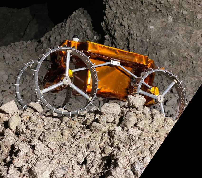
To the upper right you can see a payload that wraps around the axels, narrowly avoiding the FOV of
the 2 front cameras. This design also entails a tailored thermal design.
Another payload involving custom
geometry outside of the payload bay is
shown to the left. You can imagine
even lunar surface operations are
heavily effected and tailored to
accommodate the stringent turning
radius constraints due to the payload.
Another great example of the CubeRover products accommodating
unique payload needs can be seen on the lower right. Internal geometry
can be altered to allow payloads to penetrate through the rover to
protrude far above the rover. Internal hardware is adjusted to make sure
the mission has the greatest chance of successfully capturing the science
it desires.
Finally, to the left we can see
hardware protruding out from
the MLI. This custom imaging
system is stationed outside
of the standard payload
volume into the lunar
environment.
20
© Astrobotic
2020INTERFACES
© Astrobotic
21 2020PRESSURE AND HUMIDITY ENVIRONMENT
PRESSURE ENVIRONMENT
The CubeRover encounters the following approximate pressure environments on a typical
reference mission.
PRE-LAUNCH
101.25 kPa represents the average atmospheric pressure at sea level; the actual value depends on the
respective locations of the integration and launch facilities.
LAUNCH
This is a typical pressure drop curve for launch, which envelopes the pressure drop for all other
mission phases. The pressure drop is expected to surpass –2.5 kPa/s only briefly during transonic
flight as the launch vehicle exceeds the speed of sound and will not exceed -5.0 kPa/s.
REMAINING MISSION
3.2×10⁻⁵ kPa represents the vacuum of the space environment.
HUMIDITY ENVIRONMENT
The CubeRover encounters the following approximate humidity environments while on mission.
LAUNCH
The integration and launch facilities are climate-controlled to 50% ± 15% humidity. The
higher humidity values may occur during transportation and depend on the local climate
of the facilities’ locations.
REMAINING MISSION
The vacuum of the space environment has 0% humidity.
© Astrobotic
22 2020PARTICLE & CONTAINMENT ENVIRONMENT
The CubeRover encounters the following approximate particle and contaminant
environments on a typical reference mission.
PRE-LAUNCH
Planetary Protection regulations govern the Pre-Launch particle and contaminant environment.
Assembly and maintenance of the CubeRover and payloads must occur in a 100k or ISO Class 8
cleanroom. The integration and launch facilities provide suitable cleanrooms for Pre-Launch
activities.
Astrobotic Headquarters and Integration Facility contains two ISO Class 8 cleanrooms for Integration.
CRUISE, LUNAR ORBIT, AND SURFACE
The firing of main and thruster engines of the lander during landing may expel a small amount of
propellant. Following touchdown on the lunar surface, the propulsion system of the lander could
be required to vent excess helium pressurant, which may carry trace amounts of fuel and oxidizer.
These propellant residuals are unlikely to affect payloads; however, payload customers may
design for shielding of sensitive components if so desired.
SURFACE
During the landing procedure, landers will displace an unknown amount of lunar regolith, which
may take several hours or days to fully settle. Lunar regolith is sharp and may cause damage to
sensitive components if mounted outside the standard CubeRover payload envelope. Lunar
regolith is also electrostatically charged, which may cause it to cling to payload surfaces if
mounted outside the standard CubeRover payload envelope. The payload customer is responsible
for identifying at-risk payload systems if mounted outside the standard CubeRover payload
envelope and implementing mitigation strategies such as shielding or deployable dust covers if
necessary.
© Astrobotic
23 2020RADIATION ENVIRONMENT
The CubeRover encounters the following approximate ionizing radiation environments on a typical
reference mission. The Van Allen radiation belts contain energetic protons and electrons that are
trapped in the Earth’s magnetic field and generally follow the magnetic field lines. The overall
structure of the Van Allen belts can be seen from the highly simplified diagram in the figure below.
Low Earth Orbit (ELECTROMAGNETIC ENVIRONMENT
The rover and all payloads must be designed for compliance with MIL-STD-461G for
radiated and conducted emissions. The table below shows the appropriate testing to
perform based on payload type, defined on the following page. Please contact Astrobotic
for additional information or the latest version of the relevant Requirements for the Control
of Electromagnetic Interference Emissions and Susceptibility (MIL-STD-461G) document.
EMI CATEGORY REQUIREMENT APPLICABILITY
Conducted Emissions CE102 Active Payloads
CS101
Conducted CS114 Active Payloads
Susceptibility CS115
CS116
Radiated Emissions RE102 Active Payloads
Radiated Susceptibility RS103 Payloads with Antennas
These tests characterize the interference, susceptibility, and compatibility of the rover and
payloads to ensure appropriate electrical interfacing that does not induce significant
interference, noise, or performance degradation into the integrated system. Additionally,
these tests inform compliance with other external standards and regulations such as Range
Safety. Please contact Astrobotic for the latest version of the relevant Range Safety User
Requirements Manual Volume 3 (AFSCMAN91-710V3) document.
© Astrobotic
25 2020PAYLOAD
TYPES
Astrobotic recognizes four payload types. A payload may be either passive or active as well as
either static or deployable; this results in the four distinct payload types detailed below. The
standard payload interfaces, services, and operations are informed by the payload type.
STATIC DEPLOYABLE
PASSIVE
Static Passive Deployable Passive
• Remains attached to lander • Detaches from lander
• Does not perform mission tasks • Does not perform mission tasks
Example: Memorabilia Example: Surface time capsule
Static Active Deployable Active
ACTIVE
• Remains attached to lander • Detaches from lander
• Performs mission tasks • Performs mission tasks
Example: Sampling tool Example: Science instrument
The CubeRover provides payloads with standard and well-defined interfaces to support their
missions. The following pages outline the standard physical, functional, and ground segment
interfaces for payloads.
The service interfaces, which provide power and data to payloads, vary both by payload type and
mission phase. Service interfaces are described in the Mission Operations section. Astrobotic is able
to accommodate nonstandard interfaces upon request.
Please contact Astrobotic for additional information or the latest version of the Interface Control
Document (ICD), which provides a comprehensive description of the standard interfaces.
© Astrobotic
26 2020PHYSICAL INTERFACES: 2U CUBEROVER
PAYLOAD MECHANICAL INTERFACES AND REQUIREMENTS
CR-ME-001: The payload shall abide by a self-
contained maximum volume constraint defined as
20 cm X 10 cm X 10 cm, as shown in Figure 1. The
payload does not need to fill the maximum volume.
CR-ME-002: The payload shall abide by a
maximum mass constraint defined as 2 kg.
CR-ME-003: The payload shall provide a center of
gravity offset that does not interfere with the
stability of the geometric center of the 20 x 10 x 10
cm available payload envelope by maintaining a
geometric center +/- 1 cm.
CR-ME-004 The payload customer shall provide Figure 1: Payload Size
the principal moments of inertia for the payload,
with an accuracy of at least 10,000 g-mm! computed about the center of gravity of the payload.
CR-ME-005: The payload shall provide up to 6
attachment points, as shown in Figure 2, that will accept a
threaded connection of M5x0.8 to a depth of at least
15mm, designed to withstand installation torque at 8.7
Nm and a clamp load of 8700 N. The payload mass does
not include the mass of the six fasteners.
CR-ME-006: The payload customer shall submit the
following applicable qualification reporting to the rover
team:
• Material Outgassing
• Thermal Operational/Survival
• Sinusoidal vibration
• Random vibration
• Shock
Figure 2: Payload Bolt Pattern (top view)
• Mass, CG & moment of inertia data
• Pressure-venting
CR-ME-007: The payload shall withstand prolonged temperatures of the range -20 to 60°C.
CR-ME-008: The payload external surfaces shall accommodate MLI wrapping by rover team.
CR-ME-009: The payload material selection shall satisfy NASA-EEE-INST-002.
CR-ME-010 : The payload shall not be pressurized, contain any pressurized or sealed compartment,
© Astrobotic
27 2020PHYSICAL INTERFACES: 2U CUBEROVER
and shall not contain any undeclared stored mechanical, chemical, electrical, thermal, or radio-
isotopic energy.
CR-ME-011: The payload shall be radioactively isolated from the spacecraft via multilayer insulation
(MLI) or equivalent.
PAYLOAD ELECTRICAL INTERFACES AND REQUIREMENTS
CR-EL-001: The payload shall include the following electrical connector, as shown in Figure 3.
• Payload-side connector: Samtec P/N ISD2-10-D-S
• Crimp terminal: Samtec P/N CC81L or CC81R
Figure 3: Connector Image & Pin Out
CR-EL-002: The payload shall mount the payload-side electrical connector(s) with sufficient
length to ensure it is within reach of mating connector.
CR-EL-003: The payload shall provide the payload pin configuration as shown in the following
table.
© Astrobotic
28 2020PHYSICAL INTERFACES: 2U CUBEROVER
TABLE 1: CONNECTOR PIN OUT
PIN # FUNCTION ELECTRICAL SPECIFICATION
1 Payload RS-422 Ground GND
2 Payload RS-422 TX+ 0.0 to +0.3 (min) / +6.0 (max) | 0.0 to +2.0 (min) /
+4.0 (min)
3 Payload RS-422 TX- 0.0 to +0.3 (min) / +6.0 (max) | 0.0 to +2.0 (min) /
+4.0 (min)
4 Payload RS-422 RX+ 0.0 to +0.3 (min) / +6.0 (max) | 0.0 to +2.0 (min) /
+4.0 (min)
5 Payload RS-422 RX- 0.0 to +0.3 (min) / +6.0 (max) | 0.0 to +2.0 (min) /
+4.0 (min)
6 Temperature Supply Analog signal 3.3V
7 Temperature Sense Analog signal 1.0 - 3.0V
8 Heater + 28V, 5W
9 Heater - GND
10 Payload Power + 28VDC, 0.5W continuous, 5W max
11 Payload Power - GND
12 Reserved I/O High speed 0 – 3.3V
13 Reserved I/O High speed 0 – 3.3V
14 Reserved I/O High speed 0 – 3.3V
15 Reserved I/O High speed 0 – 3.3V
16 Reserved I/O High speed 0 – 3.3V
17 Reserved I/O High speed 0 – 3.3V
18 Reserved I/O High speed 0 – 3.3V
19 Reserved I/O High speed 0 – 3.3V
20 Reserved I/O High speed 0 – 3.3V
CR-EL-004: The payload shall receive 28VDC and 2 W of electrical power from the lander per the
above table, to heat the payload during transit to the Moon.
© Astrobotic
29 2020PHYSICAL INTERFACES: 2U CUBEROVER
PAYLOAD GROUNDING, BONDING, AND ISOLATION INTERFACE
REQUIREMENTS
CR-GB-001: The payload shall provide one contact point for the internal payload electrical
circuit common ground for the payload structural and conductive elements.
CR-GB-002: The payload shall comply with Class S bonding guidelines, per NASA-STD-4003.
CR-GB-003: The payload shall implement EMI/EMC filters to test against MIL-STD-461.
CR-GB-004: The payload shall submit applicable payload frequency reporting (i.e., rotary, sound,
etc.).
PAYLOAD POWER INTERFACES AND REQUIREMENTS
CR-PR-001: If the payload chooses to exercise the availability of power from the rover, the
payload shall accommodate an operational power of 28VDC+/- 10% voltage output.
CR-PR-002: The payload shall consume an average power of 0.5 W/kg for operation excluding power
for heaters, with a maximum of 10W/kg.
CR-PR-003: The payload shall provide a “stowaway” power service state to comply with an
“off” power mode. This mode shall not receive or deplete power or signal and will be the state
of the payload during launch, lunar ascent/descent, and emergencies.
CR-PR-004: The payload shall provide an “active” power service state to comply with an
“on” power mode. This mode shall allow full functionality of the payload and will be the state
of the payload during operation upon the lunar surface.
CR-PR-005: The payload customer shall submit the following applicable qualification
reporting to the rover team:
• Power states
• State power consumption
• State descriptions
• State anticipated durations
• Payload data transmission details
© Astrobotic
30 2020PHYSICAL INTERFACES: 2U CUBEROVER
PAYLOAD DATA INTERFACES AND REQUIREMENTS
CR-DI-001: The payload customer shall submit the following applicable qualification
reporting to the rover team:
• Mission Success Criteria
• Communication Latency
• Wireless Interface
• Heartbeat
CR-DI-002: If a payload chooses to exercise the use of a data interface with the rover, the payload
shall use a UART RS-422 interface with the following specifications:
• Compatible with the 100 Ohm, 0.5W, termination resistor on the rover Serial RS-422 receiver
circuit.
• Capable of providing a differential signal greater than ± 0.3 V but not exceeding ± 6 V when
connected to CubeRover.
CR-DI-002.02: The payload shall use a minimum standard baud rate of 9,600 bps, with a maximum
of 25Mbps.
CR-DI-003: The payload shall be allocated a maximum of 32 Gb of data storage space.
CR-DI-004: The payload customer shall submit the communication protocol to the CubeRover team:
• Payload data transmission packet details
• Packet integrity method (checksum, parity, etc.)
• Expected data transmission rate
• Hardware handshaking requirements
PAYLOAD TIME SYNCHRONIZATION INTERFACE AND REQUIREMENTS
Astrobotic offers time synchronization for payloads during operations. If the payload would like to
take advantage of the time synchronization feature of the rover, a request may be sent
from the payload to the rover. Timestamps will be relayed to the payload as agreed upon in
the mission success and
operations reports.
CR-TS-001: The payload shall use UTC reference and J2000 format for timekeeping purposes
CR-TS-002: The payload shall maintain time synchronization uncertainty between the
rover and payload, below 20 ms during open communications windows.
CR-TS-003: The payload shall provide time synchronization services only to the rover when in the
ON power service mode.
© Astrobotic
31 2020PHYSICAL INTERFACES: 2U CUBEROVER
PAYLOAD THERMAL INTERFACES AND REQUIREMENTS
The main heat path between the payload and the CubeRover is through the payload bolts that secure
the payload to the rover. The conductance through each bolt is no less than 1.25 K/W (or 0.8 W/K).
Since the payload only receives power from the rover’s power supply and at moderated rate, the
maximum heat output from the payload is known. The CubeRover’s radiator is sized to
accommodate the estimated continuous power consumption of the both the rover and the payload.
The payload may be required to use heaters to maintain its own internal temperature if the payload
power consumption is low for extended periods of time. The following requirements are for the
baseline CubeRover product, and can be tailored alongside thermal redesign efforts as payloads are
assessed on a case-by-case basis. CubeRover products have, and will continue, to make
adjustments to accommodate a variety of payloads.
CR-TI-001: Payload shall accommodate conductance limits through each payload mounting bolt as
no less than 1.25 K/W (or 0.8 W/K).
CR-TI-002: Non-radiating surfaces should be covered with Multi-Layer Insulation (MLI) blankets,
maintaining a surface resistivity of at least 107 Ω/square.
CR-TI-003: Payload Customers shall notify Astrobotic of any nonstandard features, such as
geometry outside of the standard payload bay, for tailoring of thermal design.
EQUIPMENT INTERFACE
CR-EI-001: The rover team shall provide, within the Astrobotic Mission Control Center (AMCC),
one payload console seat.
CR-EI-002: The rover team shall enable the launch of payload customer virtual machine
with installed tools including:
• Google Chrome web browser
• Voice communications application for IP-based voice communication
• Astrobotic-approved software
CR-EI-003: The rover team shall provide a VPN connection with login credentials unique to
payload customer.
CR-EI-004: The payload customer shall maintain and oversee the payload customer Payload
Mission Control Center (PMCC).
CR-EI-005: The payload customer shall operate the PMCC onsite or remotely, via VPN, to the
AMCC payload console seat.
© Astrobotic
32 2020PHYSICAL INTERFACES: 2U CUBEROVER
CR-EI-006: The rover team shall provide approved rover telemetry relative to the mission or
specific to the payload customer PMCC.
CR-EI-007: The rover team shall forward payload telemetry to the payload customer PMCC.
CR-EI-008: The rover team shall forward payload telecommands from the payload customer
PMCC.
CR-EI-009: The payload team shall flag telecommands as hazardous according to categories
defined in the table below.
TABLE 2: ASTROBOTIC HAZARDOUS COMMAND CATEGORIES
CATEGORY DESCRIPTION
Execution of payload Independent Telecommand has
Independent no impact to the rover, e.g., general data logging.
Execution of payload Dependent Telecommand may
Dependent have an impact to the rover, e.g., rover movement.
Execution of payload Hazardous Telecommand has an
Hazardous impact, potentially critical, to the rover, e.g., egress.
© Astrobotic
33 2020PHYSICAL INTERFACES: 2U CUBEROVER
CR-EI-010: The payload shall utilize the telecommand dictionary, compliant with the
defined hazardous command categories.
TABLE 3: PAYLOAD CUSTOMER TELECOMMAND DICTIONARY EXAMPLES
COMMAND NAME DESCRIPTION USAGE HAZARD CATEGORY
During surface checkout
Rover moves forward
phase on the ROVER and
drive_forward a configurable Dependent
following deployment from
distance.
the ROVER
During surface checkout
Rover moves backward
phase on the ROVER and
drive_backward a configurable Dependent
following deployment from
distance.
the ROVER
During surface checkout
Rover sends log data
phase on the ROVER and
log from requested time Independent
following deployment from
interval.
the ROVER
© Astrobotic
34 2020MISSION
© Astrobotic
35 2020THE CUBEROVER MISSION
INTEGRATION
CubeRover integration with Astrobotic’s Peregrine and Griffin landers starts
8 months ahead of expected launch, therefore CubeRover payloads are
requested 8-12 months in advance of launch to integrate the payload with
the CubeRover. CubeRover payloads are to be delivered to the Astrobotic
integration facility where the customer payload will be integrated with the
CubeRover and then the Peregrine or Griffin Lander. After integration,
Astrobotic will perform functional tests to confirm successful integration.
The integrated lander will then be sent to the Kennedy Space Center (KSC)
in Cape Canaveral, FL. Integration with the Launch Vehicle starts 2 months
ahead of expected launch, during which the CubeRover customer payload
is to remain powered off.
LAUNCH
During the prelaunch phase, Astrobotic will evaluate the payload via
environmental, functional, and integration testing for maximum likelihood
of mission success. Hardware will be transported in the OFF state fixed
to the designated rover, eliminating wired, wireless, and time
synchronization capabilities. After launch, cruise, orbit, descent, and
lunar touchdown, the rover will perform preparation activities and
diagnostic checks before deploying to the lunar surface. CubeRover
remains powered down in sleep mode to survive launch conditions.
TRANSIT
CubeRover stays in sleep mode until the
lander begins providing nominal power; this is
to trigger a transition to transit mode.
CubeRover monitors and maintains safe
thermal levels and transmits a heartbeat
through wired communications via the lander
to the CubeRover ground systems.
36
© Astrobotic
2020LANDING
During landing, the CubeRover returns to sleep mode with minimal external
power provided by the lander for thermal management.
DEPLOYMENT
After landing, the Peregrine or Griffin lander provides
power to the CubeRover. The CubeRover then
performs a wired status check and re-establishes
connection with ground systems. On command from
the ground, the CubeRover transitions to mission mode
where it performs a wired status check that includes a
test of the radio and verifies the rover is ready for
deployment. The CubeRover mission team then
activates the release mechanism upon a signal from
Peregrine or Griffin via Astrobotic. Once released, the
CubeRover gently lowers to the ground and comes to
rest.
37
© Astrobotic
2020SURFACE OPERATIONS
Following deployment, the CubeRover enters the Surface Operations phase of the mission. During this
phase, the primary objective is the completion of the customer’s payload objectives for the
mission. Once on the ground, CubeRover performs a Mission Wireless Status Check, transitions
to standby mode, and awaits commands from the ground to begin payload operation. The
CubeRover remains in standby until commanded to take action: either by driving, imaging, collecting
payload data, or performing system maintenance tasks. Customers direct Astrobotic operators to
issue commands using the CubeRover provided user interface that streams live data and images
from the lunar surface for real-time decision making.
The rover is not designed to survive or support operations after the first lunar day. Customers should
plan for services for approximately 8 Earth days after touchdown. Thereafter, the landing site begins
to rotate into lunar twilight and the spacecraft may continue to provide services on an ad hoc basis,
depending on availability, until the onset of lunar night. The rover will deploy as scheduled, no earlier
than 6 hours after touchdown. After the rover is deployed from the lander, wired, wireless, and time
synchronization services will be enabled.
The payload may perform preparation activities and diagnostic checks as a part of its initial payload
operation procedures. Spacecraft to Earth communication windows are nominally scheduled for
cycles of 7 hours “on” and 1 hour “off” for up to 80% uptime during surface operations. The
spacecraft may have to enforce a 24-hour “siesta” with limited power and bandwidth services at
lunar noon in equatorial locations to prevent overheating.
38
© Astrobotic
2020CUBEROVER MODES OF OPERATION
ROVER MODES DESCRIPTION
Ground Only Modes
Service allows access to all rover subsystems and allows for diagnostics and
Service integration with Peregrine Lander.
Transit Modes
Peregrine initiates transit mode by providing power to the rover. The Transit Status Check
Transit evaluates the rover and payload state and determines if it is safe to transition to the heartbeat
Status Check mode. If the check fails, it sends the rover to the Transit Safe mode.
Heartbeat mode is the primary mode of operation during transit. The CubeRover maintains
Heartbeat contact with the ground through a “heartbeat” while monitoring and maintaining a safe internal
temperature.
Transit Safe is one of two safety modes available to the rover. It provides low level debugging
Transit Safe abilities to ground systems while keeping most of the rover powered down.
Mission Modes
Following landing, the rover is commanded from Heartbeat to Mission mode for the first time.
The Mission Wired Status Check performs a diagnostic report on all system functions except
for those restricted by the deployment system. This includes a confirmation that wireless
Mission Wired communications are functioning nominally; following deployment, this will be the only way to
Status Check communicate with the rover. Thermistors will be monitored to confirm that all components
are within operational temperature ranges. The onboard heater can be used to warm the
rover if needed. Finally, this status check also ensures the rover is fully charged and charges
the rover if needed.
Deployment is initiated by Astrobotic Mission Control at the request of the CubeRover team.
Deployment Peregrine provides a power (release) signal to CubeRover, which activates the deployment
mechanism releasing the CubeRover.
Mission Wireless The Mission Wireless Status Check is a general diagnostic check after the rover has
Status Check deployed from the lander.
In Standby mode, the rover waits for a command while transmitting heartbeat and other
Standby telemetry to the ground systems.
When driving or turning, the CubeRover enters Driving mode. The rover remains in Driving
Driving mode until the command is completed. This can occur concurrently with the Imaging and
System Maintenance modes.
When taking a photo, the CubeRover enters Imaging mode which includes the taking,
Imaging cropping, scaling, compression, and transmission of images. This can occur concurrently
with the Driving and System Maintenance modes.
During payload operations the CubeRover diverts its primary power source to customer
Payload supplied payloads, facilitating uninterrupted data flow through the onboard microprocessor
Operations and the payload electronics.
The System Maintenance mode allows for a variety of low impact commands to be executed
System such as resetting specific avionics components or removing images from the system memory.
Maintenance This can occur concurrently with the Driving and Imaging modes.
Mission Safe mode shuts down all non-critical CubeRover components and provides
Mission Safe
low level debugging abilities to ground systems.
© Astrobotic
39 2020CUBEROVER USER INTERFACE
The CubeRover user interface is designed to enable a diverse set of lunar missions by allowing
teams of operators with different roles and responsibilities to collaborate with Astrobotic operators
during the mission. The primary objective of the user interface is to allow simple command sending
and receiving to and from the CubeRover, however, it is also modular to allow operator prioritization
of interface elements that are particularly relevant to their role in ensuring mission success. This
software platform is provided with the CubeRover and can be downloaded to customer computers
for teleoperation at customer facilities via a direct connection to Astrobotic’s Mission Control Center.
Listed below are the key features that have been developed.
MAP
The map is a tool for planning rover missions and
maneuvers. It contextualizes the rover’s position and
orientation relative to the lander and other features
of the lunar surface, the understanding of which is
critical to achieving the scientific objectives of the
mission. It also provides tools for helping plan
complicated but common maneuvers for the rover.
The teleoperated map as seen by the CubeRover Payload Customer.
TELEMETRY VISUALIZATION
The telemetry visualization tool enables users to interpret non-image data from the rover to
monitor for safety and science objectives.
IMAGE VIEWER
The image viewer is the primary tool operators use to understand the environment around
CubeRover and is central to planning the rover’s maneuvers. In addition to displaying images,
the image viewer also now provides basic editing features, a timeline of past images and a
comprehensive feature for naming and tracking points of interest on the lunar surface.
Image Viewer Interface.
40 © Astrobotic
2020CUBEROVER USER INTERFACE
COMMAND LINE
The command line provides a suite of advanced autofill and checking features to ensure that
commands are created quickly and safely by operators.
The command line interface.
41 © Astrobotic
2020CUBEROVER PAYLOAD INTEGRATION
Following contract signature, a payload manager works with the customer to develop
a CubeRover payload schedule and align it to the mission schedule.
The diagram below provides a high-level overview of Astrobotic’s lander and CubeRover schedules.
Astrobotic recognizes that a full set of formal milestone reviews is not necessary for every payload
and works with the customer to appropriately tailor the schedule to the payload type and complexity.
Payload CubeRover CubeRover Lander
ICD CDR SIR SIR
0
24 12 9
Payload CubeRover Lander
Launch
CDR PAR PAR
PAR takes place at the Astrobotic integration facility and is led by the Astrobotic payload
management team; it is mandatory for every payload. The relevant payload deliverables for the
CubeRover PAR must be submitted to Astrobotic prior to the CubeRover PAR at L-10 months. The
physical testing aspect of the PAR can be completed separately prior to Integration such that the
customer can plan to deliver their flight configuration of the payload for acceptance and integration
on the CubeRover between 10 and 8 months prior to launch. Leniency in the deadline is possible for
less complex payloads utilizing fully standard interfaces.
Payload milestones prior to PAR are customer-led at facilities of the customer’s choosing. For major
milestones, as agreed upon during schedule development, an Astrobotic representative must be
included in the review panel. This flexibility in payload schedule is achieved by means of payload
deliverables packages that ensure Astrobotic milestone reviews are informed by the latest payload
specifications.
42 © Astrobotic
2020GLOSSARY
43 © Astrobotic
2020GLOSSARY OF UNITS
UNIT SIGNIFICANCE
bps bits per second [data rate]
dB decibel [sound pressure level referenced to 20x10-6 Pa]
° degree [angle, latitude, longitude]
°C degree Celsius [temperature]
g’s Earth gravitational acceleration [9.81 m/s2]
Hz Hertz [frequency]
kg kilogram [mass]
kPa Kilopascal [pressure]
m meter [length]
N Newton [force]
% percent [part of whole]
rad rad [absorbed radiation dose]
s second [time]
$ United States dollars [currency]
V (dc) Volt (direct current) [voltage]
W Watt [power]
44 © Astrobotic
2020GLOSSARY OF TERMS
TERM SIGNIFICANCE
AMCC Astrobotic Mission Control Center
APR Astrobotic Payload Requirement
EMI Electro-Magnetic Interference
FPGA Field Programmable Gate Array
GNC Guidance, Navigation, and Control
IAU Integrated Avionics Unit
IWG Integration Working Groups
LOI Lunar Orbit Insertion
PMCC Payload Mission Control Center
SEC Standard Electrical Connector
SEU Single Event Upset
UDP/IP User Datagram Protocol / Internet Protocol
TLI Trans-Lunar Injection
VPN Virtual Private Network
45 © Astrobotic
2020GLOSSARY OF DOCUMENTATION
DOCUMENT SIGNIFICANCE
Interface Control Document
ICD The document defines the final lander-payload interfaces and is signed by Astrobotic and the
customer; the IDD is used as a template for this document.
Payload Integration Plan
PIP The document details the Payload Acceptance Review and Integration schedules as well as
verification and validation procedures.
Payload Operations Plan
POP The document details the appropriate handling of the payload system; it is produced in part by
the payload customer and guides Astrobotic operations.
Payload Services Agreement
PSA The document serves as the initial contract between Astrobotic and the payload customer; it defines
programmatic expectations.
Payload User’s Guide
PUG The document provides a high-level overview of the vehicle, mission, as well as the interfaces and
services provided to payloads. (this document)
Statement of Work
SOW The document outlines the responsibilities of Astrobotic and the payload customer; it is part of the
PSA.
46 © Astrobotic
2020GLOSSARY OF MILESTONES
DOCUMENT SIGNIFICANCE
Critical Design Review
CDR The review focuses on the final design of the lander/payload and determines readiness to
proceed with fabrication and testing.
Flight Readiness Review
FRR The review focuses on the integrated launch vehicle and determines readiness to proceed with
launch operations.
Launch Readiness Review
LRR The review focuses on the integrated launch vehicle and determines readiness to fuel the vehicle
and proceed with launch operations.
Operational Readiness Review
ORR
The review focuses on the ground segment and determines end-to-end mission operations
readiness.
Payload Acceptance Review
PAR
The review focuses on the flight-model payload and determines readiness to integrate with the
lander.
Preliminary Design Review
PDR The review focuses on the preliminary design of the lander/payload and determines a feasible
design solution to meet mission requirements exists.
System Integration Review
SIR The review focuses on the flight lander/payload systems and determines readiness to proceed with
assembly and testing.
Test Readiness Review
TRR
The review focuses on the integrated lander and determines readiness to proceed with testing.
47 © Astrobotic
2020You can also read