Custom Fitting a Solution for Custom-Fit Kitchen Appliances - Ansys
←
→
Page content transcription
If your browser does not render page correctly, please read the page content below

FOCU S ON M U LT I PH YS I CS / C F D – D E M COU PLIN G

        Custom Fitting a
          Solution for Custom-Fit
         Kitchen Appliances
        High-end kitchen designs camouflage appliances within their luxurious
        facades, restricting air flow and trapping dust and dirt. Coupled
        CFD–DEM is being used to investigate dirt accumulation.

                                        B
       By Anderson Bortoletto                  uilt-in appliances fill today’s high-end kitchens, in which
       Principal Engineer                      seamless integration with cabinetry can pose technical
       Advanced Product Group                  challenges related to airflow restriction in a machine’s
       Sub-Zero Group Inc.              compartment. This problem is exacerbated by dirt accumulation
       Madison, U.S.A.                  on the condenser (heat exchanger), which can affect appliance
                                        performance.
                                            Experimental evaluation of dirt accumulation on condensers
                                        is time-consuming and expensive. Consequently, Sub-Zero
                                        is coupling computational fluid dynamics (CFD) and discrete
                                        element modeling (DEM) to quickly gain insight on the
                                        mechanisms behind dirt accumulation in an effort to design a
                                        more robust heat exchanger.

20   Ansys Advantage                                                                                         Issue 2 | 2020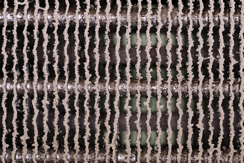
Sub-Zero, which began producing commercial freezer units
three-quarters of a century ago, has re-imagined residential
refrigeration with units built to last 20-plus years. Where the family
kitchen once held a big, bulky appliance, today’s luxury home sports
Compared
smaller, custom-fit modules that locate refrigeration where it makes
the most sense — with options from freezers to ice makers to
wine/beverage centers.
From an engineering standpoint, camouflaged refrigerators to bench-top
wrapped in cabinetry that hinders air flow is an ill-fated scenario for a
component meant to remove heat. Add fiber (pet hair, lint, etc.), dust
component-
and grease accumulation at inaccessible sites, and you’ve created an
ideal recipe for failure.
level testing,
FOULANT AS A RECIPE
overall foulant
One of the first steps in Sub-Zero’s heat exchanger investigation was
figuring out how to define and represent relevant airborne materials,
simulation
collectively referred to as foulant. At the time, the research team had can produce
been using CFD to model simple spherical dust specks within an
air stream, but needed to include non-spherical dirt particles, high- savings of up
aspect-ratio hair, and flexible fibers like cotton. These require DEM
software, which offers accurate particle physics to predict behavior in to 10% of total
a reasonable solve time.
The company’s engineers chose Rocky DEM for its ability to development
accurately model the foulant recipe, speed up computations using
multiple graphics processing units (GPUs), and seamlessly integrate costs — along
with the company’s Ansys multiphysics simulation portfolio. The
team initially used Ansys CFD to model the heat exchanger’s fluid with reduced
flow, which affects overall efficiency. DEM would yield information on
particle deposition, fluid forces acting on particles, such as drag, and time to
adhesion forces, ultimately assessing how the heat exchanger design
affects particle behavior. market.
ONE-WAY STREET?
Originally, the team theorized that the simulation project would
require a two-way coupled CFD–DEM approach, with Ansys
Workbench as the main platform. In theory, dirt accumulation over
time would affect airflow around the heat exchanger, causing foulant
to build up even further and eventually affecting efficiency. If the
change in efficiency was large, performing a two-way analysis would
enable modeling the effect of the foulant on fluid flow and the effect
Air side pressure drop vs dust injection Particle Shedding (Upstream – Downstream) on the Heat Exchanger
0.60 1.00E+05
5.00E+04
0.50
0.00E+00
0.00 2.00 4.00 6.00 8.00 10.00 12.00 14.00 16.00 18.00 20.00
-5.00E+04
0.40
Pressure Drop (mmH2O)
-1.00E+05
Particle Count
-1.50E+05
0.30
-2.00E+05
0.20 -2.50E+05
-3.00E+05
0.10 -3.50E+05
-4.00E+05
0.00 -4.50E+05
0.0 5.0 10.0 15.0 20.0 25.0 30.0 35.0 40.0 45.0 50.0 Particle Size (microns)
Dust injection (g) 5 gm 10 gm 15 gm 20 gm 25 gm 30 gm 35 gm
Figure 1. Experimental results proved that one-way coupling would be sufficient
for accurate simulation results, simplifying the analysis. Left: air-side pressure
drop following dust injection; right: particle shedding over time
© 2020 ANSYS, Inc. Ansys
AnsysAdvantage
Advantage 21
21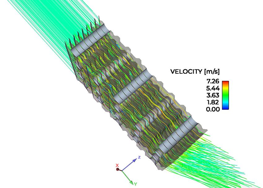
FO CU S ON M U LT I PH YS I CS / C F D – D E M COUPLIN G
of fluid flow on foulant deposition. However, in this case, the effect
of the foulant on fluid flow was small enough to be considered
negligible, as physical experiments showed.
A physical wind-tunnel experiment tested air-side pressure
drop across a heat exchange sample as particles (dust + 5% cotton-
linter fibers) were injected (figure 1). The test also studied the
component’s ability to transfer heat during foulant accumulation
and subsequent particle shedding. Results revealed minimal
changes in pressure drop and heat
transfer. As to particle deposition,
once deposition reaches a specific
value, airflow is sufficient to
shed particles, stopping further
accumulation.
Though experiments are
cumbersome and expensive, they
sometimes provide insight that
can help to simplify a modeling
approach, as testing did in this
case. In a different situation, a
greasy or oily heat exchanger
might exhibit greater particle
adhesion, requiring two-way
Figure 2. Particle movement coupling, thereby lengthening and complicating the analysis
is smooth and uninterrupted process. Bench testing provided the confidence needed to proceed
when there is nothing to with one-way CFD–DEM simulation.
interrupt air flow (top).
Running turbulent dispersion
PHYSICS FOOD FOR THOUGHT
in the Fluent–Rocky simulation
The engineering team leveraged the capabilities of a coupled
ensures naturally occurring
Ansys Fluent–Rocky DEM solution to predict adhesion forces on
vortexes and eddies, which
high-aspect-ratio cotton-linter fibers, modeling electrostatic forces
randomly arise and ebb.
using Rocky’s adhesion model. The Coulomb force — exerted by
stationary objects bearing electric charge on other stationary
objects bearing electric charge — is turned on when particles
move closer than the adhesive distance. The force was set up to
apply to particle–boundary, particle–particle, fiber–fiber and
fiber–dust contact.
Because airflow within the heat exchanger is nonuniform and
particles are small, it was critical to instruct Fluent to run turbulent
dispersion, duplicating real element behavior in the Rocky model
(figure 2). Without it, simulation results produce an average flow
field for every time step instead of naturally occurring turbulence.
In reality, an area that blocks circulation (the wake of a tube, for
example) produces near-zero recirculation velocity; though most
particles are drawn to a higher-velocity region, specks that flow to
this zone will accumulate. Therefore, fluctuating velocity — discrete
piece-wise constant functions of time, computed according to the
local turbulence field (turbulent kinetic energy and dissipation) —
is added to the average fluid velocity: uƒ - ūƒ + úƒ in which total
velocity (uƒ) equals the average velocity from Fluent’s flow field (ūƒ)
plus fluctuating velocity (úƒ), which captures drag force that affects
very tiny particles in the wake of edges.
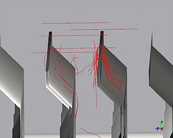
Figure 3. Rocky simulation of Rocky has built-in capabilities to realistically model fibrous
fibers falling, noodle-like, and materials. The software utilizes a sphero-cylinder element joined
catching on the heat exchanger by virtual bonds. Users can adjust flexibility by controlling the
fin’s leading edge. Adjusting Young’s modulus (YM) ratio (figure 3), producing linear and
the YM ratio produced a range angular bond deformation as well as forces and moments on
of bending options, from adjacent elements to resist normal, tangential, bending and
exceptionally flexible to rigid. torsional deformations. Unfortunately, there is negligible literature
22 Ansys Advantage Issue 2 | 2020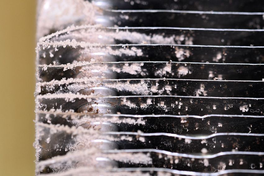
on pet or human hair flexibility parameters,
       so experiments were conducted to calibrate the
       exact YM ratio.
          A CFD hexahedral mesh contained 7.02 million
       flow-aligned cells, a smaller number of elements than
       tetrahedral meshing would require yet fine enough to
       capture a viscous sublayer. It incorporated Y+ for the SST
       turbulence k-w model. The Fluent model was simulated in a
       transient run using air as a compressible fluid phase. Average
       velocity and pressure fields were exported to Rocky for one-way
       coupled simulation (figure 4).
          Rocky DEM computed drag force per particle using Schiller and
       Naumann drag laws for spheres and the Marheineke and Wegener
       drag model for fibers. The simulation included continuous particle
       injection with random orientation.
          Coupled simulation results showed that introducing turbulence
       dispersion to the computation increases the number of collisions
       between particles and walls — and intensifies dust and fiber                 Figure 4. Ansys Fluent velocity
       accumulation. Adhesion force played a major role as well: The higher         simulation results
       the adhesion force, the more mass that is deposited.
          Sub-Zero’s future efforts include validating these simulation
       results with wind-tunnel testing. The process will form the
       framework for modeling particle accumulation on proposed heat
       exchanger concepts. It is critical that the Sub-Zero team gains
       insight about foulant movement and deposition to enable kitchen
       designers to exercise full creativity. For example, a component
       with large leading edges (like current heat exchangers) holds more                    Particulate Modeling
       surface area that can catch dirt. A heat exchanger located at the                     with Rocky DEM webinar
       bottom of the refrigerator captures larger dust particles due to                      ansys.com/DEM
       gravitational effects.
          How does an R&D team develop a better refrigerator design,
       one that is robust to dirt accumulation, based on particle flow
       discoveries?
          Ansys Fluent and Rocky DEM can greatly assist Sub-Zero in this
       effort. This real physics technology provides amazing insight without
       the cost of excessive physical experiments. Compared to bench-
       top component-level testing, overall foulant simulation (once the
       framework is set in place) can produce savings of up to 10% of total
       development costs — along with reduced time to market, since
       results are available in a week, compared to months. The greatest
       savings will be seen on long-term testing programs that deploy
       prototypes in the field.

       A macro view of the non-spherical dirt particles and fibers that foul condensers

© 2020 ANSYS, Inc.                                                                                       Ansys
                                                                                                         AnsysAdvantage
                                                                                                               Advantage   23
                                                                                                                           23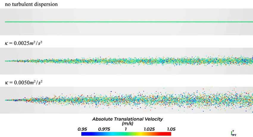
You can also read