D2.1 TAPAS Use Cases Description
←
→
Page content transcription
If your browser does not render page correctly, please read the page content below
EXPLORATORY RESEARCH

D2.1 TAPAS Use Cases
Description
Deliverable ID:           D2.1
Dissemination Level:      PU
Project Acronym:          TAPAS
Grant:                    892358
Call:                     H2020-SESAR-2019-2
Topic:                    SESAR-ER4-01-2019
Consortium Coordinator:   CRIDA
Edition Date:             24 September 2020
Edition:                  00.01.01
Template Edition:         02.00.02
D2.1 TAPAS USE CASES DESCRIPTION

Authoring & Approval

Authors of the document
Name/Beneficiary                    Position/Title                         Date
R. Rodríguez / CRIDA                WP2 Leader                             24/09/2020
A. Olbés / INDRA                    T2.2 Task Leader                       22/07/2020

Reviewers internal to the project
Name/Beneficiary                    Position/Title                         Date
I. Crook / ISA Software             Contributor                            25/08/2020
G. Vouros / UPRC                    Contributor                            27/07/2020
D. Scarlatti / BRTE                 Contributor                            22/07/2020
J.M. Cordero / CRIDA                Project Coordinator                    10/08/2020
E. Iglesias / CRIDA                 Contributor                            10/08/2020
N. Valle / CRIDA                    Contributor                            10/08/2020
G. Andrienko / Fraunhofer           Contributor                            17/08/2020

Approved for submission to the SJU By - Representatives of beneficiaries involved in the project
Name/Beneficiary                    Position/Title                         Date
José Manuel Cordero / CRIDA         Project Coordinator                    24/09/2020
Antonio Gracia / BRTE               Project Member                         Silent Approval
Gennady Andrienko / Fraunhofer      Project Member                         Silent Approval
Hugo Salinas / INDRA                Project Member                         Silent Approval
Ian Crook / ISA                     Project Member                         25/08/2020
George Vouros / UPRC                Project Member                         Silent Approval

Rejected By - Representatives of beneficiaries involved in the project
Name/Beneficiary                    Position/Title                         Date

Document History
Edition               Date           Status               Author             Justification
00.00.01              15/07/2020     Draft                R. Rodríguez       Operational           Cases
                                                                             Description - First Draft
                                                                                                       2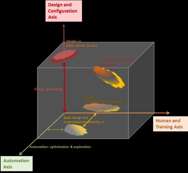
D2.1 TAPAS USE CASES DESCRIPTION

00.00.02           22/07/2020          Draft                 A. Olbés                Technological       Context
                                                                                     Description – First Draft
00.00.03           24/07/2020          Draft                 R. Rodríguez            Integration of        First
                                                                                     Review Comments
00.01.00           11/08/2020          Final                 R. Rodríguez            Integration  of   Final
                                                                                     Review Comments for
                                                                                     approval and submission
                                                                                     to SJU
00.01.01           24/09/2020          Final                 R. Rodríguez            Integration of SJU review
                                                                                     comments
Copyright Statement
© – 2020 – TAPAS Consortium. All rights reserved. Licensed to the SJU under conditions.

                                                                                                               3
D2.1 TAPAS USE CASES DESCRIPTION
TAPAS
TOWARDS AN AUTOMATED AND EXPLAINABLE ATM SYSTEM
This document is part of a project that has received funding from the SESAR Joint Undertaking under
grant agreement No 892358 under European Union’s Horizon 2020 research and innovation
programme.
Abstract
This document describes in detail the use cases to be developed under TAPAS project: (a) from the
operational point of view; and (b) from the technological perspective. It also contains the operational
context description in which TAPAS use cases are to be developed.
In particular, the following use cases are described:
• Conflict Detection and Resolution (CDR), during the tactical phase at the Executive Controller
Controller Working Position,
• Conflict Detection and Resolution (CDR), during the tactical phase at the Planner Controller
Controller Working Position, and
• Air Traffic Flow and Capacity Management (ATFCM), at pre-tactical phase.
4D2.1 TAPAS USE CASES DESCRIPTION
Table of Contents
Abstract ................................................................................................................................... 4
1 Executive Summary .................................................................................................... 7
2 Introduction ............................................................................................................... 8
2.1 Purpose of the document............................................................................................... 8
2.2 Intended Readership ..................................................................................................... 8
2.3 Document Structure ...................................................................................................... 8
2.4 Terminology and Acronyms ........................................................................................... 9
3 TAPAS Operational Context ...................................................................................... 11
3.1 General Overview. Air Navigation Services ................................................................... 11
3.2 Operational Environment ............................................................................................ 12
3.2.1 Transversal Topics ........................................................................................................................... 12
3.2.1.1 Trajectory Based Operations .................................................................................................. 12
3.2.1.2 Free-Route Operations ........................................................................................................... 12
3.2.2 Dynamic Airspace Configuration Concept ....................................................................................... 13
3.2.3 Flight Centric ATC Concept .............................................................................................................. 15
4 TAPAS Operational Use Cases Description ................................................................ 18
4.1 ATFCM Use Case .......................................................................................................... 18
4.1.1 Definitions ....................................................................................................................................... 18
4.1.2 Scope ............................................................................................................................................... 19
4.1.3 Actors .............................................................................................................................................. 19
4.1.3.1 Primary Actors ........................................................................................................................ 19
4.1.3.2 Supporting Actors ................................................................................................................... 19
4.1.4 Preconditions .................................................................................................................................. 19
4.1.5 Post conditions ................................................................................................................................ 19
4.1.6 Success end state ............................................................................................................................ 19
4.1.7 Failure end state.............................................................................................................................. 19
4.1.8 Trigger ............................................................................................................................................. 19
4.1.9 Use Case Flow ................................................................................................................................. 20
4.1.9.1 Main flow................................................................................................................................ 20
4.1.10 Failure flows ................................................................................................................................ 22
4.1.11 Technological Context................................................................................................................. 22
4.2 CDR Use Case (Planning Separation Assurance) ............................................................ 26
4.2.1 Scope ............................................................................................................................................... 26
4.2.2 Actors .............................................................................................................................................. 26
4.2.2.1 Primary Actors ........................................................................................................................ 26
4.2.2.2 Supporting Actors ................................................................................................................... 26
4.2.3 Preconditions .................................................................................................................................. 26
4.2.4 Post conditions ................................................................................................................................ 26
4.2.5 Success end state ............................................................................................................................ 26
4.2.6 Failure end state.............................................................................................................................. 26
4.2.7 Trigger ............................................................................................................................................. 26
4.2.8 Use Case Flow ................................................................................................................................. 26
5D2.1 TAPAS USE CASES DESCRIPTION
4.2.8.1 Main flow................................................................................................................................ 26
4.2.9 Failure flows .................................................................................................................................... 28
4.2.10 Technological Context................................................................................................................. 28
4.2.10.1 First approach: to create CDR tools properly managing this uncertainty .............................. 29
4.2.10.2 Second approach: To minimise the uncertainty of the trajectory ......................................... 30
4.3 CDR Use Case (Tactical Separation Assurance) .............................................................. 32
4.3.1 Scope ............................................................................................................................................... 32
4.3.2 Actors .............................................................................................................................................. 32
4.3.2.1 Primary Actors ........................................................................................................................ 32
4.3.2.2 Supporting Actors ................................................................................................................... 32
4.3.3 Preconditions .................................................................................................................................. 32
4.3.4 Post conditions ................................................................................................................................ 32
4.3.5 Success end state ............................................................................................................................ 32
4.3.6 Failure end state.............................................................................................................................. 32
4.3.7 Trigger ............................................................................................................................................. 32
4.3.8 Use Case Flow ................................................................................................................................. 33
4.3.8.1 Main flow................................................................................................................................ 33
4.3.9 Failure flows .................................................................................................................................... 33
4.3.10 Technological Context................................................................................................................. 34
4.3.10.1 SESAR 1 improvement: tactical tools...................................................................................... 34
4.3.10.2 SESAR 2020 approach: conflict resolution and accuracy improvements. .............................. 35
5 Next steps ................................................................................................................ 37
6 References ............................................................................................................... 38
List of Figures
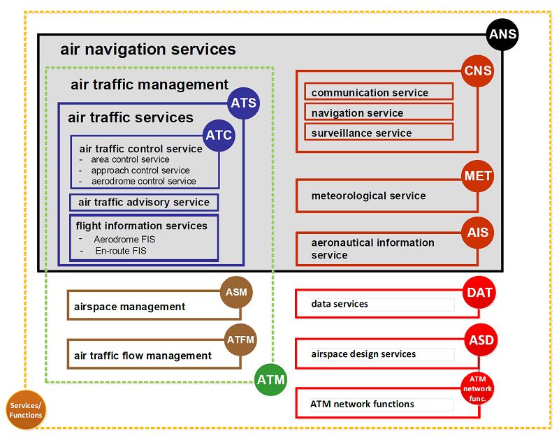
Figure 1. Air Navigation Services (EASA) ............................................................................................... 11
Figure 2. DAC Concept Axis ................................................................................................................... 15
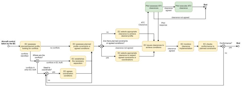
Figure 3. ATFCM Use Case Diagram ...................................................................................................... 25
Figure 4. CDR Use Case Diagram (Planning Separation) ....................................................................... 31
Figure 5. CDR Use Case Diagram (Tactical Separation) ......................................................................... 36
6D2.1 TAPAS USE CASES DESCRIPTION
1 Executive Summary
This document describes in detail the use cases to be developed under TAPAS project: (a) from the
operational point of view; and (b) from the technological perspective. It also contains the operational
context description in which TAPAS use cases are to be developed.
In particular, the following use cases are described:
• Conflict Detection and Resolution (CDR), during the tactical phase at the Executive Controller
Controller Working Position,
• Conflict Detection and Resolution (CDR), during the tactical phase at the Planner Controller
Controller Working Position, and
• Air Traffic Flow and Capacity Management (ATFCM), at pre-tactical phase.
With regards to the operational context, four main concepts have been identified to impact the
development of TAPAS Use Cases:
• Free-Route Operations;
• Trajectory Based Operations;
• Dynamic Airspace Configuration; and
• Flight Centric ATC.
7D2.1 TAPAS USE CASES DESCRIPTION
2 Introduction
2.1 Purpose of the document
The main objective of this document is to perform a state-of-the-art analysis in terms of operational
concept evolution and technology in order to develop and maintain a functional roadmap per each
one of the operational use cases addressed by TAPAS.
In particular, TAPAS will consider the following three operational cases:
• Conflict Detection and Resolution (CDR), during the tactical phase at the Executive Controller
Controller Working Position,
• Conflict Detection and Resolution (CDR), during the tactical phase at the Planner Controller
Controller Working Position, and
• Air Traffic Flow and Capacity Management (ATFCM), at pre-tactical phase.
This document will describe in detail these three operational use cases based on state-of-the-art
SESAR concept development and operational knowledge.
Complementary to the operational definition of the use cases, this document will collect and explore
the technological constraints and possibilities that need to be considered for a realistic overview of
the evolution possibilities. This technological view will be based on the industrial background of
TAPAS consortium, as well as the knowledge of operational Air Traffic Control (ATC) and Air Traffic
Management (ATM) tools and platforms, such as those intended to support the TAPAS cases studies,
including industrial approaches to automation in ATM (with and without AI/ML techniques).
This document will be used within the project as the operational basis to which the subsequent work
packages should refer to when deriving the AI transparency requirements and building the AI/ML
models.
2.2 Intended Readership
This document is intended to be used by:
• SJU programme manager;
• TAPAS project members;
• SESAR2020 and international research community addressing automation in Air Traffic
Management and Artificial Intelligence / Machine Learning.
2.3 Document Structure
This document is structured into the following sections:
8D2.1 TAPAS USE CASES DESCRIPTION
• Section 1 is the Executive Summary and provides an overview of the TAPAS operational use
cases.
• Section 2 is the Introduction that provides the purpose of the document, the intended
readership, the document structure and the terminology and acronyms used throughout the
document.
• Section 3 summarises the operational context of TAPAS under which the operational use
cases are developed.
• Section 4 describes the TAPAS operational use cases, from both operational and
technological point of view.
• Section 5 provides references used for the construction of the operational use cases.
2.4 Terminology and Acronyms
Term Definition
3D Three-Dimension
AI Artificial Intelligence
ADS-C Automatic Dependent Surveillance - Contract
ANSP Air Navigation Service Provider
AoI Area of Interest
AoR Area of Responsibility
ATC Air Traffic Control
ATCo Air Traffic Controller
ATFCM Air Traffic Flow and Capacity Management
ATM Air Traffic Management
ATS Air Traffic Services
CDR Conflict Detection and Resolution
CHMI Collaboration Human Machine Interface
CONOPS Concept of Operation
CS Configured Sector
CWP Controller Working Position
9D2.1 TAPAS USE CASES DESCRIPTION
DAC Dynamic Airspace Configuration
DCB Demand and Capacity Balancing
EAP Extended ATC Planner
EASA European Aviation Safety Agency
EC Executive Controller
EPP Extended Projected Profile
FAB Functional Airspace Blocks
FCA Flight Centric ATC
FDP Flight Data Processor
FMP Flow Management Position
FMS Flight Management System
HEC Hourly Entry Counts
ICAO International Civil Aviation Organisation
INAP Integrated Network ATC Planning
LTM Local Traffic Manager
ML Machine Learning
NM Network Manager
NOP Network Operations Plan
OCC Occupancy Counts
PC Planner Controller
RBT Reference Business Trajectory
RMT Reference Mission Trajectory
SESAR Single European Sky ATM Research
SWIM System Wide Information Management
TAPAS Towards an Automated and Explainable ATM System
TBO Trajectory Based Operations
10D2.1 TAPAS USE CASES DESCRIPTION
3 TAPAS Operational Context
This section provides context for the reader about the operational environment in which the TAPAS
use cases are included.
3.1 General Overview. Air Navigation Services
According to ICAO Doc. 4444 – Procedures for Air Navigation Services, Air Traffic Management is the
“dynamic, integrated management of air traffic and airspace including air traffic services, airspace
management and air traffic flow management — safely, economically and efficiently — through the
provision of facilities and seamless services in collaboration with all parties and involving airborne
and ground-based functions”.
Within the Air Navigation Services domain, the TAPAS project will focus specifically on Air Traffic Fow
and Capacity Management (ATFCM) and Air Traffic Control (ATC) Services. The first, is defined in
ICAO Annex 11 – Air Navigation Services as “a service established with the objective of contributing to
a safe, orderly and expeditious flow of air traffic by ensuring that ATC capacity is utilized to the
maximum extent possible and that the traffic volume is compatible with the capacities declared by
the appropriate ATS authority”; whilst the latter is defined as “a service provided for the purpose of:
a) preventing collisions: 1) between aircraft, and 2) on the maneuvering area between aircraft and
obstructions; and b) expediting and maintaining an orderly flow of air traffic”.
Figure 1. Air Navigation Services (EASA)
11D2.1 TAPAS USE CASES DESCRIPTION
3.2 Operational Environment
In this section, the descriptions of the operational concepts that support the TAPAS Use Cases are
presented. To this end, the vision of the SESAR programme has been considered.
3.2.1 Transversal Topics
3.2.1.1 Trajectory Based Operations
The concept of Trajectory Based Operations (TBO), which is one of the main pillars that supports the
SESAR target concept as stated in the ATM Master Plan, consists in allowing airspace users to fly their
preferred trajectories in order to deliver passengers and goods on time to their destination as cost-
efficiently as possible .
TBO relies on a full integration of flight information, enabling the ATM system to have a synchronised
view of the flight data by all the stakeholders involved. The sharing of a common reference trajectory
information via ground-ground and air-ground System Wide Information Management (SWIM)
throughout the Business / Mission Trajectory lifecycle will significantly improve ATM accuracy,
predictability and reliability.
According to the SESAR Concept Of Operations (CONOPS), high quality 4D trajectories data will be
made automatically available to all relevant stakeholders by means of cutting-edge ground-ground
trajectory exchange mechanisms. This will improve common situational awareness, automation and
global performance. It is also expected that TBO will enable increased collaboration and operational
predictability, by means of enhanced collaborative decision-making processes [1].
Finally, TBO will lead to efficiency gains, not only at the individual aircraft level, but for the network
as a whole. In this way, TBO will facilitate a fundamental shift away from flight management through
Air Traffic Control tactical interventions towards a more strategic focus on trajectory planning and
intervention by exception [5].
3.2.1.2 Free-Route Operations
Free Route Operations, that is, flights following as direct routes as possible between the origin and
destination, are enabled by the introduction of higher levels of automation in support of the
following processes [2]:
• Wide implementation of automated tools for conflict detection and resolution, flight
monitoring, and electronic coordination;
• Enhanced ATFCM with Integrated Network ATC Planning (INAP) offering a more optimised
granularity level for complexity management and Dynamic Airspace Configuration (DAC)
management;
• Advanced processes for airspace management, including Dynamic Airspace Configuration;
• Flight and flow centric operations.
The result is an airspace that is managed as a continuum, allowing a better use of airspace capacity,
and supporting an optimum demand-capacity balancing process by offering much more flexibility for
flight profiles optimisation based on user preferred trajectories.
12D2.1 TAPAS USE CASES DESCRIPTION
With free route airspace in high and very high complexity cross-border environments, the use of
Conflict Detection and Resolution support tools is considered mandatory to support the Planning and
Tactical Separation assurance.
3.2.2 Dynamic Airspace Configuration Concept
DAC is part of the SESAR 2020 Advanced Demand and Capacity Balancing concept, with enhanced
and fully integrated processes that ensures that all levels of the network are able to manage their
operations across all ATM phases to meet performance targets in a seamless and fully collaborative
basis [3].
In comparison with a sectorisation based on a fixed route network, with little flexibility to meet
demand requirements, the DAC concept introduces the idea of User Preferred Routes and new type
of flexible airspace reservations (Dynamic Mobile Areas - DMA). The objective is to develop airspace
designs and sector configuration schemes in order to optimise the use of the available capacity and
balance the Air Traffic Controller (ATCo) workload avoiding unnecessary intervention on the traffic
flows.
In the DAC environment, the number of controlled sectors and their shape can be adapted to the
current traffic situation at all ATM planning phases, from long term to execution. Thus, the DAC
process aims at identifying an optimised sector configuration based on the traffic demand and
predicted complexity, ATCos availability, and predefined performance targets.
The DAC concept comprises the following two main processes:
• Airspace design (in the long to medium term planning phases), supported by automated
tools for the definition of airspace structures and elementary sectors according to DAC
design principles.
• Sector Configuration Management (in the short term planning phase and during execution),
to help determine the optimum sector configuration that meets predicted demand for a
given period, considering multiple optimisation criteria and constraints (such as sector
overload, ATCo workload balancing, number of active sectors, available workforce etc.).
In order to achieve the DAC concept, a DAC toolbox is defined around three axes to support Air
Navigation Service Providers (ANSPs) in the management of airspace capacity and to facilitate Free
Routing Trajectories through varying degrees of sector dynamicity and automation:
• Design and Configuration Axis - introduces five different airspace design elements, which
can be configured into six different configurations, resulting in a Configured Sector (CS).
o Elementary Sector (ES), which is an ATC workable 3D airspace, that is, it can be
controlled by Air Traffic Controllers and they cannot be split further down into
controllable sectors.
o Airspace Blocks, which are primary volume of airspace that has to be configured to
build workable sectors.
o Shareable Airspace Block, which is a non-workable (that is, they cannot be controlled
by ATCOs) volume of airspace that can be dynamically configured in a pre-defined
13D2.1 TAPAS USE CASES DESCRIPTION
way to any adjacent Elementary Sector or Airspace Block to build a Configured
Sector.
o Flexible Boundaries, which are sector boundaries that can be modified or refined to
facilitate and optimise Free Routing Trajectories.
o Vertical Sharable Airspace Modules, which are non-workable volumes of airspace
vertically split in 1000 feet segments.
o Configured Sector, which is the result of the Sector Configuration process and in
which the ATCo is providing Air Traffic Services.
In addition, the following conceptual elements are defined:
o Dynamic Mobile Areas: these are an integral part of the Mission Trajectory described
by a 4D data set (geographical position x, y, z; time; velocity), where the velocity
parameter is equal to zero. Therefore, DMA constitutes a defined 3D volume of
airspace that satisfies specific requirements from different Airspace Users.
There are two types of DMAs that have been identified within SESAR Wave 1
concept:
▪ DMA Type 1 is a volume of airspace of defined dimensions as integral part of
Mission Trajectory at flexible geographical locations agreed upon a CDM
process, satisfying Airspace Users requirements in terms of a time and/or
distance constraint parameters from a reference point as specified by the AU
(e.g. Aerodrome of Departure).
▪ DMA Type 2 is a volume of airspace of defined dimensions described as
integral part of the Mission Trajectory and agreed upon a CDM process,
satisfying the Airspace Users requirements.
o Airspace Reservation (ARES Reservation): this allows users to create a specified
volume of airspace temporarily reserved for exclusive or specific use by categories of
users (e.g. military operations).
o ATC Volumes Reservation: this allows airspace managers to define volumes of civil
ATC airspace that are of high importance due to planned traffic load and/or
complexity and in which ARES operations should not be planned.
• Automation Axis - considered as essential to support the performance of the Dynamic
Airspace Configuration process. The automation will increase, amongst others, the range of
possibilities in organising and managing the airspace, the efficiency of solutions by using
optimisation algorithms, and the efficiency of the DAC decision-making process.
• Human and Training Axis - which conforms the last pillar of the DAC process and refers to
the interdependency of training requirements as dynamicity in the airspace configuration
increases; it also depends on the level of automation.
14D2.1 TAPAS USE CASES DESCRIPTION
Figure 2. DAC Concept Axis
3.2.3 Flight Centric ATC Concept
In the Flight Centric ATC concept, ATCos are no longer responsible for managing the entire traffic
within a given sector, but rather for managing a certain number of aircraft throughout their flight
segment within a larger airspace or along flows of traffic. This means that aircraft may be under the
responsibility of the same ATCo across two or more geographical sectors [7].
In terms of airspace, the FCA concept will dissolve the current sector boundaries for managing
separation provision across several sectors, in order to enable larger sectors to be used (e.g. the new
airspace distribution could be done at the level of Area Control Centres or Functional Airspace Blocks
(FAB)).
The change to a flight-centric structure, without reference to geographical sectors, will open up the
opportunity to better distribute the traffic and to avoid the loss of productivity in under-loaded
sectors. Other benefits are also expected, such as reduced fuel consumption and emissions,
enhanced predictability, improved operational and cost efficiency and maintained levels of safety.
In order to achieve the stated performance objectives, the introduction of a new role named
“allocator” is required, as well as changes in the responsibilities of the current Executive and
Planning Controllers.
• The allocator, supported by automated tools, is mainly responsible for the unequivocal
allocation of the incoming traffic depending on several static or dynamic allocation criteria
such as ATCo workload, complexity, flows, etc. The allocator is also responsible to allocate
the responsibility to solve a conflict to a particular Executive controller, if needed, and to
15D2.1 TAPAS USE CASES DESCRIPTION
balance, in coordination with the Flow Management actors, the demand and capacity in the
Flight Centric Area.
• The Executive Controller is responsible for:
o providing separation between controlled flights;
o providing separation through coordination;
o providing sequencing between controlled flights;
o identifying conflict risks between aircraft and solve the conflict;
o in case of conflict between aircraft under control of two different controllers
coordinating who shall solve the conflict;
o shared responsibility for conflict management;
o monitoring flights regarding adherence to flight plan/RBT/RMT;
o monitoring traffic not under control responsibility;
o monitoring weather conditions;
o may coordinate exit conditions directly;
o if necessary, transferring the flight to another Flight Centric Executive Controller (for
example for conflict resolution).
• The Planner Controller is responsible for:
o coordinating entry conditions;
o changing exit conditions on request by Flight Centric Executive Controller;
o providing early conflict detection and resolution (depending on the conflict detection
and resolution tools horizon, mainly supported by the Planner Controller Aid) for
conflicts before entering the Flight Centric Area;
o providing early conflict detection and resolution proposal to Executive Controllers for
conflicts inside the Flight Centric Area in a medium term horizon.
o input tactical trajectory changes into the Flight Data Processing System if requested
by a Flight Centric Executive Controller;
o assisting in Executive Controller tasks on request;
o re-assigning responsibility for specific aircraft from one Flight Centric Executive
Controller to another Flight Centric Executive Controller due to operational
procedures and/or on request;
o the Planner Controller could also apply level capping and rerouting of individual
flights internally in the Flight Centric Area to offload certain areas depending on the
time horizon and the DCB needs.
With regards to the three layers of Conflict Management, the FCA concept addresses all of them as
follows:
• Strategic Conflict Management: the nature of the concept allows a better integration of this
process through the distribution of conflicts by means of advanced allocation techniques and
use of predefined resolution strategies within the Flight Centric Area.
• Separation Provision: the Executive and Planner controllers are still responsible for
separation provision. Nevertheless, the Planner Controller is not only responsible for conflict
resolution before the flight enters the Flight Centric Area but also inside it, providing
16D2.1 TAPAS USE CASES DESCRIPTION
resolution proposals to the Executive Controller. In addition, the conflicting traffic may be
under the control of different Executive Controllers.
• Collision Avoidance: supported by the safety nets, the Executive Controller is responsible for
collision avoidance.
17D2.1 TAPAS USE CASES DESCRIPTION
4 TAPAS Operational Use Cases Description
In this section, the Operational Use Cases to be addressed by TAPAS are described both textually and
logically.
4.1 ATFCM Use Case
4.1.1 Definitions
In order to ease the reading of the ATFCM Use Case, a set of concepts and definitions are provided
below [12][13].
• Hourly Entry Counts (HEC): number of flights entering a Traffic Volume within a one-hour
time period.
• Occupancy Counts (OCC): number of flights that are inside a defined location at a precise
time and that correspond to the flights that are (or will be) worked by ATC at that time.
o Duration: Time Interval reference defined for a specific traffic volume. The interval is
used to evaluate and compare the load against the Occupancy Traffic Monitoring
Values (Peak and Sustained).
o Peak: Occupancy Traffic Monitoring Value defined for a specific duration interval. If
the load value in the traffic volume for the pre-defined duration exceeds the peak
value an alarm is triggered.
o Sustained: Occupancy Traffic Monitoring Value defined for a specific duration
interval. This value indicates the maximum sustained value manageable.
o Step: Time rolling interval for which a duration period is ‘moved’ to evaluate the
load.
o Elapse: Time interval that defines the ‘evaluating’ period of sustained value.
o Occurrence: Number of times that the load is above the sustained value defined.
• Hotspot: 4D volume (defined in time and space) representing a potential DCB, identified by
ANSP(s) and potentially the Network Manager.
• Optispot: 4D volume (defined in time and space) representing a traffic situation where
opportunity for optimisation has been identified by ANSP(s). An ATFCM situation yet to be
optimised represents a nominal, safe and planned event.
• Mandatory Cherry Picking regulation: DCB measure used to solve short peaks (e.g. 1h or 1h
30min) of limited number of flights in congested areas. It consists of selecting flights creating
complexity and applying ATFCM measures only to those flights.
18D2.1 TAPAS USE CASES DESCRIPTION
4.1.2 Scope
The scope of this use case is limited to the detection, declaration and resolution of imbalances during
the Pre-Tactical Phase, and particularly, focused on D-1 (day before operations). This includes not
only imbalances induced by existing differences between demand and capacity, but also induced by
the opportunity to improve performance levels.
4.1.3 Actors
4.1.3.1 Primary Actors
The primary actor is the Local Traffic Manager (LTM).
4.1.3.2 Supporting Actors
The supporting actors are the Air Traffic Service Unit Supervisor and the Network Manager.
4.1.4 Preconditions
Traffic demand from D-7 (seven days before operation) to D-1 (day before operations), that is Pre-
Tactical Phase, is available, allowing the Imbalance Monitoring and Prediction Service to calculate all
the imbalance methodologies outputs (mainly Hourly Entry Counts and Occupancy Counts).
Capacity figures, expressed for each possible configuration are also available, expressed in terms of
entry count capacities and Occupancy Traffic Monitoring Values (OTMV) counts, including both
maximum simultaneous occupancy and maximum sustained occupancy figures.
4.1.5 Post conditions
Once an imbalance is detected, the appropriate kind of spot is declared, and the required DCB
measures taken (both capacity and demand measures) at the Pre-Tactical Phase (up to D-1), the
Local Traffic Manager shall monitor the spot resolution status.
4.1.6 Success end state
The imbalance is detected, the appropriate spot is declared (hotspot or optispot, depending on the
nature of the imbalance), and the required DCB measures that solve the imbalance are taken.
4.1.7 Failure end state
The imbalance is not detected due to uncertain information, missing information or information
corrupted. Therefore, the spot is not declared nor solved, which can lead to an overload situation in
the Tactical Phase.
4.1.8 Trigger
The imbalance detection and resolution may be triggered by:
• an alert on the Traffic Volume capacity threshold violation;
19D2.1 TAPAS USE CASES DESCRIPTION
• an alert on the Occupancy Traffic Monitoring Values violation;
4.1.9 Use Case Flow
4.1.9.1 Main flow
• For each Traffic Volume under the Area of Responsibility of the LTM, the Traffic Counts
(Hourly Entry Counts, HEC and Occupancy Counts, OCC), are displayed to the LTM for their
continuous monitoring.
• For each Traffic Volume, the LTM analyses the information provided by the Imbalance
Prediction and Monitoring Service (i.e. HEC and OCC).
• If some of the local monitoring values established for a particular Traffic Volume are violated
(capacity, occupancy or performance), an alert is displayed to the LTM.
• The LTM analyses the alert issued by the system and decides, based on the nature of the
imbalance, the declaration of the appropriate spot.
o If the spot is safety-critical, the LTM declares a hotspot and publishes it into the
Network Operations Plan (NOP).
o If the spot is not safety-critical, that is, the spot is related to performance
optimisation, the LTM declares an optispot and publishes it into the NOP.
In general, and just as reference, the following predefined conditions might be applied to
distinguish between safety-critical and non safety-critical cases, based on Hourly Entry
Counts and Occupancy Counts criteria:
o Hourly Entry Counts: the situation is considered safety-critical if there is an
overload (HEC over 110% of capacity threshold) or there is more than one count
bar of HEC above the capacity threshold.
o Occupancy Counts: the situation is considered safety-critical if there is an
overload (Occupancy Peak threshold violated) or if the occupancy counts are
between the peak and sustained thresholds more than the occurrence
established for the elapse time defined.
• For the spot declared, the LTM analyses the nature and root causes of the spot complexity
based on the violation of the Traffic Counts (HEC, OCC) thresholds.
• Depending on the nature and severity of the spot, the LTM analyses if capacity measures are
appropriate for the spot resolution.
o The LTM evaluates the sectorisation plan and identifies if the change required to
solve the imbalance is a minor or major change:
▪ If the spot is to be resolved with a minor change, the LTM selects the
sectorisation, then selects an airspace element, remove the element from
the current sector and adds the appropriate element to an operational
sector. In addition, the DCB indicators are calculated and presented for the
proposed configuration.
20D2.1 TAPAS USE CASES DESCRIPTION
▪ If the spot is to be resolved by means of a major change, the LTM selects the
operational sector/area of interest, runs the sectorisation optimiser (system
that may be based on Artificial Intelligence algorithms or logical rules), and
assess the proposed configuration based on the DCB indicators calculated
and presented.
o Once the new sectorisation plan is decided, the LTM analyses its local DCB impact:
▪ If the local impact is positive, the LTM implements the new sector
configuration plan and publishes it into the NOP.
▪ If the local impact is negative, the LTM reassesses the sector configuration
plan and/or initiates the preparation of demand measures.
• If capacity measures are not adequate to resolve the spot, demand measures or a
combination of capacity and demand measures are to be evaluated.
o Elaboration of demand measures - ATFCM Scenarios
▪ Depending on the nature and severity of the hotspot declared, the LTM
selects the most appropriate type of ATFCM scenario (e.g. Level-Capping,
Horizontal Re-Routing). These are typically based on pre-defined ATFCM
scenarios provided by the Network Manager (NM), but customised solutions
may also be considered.
▪ The LTM, supported by the What-If tool, performs a local impact assessment
of the scenario selected and the candidate impacted flights in terms of a set
of indicators (e.g. HEC, OCC, Additional Distance or Time, Additional Fuel
Burnt, etc.)
▪ If the scenario causes impact outside the AoR of the LTM, then a Network
Impact Assessment will be requested and evaluated.
▪ If the local impact assessment and Network Impact Assessment (when
applicable) are both positive and the spot could be resolved with the
selected scenario, then the LTM implements the scenario and publish it into
the NOP. If not, other types of demand measures should be assessed via
What-If support.
o Elaboration of demand measures - Trajectory Measures
▪ Depending on the nature and severity the declared spot, the LTM selects the
most appropriate type of Trajectory Measure or combination of Trajectory
Measures to be applied (e.g. Level-Capping, Horizontal Re-Routing,
Mandatory Cherry Picking).
▪ The LTM selects the candidate flights or flows impacted by the trajectory
measure or combination of measures selected.
▪ The LTM, supported by the What-If tool, performs a local impact assessment
of the trajectory measure proposed and candidate flights selected in terms
21D2.1 TAPAS USE CASES DESCRIPTION
of the set of indicators. These indicators may vary depending on the type of
measure selected (e.g. HEC, OCC, Complexity, Delay, Additional Time,
Additional Distance, etc.). The assessment of the local impact includes the
assessment of the impact of the measure in adjacent sectors belonging to
the AoR of the LTM.
▪ If the measure or combination of measures selected has any kind of impact
outside the AoR of the LTM, then a Network Impact assessment will be
requested and evaluated.
▪ If the local impact assessment and Network Impact Assessment (when
applicable) are both positive and the spot could be resolved with the
selected measure or combination of demand measures, then the LTM
implements the measure and publish it into the NOP. If not, other the LTM
should launch the implementation of an ATFCM Regulation.
o Elaboration of demand measures – ATFCM Regulation
▪ The LTM, supported by the What-If tool, performs a local and network
impact assessment for the appropriate Regulation Period, Regulation Width
and Regulation Rate, and analyses the most appropriate parameters based
on indicators such OCC, HEC, total delay, average delay per flight, etc.
▪ The LTM request NM to implement the Regulation according to the What-If
results.
• Once the selected measures have been implemented, the LTM monitors the spot resolution
status, and if deviations are detected, the LTM assesses the need for corrective actions.
4.1.10 Failure flows
If the failure end state occurs, and there is a remaining imbalance that may lead to a safety issue,
then the spot shall be resolved by the LTM/EAP or Planner and Executive controller taking actions on
the impacted flights during the Tactical Phase.
4.1.11 Technological Context
Within European Airspace, the ATFCM activities have been performed by the LTM role using a
Collaboration Human Machine Interface (CHMI) provided by EUROCONTROL to have remote access
to the functionalities existing in the NM (Regional ATFCM system), constituting the FMP on the ATC
centre. This CHMI system interfaces the NM system through standardised B2B Web Services in order
to have access to the relevant NM functionalities.
Nevertheless, as part of SESAR programme activities (both during the original SESAR programme and
during the Wave 1 & 2), some further evolutions for the FMP have been considered, and different
industrial partners have started to develop new products with the aim of supporting Sub-Regional
and Local ATFCM activities, maintaining:
22D2.1 TAPAS USE CASES DESCRIPTION
• The B2B Web Services used by the CHMI, so the interface and interoperability with the
Regional ATFCM product is guaranteed (both to receive flight information, and to coordinate
the spots and the resolution measures)
• New interfaces with the local FDP systems, in order to improve the tactical phase
information of the planned flights.
Concerning the state-of-the-art functionalities for the detection of imbalances, those products are
designed to :
• Count the predicted HEC and OCC on configurable airspace volumes, and compare the
figures with the declared capacity for such airspace volumes (both the sustain capacity and
the peak capacity)
• Similarly, count also the expected traffic following a certain route or crossing a certain
fixpoint.
• Compute complexity figures, based on complex algorithms taking into account not only the
total number of flights, but also an assessment on how complex will be to manage each flight
taking into account flight-specific profile and other local characteristics.
• Compare those complexity figures with equivalent sustain and peak thresholds.
• Provide this information to the LTM through a user friendly interface, where the LTM can
have both a summary and a detailed view on all the imbalances detected, and where it can
declare OptiSpots or Hotspots.
On top of the functionalities to detect imbalances, current systems also include some functionality to
design and coordinate solutions to the declared spots. Those functionalities include:
• Supporting the LTM to perform those minimum adjustments on the sector boundaries and
shapes in order to solve an imbalance with the minimum impact to the sectorisation plan.
• The automatic identification of sectors configurations which would optimise the Demand and
Capacity Balance for a given number of available ATCOs, supporting DAC concept. The idea is
to propose a certain number of CSs that can be set in order to efficiently manage the existing
traffic load scenario, maintaining a balanced workload among the different ATCOs.
• The design of tentative measures in order to reduce the demand, including :
o Predefined measures. These are preconfigured measures for the most common
imbalances where certain known flows of traffic are involved, and for which a
standardised solution is defined (such as re-routing or level capping those flows).
o Ad-hoc trajectory measures, where the LTM can manually select (cherry-picking)
flights where certain trajectory measures are to be applied. These measures are used
for non-conventional imbalances, which are demanding some creative measures to
solve them.
o ATFCM regulations, constituting the strongest measure, where the LTM can select
those flights to be delayed/impacted.
23D2.1 TAPAS USE CASES DESCRIPTION
Concerning the demand measures, the current systems support the definition of what-if scenarios
where the impact of all the designed measures is displayed to the controller, in order to summarise:
• The foreseen resulting imbalances, if any, and
• The impact that each measure has on each flight, including the total delay and the predicted
extra fuel compared to the original scenario.
Once the LTM has designed a measure and has properly analysed its impact, the measure can be
coordinated with the NM and also internally (in case the measure solves any imbalance on the
tactical phase). The current industrial products support this coordination through the standardised
B2B Web Services.
It must be noted that the current automation level on those products is different if we compare the
capacity measures with the demand measures :
• Concerning the capacity measures, the existing products are already able to proactively
propose to the LTM the optimal sector plan taking into account some KPIs requested. This
way, the LTM only needs afterwards to agree and apply the proposed measure.
• Concerning the demand measures, no proactive solutions are proposed by the system. It just
enables the LTM to design the measure and evaluate its impact.
24D2.1 TAPAS USE CASES DESCRIPTION
Figure 3. ATFCM Use Case Diagram
25D2.1 TAPAS USE CASES DESCRIPTION
4.2 CDR Use Case (Planning Separation Assurance)
4.2.1 Scope
The scope of this use case concerns the conflict detection and resolution process in the planner
controller timeframe, as part of the planning separation assurance process.
4.2.2 Actors
4.2.2.1 Primary Actors
The primary actor is the Planner Controller.
4.2.2.2 Supporting Actors
The supporting actor is the Executive Controller.
4.2.3 Preconditions
Planning and Tactical separation standards for the Area of Interest are provided. These may be
dynamic according to the scenario being evaluated.
4.2.4 Post conditions
Once planning conflict detection and resolution is completed, tactical conflict detection and
resolution is applied.
4.2.5 Success end state
The planning conflict detection and resolution process identifies any potential conflict at the entry,
exit, and executive controller Area of Responsibility, agreeing on the flight entry and exit
coordination conditions.
4.2.6 Failure end state
The planning conflict detection and resolution process fails to identify the potential conflicts at the
entry, exit and executive controller Area of Responsibility; or the flight coordination conditions are
not agreed resulting in the flight being rejected.
4.2.7 Trigger
There is incoming traffic in the planning control Area of Interest.
4.2.8 Use Case Flow
4.2.8.1 Main flow
• For each one of the new incoming flights in the sector planning area of interest (AoI), the
planner controller (PC) assesses the offered entry coordination conditions of the upstream
26D2.1 TAPAS USE CASES DESCRIPTION
sector and flight desired profile in order to determine the existence of any planning problems
at the offered entry conditions.
• If conflicts are identified with the offered entry conditions, the PC will assess if the conflict
may be resolve by the executive controller (EC).
o If the resolution of the entry conflict by the EC is appropriate, then the PC will refer
to the EC, who will assess the conflict nature.
▪ If the entry conditions are accepted by the executive controller, then the PC
will agree the entry coordination conditions and determine safe potential
exit coordination conditions.
• The PC will assess the flight trajectory profile through the Area of
Responsibility (AoR) for executive controller suitability.
• If the sector profile and exit coordination conditions are suitable,
then the PC makes the coordination offer to the downstream sector.
o If the answer from the downstream sector planner controller
is positive with regards to the exit coordination conditions,
the flight is accepted.
o If the answer from the downstream sector planner controller
is negative, then the exit coordination conditions are due to
review by the PC to offer a counterproposal or the flight is
rejected as the last resort.
• If the sector profile or exit coordination conditions are not suitable,
then the PC will re-assess the flight plan trajectory to change the exit
coordination conditions or the flight path within the AoR.
▪ If the entry conditions are not accepted by the executive controller, then the
PC will revise the sector entry coordination conditions with the upstream
sector, making a counterproposal.
• If the revised entry coordination conditions are agreed, then the PC
will continue with the assessment of exit coordination conditions
and trajectory profile suitability through the AoR.
• If the revised entry coordination conditions are not agreed, then the
PC will reject the flight.
o If the resolution of the entry conflict by the EC is not appropriate, then the PC will
revise the sector entry coordination conditions with the upstream sector, making a
counterproposal.
▪ If the revised entry coordination conditions are agreed, then the PC will
continue with the assessment of exit coordination conditions and trajectory
profile suitability through the AoR.
27D2.1 TAPAS USE CASES DESCRIPTION
▪ If the revised entry coordination conditions are not agreed, then the PC will
reject the flight.
• If there are no conflicts identified with the offered entry conditions:
o The PC agrees the entry coordination conditions and determines safe potential exit
coordination conditions.
o The PC also assesses the flight trajectory profile through the Area of Responsibility
(AoR) for executive controller suitability.
▪ If the sector profile and exit coordination conditions are suitable, then the PC
makes the coordination offer to the downstream sector.
• If the answer from the downstream sector planner controller is
positive with regards to the exit coordination conditions, the flight is
accepted.
• If the answer from the downstream sector planner controller is
negative, then the exit coordination conditions are due to review by
the PC to offer a counterproposal or the flight is rejected as the last
resort.
▪ If the sector profile or exit coordination conditions are not suitable, then the
PC will re-assess the flight plan trajectory to change the exit coordination
conditions or the flight path within the AoR.
4.2.9 Failure flows
The failure end state occurs:
• If the entry coordination conditions are not agreed, then the flight shall be diverted to a
different sector.
• If the planning conflict detection and resolution process fails to identify conflicts at the entry
coordination conditions or throughout the executive controller AoR, then the executive
controller will be the one dealing with the all potential conflicts during the tactical conflict
detection and resolution phase.
4.2.10 Technological Context
The first CDR tools were initially designed in parallel to the first trajectory based ATC systems and
FDPs, assuming that the uncertainties around flight trajectory prediction would be low, and so the
predicted conflicts would be reliable.
Nevertheless, and following operational usage, it was concluded that the accuracy of ATC Planned
Trajectories is limited by the lack of information about airspace user’s preferences or meteorological
data. This limited accuracy implies an uncertainty on future aircraft position, which grows for longer
look-ahead horizons, and limits the confidence of the planner controller on the mid-term predicted
aircraft position. As the density/complexity of airspace increases, it was considered impossible to
28D2.1 TAPAS USE CASES DESCRIPTION
design, in a mid-term look-ahead horizon, a conflict free ground plan. Tactical intervention was then
needed to solve a significant number of conflicts, further contributing to the overall mid-term
uncertainty.
One of the key limitations of this trajectory prediction process is the limited quality of the
performance model of the aircraft, together with the lack of knowledge on FMS known vertical
restrictions and the crew-specific piloting preferences. All the previous combined results into a
significant uncertainty around the vertical speed that can/will be navigated.
In order to improve the CDR tools, two main approaches have been followed along the SESAR
programme.
4.2.10.1 First approach: to create CDR tools properly managing this uncertainty
During the original SESAR programme, some new tools were designed to manage existing uncertainty
around the predicted planned trajectory. This way, and aligned with the need to assess the entry
conditions, exit conditions and trajectory profile through the EC AoR, the following ideas were
validated:
• Firstly, entry risks are computed, where the most likely flight trajectories are evaluated in the
vicinity of the entry boundary, and around the predicted/coordinated entry level, in order to
detect other flights that could be in conflict with this entry one (either being other entry
flights, or exit flights).
• Similarly, to compute exit risks, where the most likely flight trajectories are evaluated in the
vicinity of the exit boundary, and around the predicted/coordinated exit level, in order to
detect other flights that could be in conflict with this entry one.
• Finally, to detect the risks along the sector AoR, considering the entry and exit levels
coordinated levels, and also other intermediate levels expected to be used along the sector
crossing (such as, potentially, the En-Route Cruise Level on that sector).
Due to the uncertainty of the trajectory prediction, the tools include big uncertainty margins around
any vertical manoeuvre expected to be executed within the concerned sector: both in terms of the
exact position where the manoeuvre will start, and also related with the vertical speed that is likely
to be navigated by the aircraft. As a result, in high-density and complexity airspaces, these tools
detect a significant amount of risks, where the objective for the planner is:
• To assess if the risks for the existing coordinated entry/exit levels, together with the planned
route are manageable by the EC;
• To analyse if any different entry or exit level, or any alternative routing within the sector AoR
would minimise the number of risks, in order to facilitate subsequent EC tasks.
Currently existing tools also allow to create what-if scenarios for modifications of both the entry/exit
levels as well as modifications of the route, in order to evaluate their associated risks.
Additionally, and during SESAR 2020, some new approaches to manage the uncertainty will be
explored. In particular, some partners will explore the possibility to use AI/ML in order to anticipate
the most likely aircraft trajectory across the AoR. This process will learn from flights history in order
to anticipate the trajectory in three dimensions:
29You can also read