DEMONSTRATION OF INTENSIVE SHELLFISH FARMING IN OPEN WATERS WITH RESILIENT AND AFFORDABLE MODULES - OPENMODE
←
→
Page content transcription
If your browser does not render page correctly, please read the page content below
Call: EMFF-BlueEconomy-2018. Type of Action: EMFF-AG

   Demonstration of intensive shellfish farming in OPEN
      waters with resilient and affordable MODulEs

                          Grant Agreement nº 863562
             Coordinator: Research & Development Concretes

       D5.1. – Maritime and operational safety guide

With the contribution of the European Maritime and Fisheries Fund of the European Union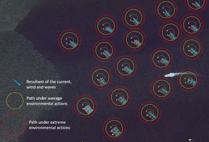
OpenMode-863562

 Deliverable Title                      Maritime and operational safety guide
 Deliverable No.                        5.1
 Related WP                             5. Design optimization
 Contractual date of Delivery           M9 (July 31st, 2020)
 Actual date of Delivery                M9 (July 31st, 2020)
 Deliverable Type                       R (Report)
 Dissemination level                    PUBLIC
 Lead beneficiary                       RDC
 Contributing participants              -
 Author(s)                              Cristina Maestre, Esteban Camacho
 Checked and approved by                Esteban Camacho
 Status                                 FINAL
 Description in the GA
                                        Guideline that describes the security measures for each step of the
                                        assembling, connections on open waters and operational activities.
                                        Measures to guarantee the maritime safety of in coastal and offshore
                                        waters. Updated in M15. Report, electronic format (PDF), approx. 90
                                        pages. Language: English and Spanish

Version History

 Version         Status       Date                           Contribution (Partner)             Summary of changes
 V0.1            Draft        24th, July 2020                Cristina Maestre (RDC), Draft Version
                                                             Esteban Camacho (RDC)
 V1.0            Final        31st, July 2020                Esteban Camacho (RDC)   Final Version

Disclaimer/ Acknowledgment

                  Copyright ©, all rights reserved. This document or any part thereof may not be made public or disclosed, copied or
                  otherwise reproduced or used in any form or by any means, without prior permission in writing from coordinator
of the OpenMode project. Neither the OpenMode Consortium nor any of its members, officer, employees or agents shall be liable or
responsible, in negligence or otherwise, for any loss, damage or expense whatever sustained by any person as a result of the use, in
any manner or form, of any knowledge, information or data contained in this document, or due to any inaccuracy, omission or error
therein contained.

All Intellectual Property Rights, know-how and information provided by and/or arising from this document, such as designs,
documentation, as well as preparatory material in that regard, is and shall remain the exclusive property of the OpenMode
Consortium and any of its members or its licensors. Nothing contained in this document shall give, or shall be construed as giving,
any right, title, ownership, interest, license or any other right in or to any IP, know-how and information.

This project is implemented with the contribution of the European Maritime and Fisheries Fund of the European Union, and has
received funding under grant agreement No 863562. The information and views set out in this publication does not necessarily reflect
the official opinion of the European Commission. Neither the European Union institutions and bodies nor any person acting on their
behalf, may be held responsible for the use which may be made of the information contained therein.

D5.1. Maritime and operational safety guide                                                                           2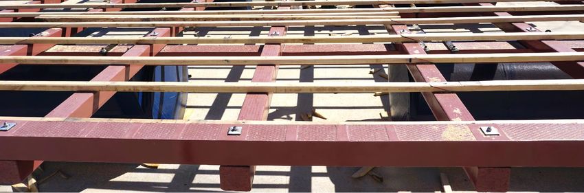
OpenMode-863562

                                 Executive summary

The Deliverable 5.1 is a public document that provides a global view of the different aspects that
affect to safety and health in the use of the Formex® modules proposed in the OpenMode project.
Aspects as maritime safety, occupational safety during the assembling and the farming, or the
innovative connection procedures are covered.

The steps where safety is relevant have been introduced in temporal order, starting from the
selection of a safe location for a floating module (climatological conditions and navigation are the
main factors to be considered), and ending with the operations on it. The risk of the assembling
procedures are detailed and quantified (from 0 to 3), describing after this what has to be considered
for a safe floating of the structure. For the case of the modules that can be connected, a safe
procedure and conditions to do this operation are described in section 5.

Section 6 describes the preventive and corrective safety measures to guarantee the maritime safety
of a floating module. The first include the procedures to beacon the element, the video camera for
control and the most common types of mooring systems. Among the corrective measures are the
GPS and the load-cell in the mooring, both systems proposed by RDC in this project as innovations
to report with an alert that a module is adrift.

Sections 7 (in English) and 8 (in Spanish) are a guide about the safety under service in the module.
It describes the Personal Protection Equipment that may be required working on it and the novelties
of the Formex® module compared with other marine aquaculture solutions. The risks working on
the module are quantified (0 to 3), indicating their causes and preventive measures. The section
includes the risks on the vessel as an element that may complement the work on a module. The
section finishes with a gender analysis of the safety using a module.

Finally, the Annex I provides a description of the production cycle of molluscs on a floating farm,
Annex II summarizes the legal procedures to propose the beaconing of a structure in Spain (where
there are already two mussel farming polygons beaconed) and Annex III provides a short guide of
knots to be used to reduce overexertion on the module.

D5.1. Maritime and operational safety guide                                                        3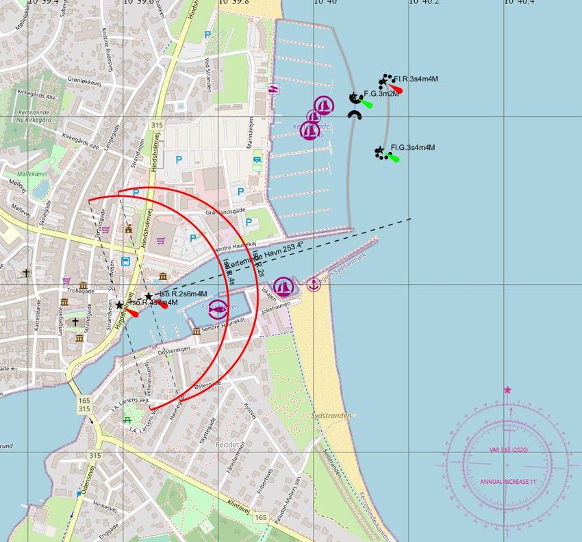
OpenMode-863562

Table of contents

1.     Introduction .............................................................................................................................. 12
     1.1.     Scope of this document..................................................................................................... 12

     1.2.     Audience............................................................................................................................ 12

     1.3.     Structure of the document................................................................................................ 13

     1.4.     Preliminary remarks and relevant concepts ..................................................................... 13

     1.5.     Legal frame ........................................................................................................................ 13

2.     Selection of a safe location for a module .................................................................................. 14
3.     Safety of the assembling procedures ........................................................................................ 16
4.     Safety of the floating procedures.............................................................................................. 21
5.     Safety of the on-water connection procedure.......................................................................... 25
6.     Maritime safety of the floating module .................................................................................... 28
     6.1.     Preventive ......................................................................................................................... 28

       6.1.1.        Beaconing .................................................................................................................. 28
       6.1.2.        Mooring system......................................................................................................... 31
       6.1.3.        Camera ...................................................................................................................... 32
     6.2.     Corrective .......................................................................................................................... 33

       6.2.1.        GPS ............................................................................................................................ 33
       6.2.2.        Load cell in the mooring ............................................................................................ 33
       6.2.3.        Camera ...................................................................................................................... 33
7.     Safety under service on the floating module (English) ............................................................. 33
     7.1.     Introduction ...................................................................................................................... 33

     7.2.     Personal Protection Equipment (PPE) to be used in a module ......................................... 34

     7.3.     Novelties of the Formex® module in terms of occupational safety .................................. 34

       7.3.1.        Structure.................................................................................................................... 35
       7.3.2.        Sensors ...................................................................................................................... 38
     7.4.     Risks of operations on the module ................................................................................... 38

     7.5.     Risks of operations on the vessel ...................................................................................... 42

     7.6.     Gender analysis of the use safe use of the modules......................................................... 44

D5.1. Maritime and operational safety guide                                                                                                          4
OpenMode-863562

8.     Seguridad en servicio sobre el modulo flotante (español) ....................................................... 45
     8.1.      Introducción ...................................................................................................................... 45

     8.2.      Equipos de Protección Individual (EPIs) que deben usarse en un módulo flotante ......... 46

     8.3.      Novedades de los módulos Formex® en términos de seguridad ocupacional ................. 46

       8.3.1.          Estructura .................................................................................................................. 47
       8.3.2.          Sensores .................................................................................................................... 50
     8.4.      Riesgos de operaciones en el módulo ............................................................................... 50

     8.5.      Riesgo de operaciones en el barco.................................................................................... 54

     8.6.      Análisis de género en la seguridad en el uso de los módulos ........................................... 56

9.     Food security (English) .............................................................................................................. 57
10.         Seguridad alimentaria (español) ........................................................................................... 58
11.         References ............................................................................................................................. 60
Annex I: Brief description of the production cycle of molluscs in an intensive floating farm .......... 62
Annex II: Summary of the legal procedures to propose a beaconing of an aquaculture installation in
Spain .................................................................................................................................................. 65
Annex III: Knots to reduce overexertion ........................................................................................... 69

D5.1. Maritime and operational safety guide                                                                                                             5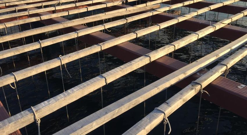
OpenMode-863562

List of figures

Figure 1. GANTT of the WP4 and WP5 of the project OpenMode..................................................... 12
Figure 2. Density of marine traffic in the North of Croatia (left) and in the coast of Montenegro (right).
The yellow spot indicates where the pilot module of this project will be located. Data obtained from
the website www.marinetraffic.com ................................................................................................ 15
Figure 3. Density of marine traffic in the Danish area of Kerteminde (left) and in the Danish area of
Nykøbing (right). The yellow spot indicates where the pilot module of this project will be located.
Data obtained from the website www.marinetraffic.com ................................................................ 15
Figure 4. Cruise ship entering in Valencia Port. The bow wave can be seen. It will arrive to the
Formex® farm after 2-3 minutes, creating a turbulence that favors the growth of the harvest ...... 16
Figure 5. Placing a floater of a Formex® raft (weight: 2.750 kg) ...................................................... 17
Figure 6. Left: Formex® frame adequately manipulated. The rigger uses a rope to guide the load and
the weight is equilibrated using the required slings. Right: Truck with load appropriately trimmed18
Figure 7. Formex® frame being lifted slowly to verify the equilibrium of the loads before staring the
process............................................................................................................................................... 18
Figure 8. Example of load chart of a 35-t mobile crane (Model: Liebherr LTM-1030-2.1). Source:
Liebherr ............................................................................................................................................. 19
Figure 9. Left: Scheme of a lifting platform; right: Recommendations for the use of stairs ............. 20
Figure 10. Tidal range global map. NASA/GSFC, Richard D. Ray ...................................................... 22
Figure 11. Sequence that shows the floating of a Formex® raft in Valencia port for the H2020 project
ReSHEALience-760824....................................................................................................................... 23
Figure 12. Positioning of the floaters and primary beams of a Formex® Plus raft in a ramp. Low tide.
........................................................................................................................................................... 23
Figure 13. Raft assembled one and a half day after starting the work. Tide is starting to rise ........ 24
Figure 14. Same raft as in figure XX, but two days later, with higher tide. The two mooring ropes to
avoid a possible drift of the module can be seen .............................................................................. 24
Figure 15. Formex® Mixta raft after assembling (favourable weather) and farmer towing the same
raft under adverse conditions (6 days later, with the arrival of the high tide) ................................. 24
Figure 16. Primary beams that should be used to start the on-water connection procedure .......... 26
Figure 17. Vessel towing a 540 m2 raft ............................................................................................. 27
Figure 18. Passing the ropes through the threaded plate of the first module .................................. 27
Figure 19. Passing the ropes through the threaded plate of the other module to connect both ..... 27
Figure 20. Pulling of the ropes to approach both structures and insert the bolts............................. 27
Figure 21. Lateral marks used in region A (Europe, África, and most of Asia) .................................. 28

D5.1. Maritime and operational safety guide                                                                                                                6
OpenMode-863562

Figure 22. Cardinal marks (left) and special marks (right) according to IALA-AISM ......................... 29
Figure 23. Example of Beaconing in Keterminde harbour, close to the location where one of the pilot
modules of the OpenMode project will be floated. Obtained from the portal
https://map.openseamap.org/ ......................................................................................................... 30
Figure 24. Area of drifting of floating farms in O Grove, Ria de Arousa. All the platforms are oriented
in a similar direction because each of them has only a single mooring ............................................ 31
Figure 25. Area of drifting of floating farms in Vigo Estuary. The platforms have the orientation
decided by their owner, which is different for each case. The area where the center of the raft can be
located is highted in bright yellow. ................................................................................................... 32
Figure 26. Beams of a Formex® module. The corners are smooth and the surface is homogeneous36
Figure 27. Detail of two different surface textures used in the Formex® modules ........................... 36
Figure 28. Secondary beams in continuous contact wiht the sea water. It can be observed a small
amount of green due to the continuous contact with the seawater. In Formex®, this can be removed
easily than in a wooden beam, which is an organic substrate.......................................................... 37
Figure 29. Scheme of the lifeline proposed for a Formex® module. Each side of the structure has a
length of 11.8 m ................................................................................................................................ 37
Figure 30. Left: Videocameras installed on the rafts of the project SELMUS-738777. Right: Second
generation of videocameras of RDC. Developed in the project OpenMode ...................................... 38
Figure 31. Adequate conection between the perimetral beam and the secondary beams. It can be
seen that the thread is at the top side .............................................................................................. 41
Figure 32. Safe values to reduce the risk of damage handling weights [16]..................................... 41
Figure 33. View of a Formex® raft from an inflatable boat. It can be noticed that the primary beam
is, aproximately, at the level of the head of the worker. .................................................................. 41
Figure 34. Mussel vessel. Source: Flickr............................................................................................. 42
Figura 35. Vigas de una batea Formex®. Nótese que los cantos están redondeados y la superficie es
homogénea ....................................................................................................................................... 48
Figura 36. Detalle de dos texturas diferentes en la superficie de una batea Formex® ..................... 48
Figura 37. Viga secundaria en contacto contínuo con el agua del mar. Se observa en la imagen una
pequeña cantidad de verdin en la superficie. Este se elimina con mayor facilidad que de la superficie
de la madera, que es un sustrato orgánico. ...................................................................................... 49
Figura 38. Esquema de las líneas de vida propuestas para un módulo Formex®. Cada uno de los lados
de la estructura tiene una longitud de 11.8 m .................................................................................. 49
Figure 39. Izquierda: Cámaras de video instaladas en las bateas del proyecto SELMUS-738777.
Derecha: Segunda generación de cámaras de video de RDC. Desarrollada en el proyecto OpenMode
........................................................................................................................................................... 50
Figure 40. Conexión entre látigo y vigas secundarias. Nótesé que la rosca está hacia arriba.......... 53

D5.1. Maritime and operational safety guide                                                                                                                7
OpenMode-863562

Figure 41. Valores de carga seguros estimados para reducir el riesgo de daño en la manipulación
manual [16] ....................................................................................................................................... 53
Figure 42. Vista de una batea Formex® desde una barca hinchable. Nótese que el operario está a la
altura de la viga primaria .................................................................................................................. 53
Figure 43. Barco mejillonero. Fuente: Flickr ...................................................................................... 54
Figure 44. State of the farming polygons in Galicia on February 12th, 2020 (blue: Open polygons (A
or B class). Red: Closed polygon for being in Class C). ...................................................................... 58
Figure 45. Estado de las zonas de cultivo en Galicia el 12 de febrero de 2020 (azul: Polígono abierto
(en clase A o B). Rojo: Polígono cerrado por alcanzar clase C). ........................................................ 59
Figure 46. Process of farming the mussel on floating farms and other systems (source: FAO) ........ 63
Figure 47. Type of beaconing installed in O Grove C, Galicia. In this case, it shows that the light
signalling is abandoned or destroyed. Obtained from the Spanish Ports network Portal AtoN. ...... 67
Figure 48. Type of beaconing installed in an experimental longline. All the beacons are under service.
Obtained from the Spanish Ports network Portal AtoN. ................................................................... 67
Figure 49. Incidences detected in a beacon and reported by a worker of Puertos del Estado.......... 68
Figure 50. Safe values........................................................................................................................ 69
Figure 51. Cuerdas de mejillón en batea Formex®. Polígono O Grove C2, Ría de Arousa, Galicia .... 69
Figure 52. Cuerdas de mejillón en batea Formex® (Puerto de Valencia) .......................................... 70
Figure 53. Bowline knot (“As de Guía” in Spanish) ............................................................................ 70

D5.1. Maritime and operational safety guide                                                                                                        8

OpenMode-863562

List of tables

Table 1. List of acronyms, abbreviations, and definitions ................................................................. 10
Table 2. Level of risks considered in the analysis .............................................................................. 17
Table 3. Risks identified for the assembling procedures ................................................................... 17
Table 4. Difference between the two main procedures to float the modules ................................... 21
Table 5. First numbers of Beaufort wind scale .................................................................................. 25
Table 6. List of PPEs that may be required for their use in a module ................................................ 34
Table 7. Level of risks considered in the analysis .............................................................................. 38
Table 8. Risks identified for the procedures working on a module ................................................... 39
Table 9. Occupation by gender in the different sub-sectors of the marine aquculture in Galicia.
Adapted from [24] ............................................................................................................................. 44
Table 10. Lista de los EPIs que se pueden requerir para acceder a un módulo ................................. 46
Tabla 11. Nivel de riesgo considerado en el análisis ......................................................................... 50
Tabla 12. Riesgos laborales asociados a los trabajos de engorde sobre el módulo o batea ............ 51
Tabla 13. Ocupación por géneros en las diferentes ramas de la acuicultura en Galicia. Adaptado de
[24] .................................................................................................................................................... 56

D5.1. Maritime and operational safety guide                                                                                                              9

OpenMode-863562

List of acronyms, abbreviations, and definitions
                       Table 1. List of acronyms, abbreviations, and definitions

 Abbreviations                                      Meaning
 ®               Registered
 AEMET           Agencia Española de Meteorología
 APROMAR         Employers' Association of Aquaculture Producers – Spain
 ASP             Amnesic shellfish poison
 AtoN            Ayudas a la Navegación marítima - Calidad
 BG              Blue Growth
 BV              Baseline Value
 CC.OO.          Workers Commissions (Spain)
 CIAIM           Commission of the Investigation of Maritime Accidents and Incidents
 COVID-19        Corona virus disease, year 2019
 DSP             Diarrhetic shellfish poison
 DXX             Deliverable number XX
 EASME           Executive Agency for SMEs
 EC              European Commission
 EMFF            European Maritime and Fishery Fund
 ES              Spain
 EU              European Union
 FRC             Fiber Reinforced Concrete
 H2020           Horizon 2020
 IALA            International Association of Marine Aids to Navigation and Lighthouse
                 Authorities
 IFC             International Finance Corporation
 IMCO            Maritime Consultive Organization
 In              Indicator
 IPR             Intellectual Property Rights
 ISO             International Organization for Standardization
 KPI             Key Performance Indicator
 MS              Milestone
 MXX             Month XX
 OC              Ordinary Concrete
 OHS             Occupational Health and Safety
 PPE             Personal Protective Equipment
 PREFFOR         Prefabricados Formex SL
 PSP             Paralytic shellfish poison
 R&D             Research and Development
 RDC             Research & Development Concretes SL
 SME             Small and Medium enterprise
 SO              Specific Objective

D5.1. Maritime and operational safety guide                                                     10
OpenMode-863562 SOLAS Safety of Life at Sea UHPC Ultra High-Performance Concrete UHPFRC Ultra High-Performance Fiber-Reinforced Concrete WP Work Package D5.1. Maritime and operational safety guide 11
OpenMode-863562

               1. Introduction
               1.1.           Scope of this document
        This public deliverable (D5.1) is the first of the WP5, which started in M4 and covers all the Operation
        and user experiences that support the penetration of the solution in the market. The file will be
        updated in the last month of the Task 5.1 (M15).

        The document identifies the risks and proposes safe procedures for all the steps of the module
        lifespan (assembling, floating, harvesting, connection on the sea…). Special attention is paid to the
        Occupational Health and Safety (OHS) working on the module and the beaconing of the structure,
        which differs from the long-line system typically used in most of the countries. The document
        quantifies the OHS risks of the different procedures and paying special attention to the navigation
        and beaconing.

        This text has obtained information from several guides for OHS in aquaculture, adapting it for the
        modules that have been designed in the WP2 of the OpenMode project. Finally, the deliverable
        provides a simple guide in English and in Spanish that may be used for the farmers to show them
        the most relevant facts to do a safe work on the platform.
                                                                                                Y1                                                      Y2
         Tasks. Milestones (red): X, Deliv erables (black,                Q1           Q2                Q3             Q4          Q5         Q6            Q7    Q8
                       updates in blue): X.X                      1       2    3   4   5    6        7   8    9     10 11 12 13 14 15 16 17 18 19 20 21 22 23 24
WP4 Manufacture and installation of the platforms
 4.1 Production of the precast elements                                                                       5               4.2
 4.2 Transport, assembling and floating to final location                                                           6   4.1

WP5 Operation and user ex periences
 5.1 Maritime and operational safety                                                                          5.1                        5.1
 5.2 E-LCA, Social-LCA and LCCA                                                                                                                                         5.2
 5.3 Analy sis of user ex periences and innov ation management                                                                                      5.3                 5.3
 5.4 Assembly of floating modules in different configurations                                                                                       7        5.4

 5.5 Optimization of operational activ ities through Big Data analy sis                                                                                                 5.5

                                               Figure 1. GANTT of the WP4 and WP5 of the project OpenMode

               1.2.           Audience
        The intended audience for this public Deliverable is:

        •      The farmers and amateurs that may potentially use the module during the project and in the
               future, both if they purchase it or if part of the farming area will be assigned to them for its
               temporary use.
        •      The potential investors and clients, as stakeholders interested in understanding the harvesting
               procedure before a possible purchase.
        •      The European Commission, as funding institution of this project.
        •      The employees of the companies RDC and PREFFOR that are participating in the OpenMode
               project.

        D5.1. Maritime and operational safety guide                                                                                                                12
OpenMode-863562
1.3. Structure of the document
The document is ordered treating in temporal order the safety of each step of the module lifespan:
Selection of a safe location, safe assembling, safe floating, safe connection, and safe use under
service conditions. The last is a brief guide for users and has been introduced first in English (section
7) and later in Spanish (section 8).
1.4. Preliminary remarks and relevant concepts
The company RDC and PREFFOR have cooperated for the development of this document. It is aligned
with the Environmental, Health and Safety General Guidelines of the International Finance
Corporation (IFC) of the World Bank Group [8].
In this text, the concept “open waters” implies the fact of being exposed to the waves with a
significant fetch. In all the cases, the concept of navigation used is Coastal Navigation according the
the IALA Navguide [11], which is limited to areas within 50 nautical miles (nm) from the shore or the
limit of the continental shelf (200 m in depth).
The documents included in the Annexes are not the core of the document but provide information
that has been considered interesting for a better understanding of certain aspects.
The information provided in this document is indicative, not contractual. The employees, owners,
assemblers and involved stakeholders are not exempt from conducting their own studies and
reviews regarding the occupational health and safety of their installations (module, vessel…).
Finally, the section Safety under service on the floating module is translated also to Spanish, as it is
considered a brief guide for the farmers that work on the module, and there are pilots of this project
which will be installed in Spain.
1.5. Legal frame
The installation of marine aquaculture elements is regulated in most of the countries of the world.
However, for mussel and oyster farming the most common element granted is the longline. The
authorization given by the Administration of the different countries is generally for the exploitation
of an area of water, where the farmer can use the system that he/she has described in the proposal.
It is not common to find limitations to the length or surface of the device used to harvest in the
authorized area, possibly because there are not yet floating structures in most of the countries in
the world. In the project OpenMode several pilot modules with an area of 140 m2 are going to be
floated in Denmark (2 elements), Croatia (1 element) and Montenegro (1 element), where there is
not experience with comparable structures for mollusc farming. The four authorizations requested
in these countries were approved before July 2020. From the point of view of occupational health
and safety, farming in this element is new in these locations, so there is no information in this field.
The most adequate is that a company expert in risk prevention visits the structure once it is installed
and indicates what measures and personal protection equipment are necessary.
The case of Spain is studied separately for having floating structures since the beginning of century
XX. In 1961 the harvest of mussel exploitations in marine waters (named as “maritime area”) was
D5.1. Maritime and operational safety guide 13OpenMode-863562
regulated. The largest farming region, Galicia, limited in 1986 the maximum area of a floating
structure to 540 m2 and the maximum length for the mussel ropes to 12 m. The objective of this
regulation was to reduce the pressure on the marine environment.
Regarding occupational health and safety, Spain approved in 2006 the Framework Collective
Agreement for the Marine Aquaculture, which embraced topics as the work organization, staff
classification, types of working sessions, working hours and resting periods and occupational health
and safety among other aspects. Since then, the labor relations in aquaculture have been regulated
with framework agreements between the business organizations and the union representations.
Currently in force, the V Collective Agreement for the marine national aquaculture was signed in
2019 by APROMAR (Employers' Association of Aquaculture Producers – Spain), the UGT (General
Workers' Confederation, Maritime and Port Sector), the State Federations of services to citizens of
the Workers Commissions (CC.OO.) representing the working community. This document excludes
the self-employed and all the employees from the mussel farming sector.
2. Selection of a safe location for a module
Five are the main factors that have influence in the selection of the location of a module, of which
two of them have a direct relation with safety. They are described as follows:
• Legal availability of the area to host mollusc farming installations. This factor depends on the
Aquaculture plan of the region or country.
• Biological suitability of the location to grow a good quality product.
• Depth: The depths lower than 8 m reduce the potential farming capacity of the module. Depths
higher than 35-40 m penalize the mooring costs and weights.
• Climatological conditions: This factor has an influence on safety. The farmers need to work on
the module and intense swell or wind may unbalance him significantly. Significant currents may
difficult the access from the vessel. In very cold waters (regions of Denmark, Norway…) the ice
can also involve risks: The wet surface of the module may slip during some winter days. In the
coldest regions, the ice of the water surface may damage the structure, so it needs to be
designed submersible.
• Risk for navigation: A factor that reduces the risks for navigation is to choose a location that has
a low density of marine traffic. This reduces the necessity to beacon the structure (which should
be decided by the corresponding authority) and avoids potential future accidents. There are
different online resources that indicate the density maps of marine traffic, as
www.marinetraffic.com. The figure below shows the traffic density of some of the pilot modules
that will be deployed in this project (yellow indicates medium density, red indicates high
density).
D5.1. Maritime and operational safety guide 14OpenMode-863562
Figure 2. Density of marine traffic in the North of Croatia (left) and in the coast of Montenegro (right). The
yellow spot indicates where the pilot module of this project will be located. Data obtained from the website
www.marinetraffic.com
Figure 3. Density of marine traffic in the Danish area of Kerteminde (left) and in the Danish area of Nykøbing
(right). The yellow spot indicates where the pilot module of this project will be located. Data obtained from
the website www.marinetraffic.com
It should be mentioned that, despite the potential risk of having mollusc farming installations close
to high density of marine traffic, this fact generates a recurrent swell (bow wave) that can boost the
entrance of nutrients, which increases the growing rates and improves the productiveness (see
figure 4).
D5.1. Maritime and operational safety guide 15OpenMode-863562
Figure 4. Cruise ship entering in Valencia Port. The bow wave can be seen. It will arrive to the Formex® farm
after 2-3 minutes, creating a turbulence that favours the growth of the harvest
3. Safety of the assembling procedures
The assembling procedure is the process to connect the precast elements to create a floating
module. Generally, and depending on the region where the module is going to be installed, it
requires an approved Project that includes a Safety and Health Study that covers the assembling
steps.
The heaviest single elements are the floaters, with a weight of approx. 2 ton. The most significant
factors that affect to the safety in the assembling procedure are:
• Assembling location: It can be in a flat flooring (port, deck…) or in the natural land of the
coastline. The last may be only used if the floating procedure will be done using the tides.
• Working height: The sum of the diameter of the floaters and the depth of the beams will
provide the maximum working height, which depending on the type of module may vary
between 1,80 m and 3 m. Generally, a work is considered “at a height” when the distance
from the feet of the worker to the flat surface exceeds the 2 meters.
The assembling can be carried out by any assembling team that is able to follow the assembling
instructions provided by PREFFOR, including the safety procedures. Generally, an assembling team
counts with 3 or 4 coordinated members. When the team is experienced in the field, they can
assemble a 140 m2 module in (6 to 8 hours, three employees), and a 540 m2 Formex® raft in 2 days
(16 hours, four employees). The works generally also require a crane driver and a rigger to support
its works.
The following table shows the most frequent and significant risks that can be suffered in the
assembling of a module.
D5.1. Maritime and operational safety guide 16OpenMode-863562
Minimum surface to assemble the module: 24 x 24 m, completely clear to avoid tripping or falling
and to facilitate the maneuver with the trucks, forklifts, and cranes.
The operators need to use the working clothes, helmet, leather gloves, security boots, rain clothes
(if necessary), type C safety harness (if necessary), protection glasses and reflective vest.
The left column is in different color depending on its risk. The risk is considered the severity of the
damage multiplied per the probability of occurrence. The risk can be identified in the colors
indicated below:
Table 2. Level of risks considered in the analysis
0 1 2 3
Not required to improve Take actions to reduce Work should not start
Action not required
the preventive action the risk until reducing the risk
Table 3. Risks identified for the assembling procedures
Risks of assembling the module
Significant risks
Causes Preventive measures
during assembling
Cranes, trucks, forklifts, lifting platform
Follow the regulations regarding the use of the crane and the
Inadequate
forklift. Use of slings and cranes according to the loads manipulated
handling with the
Falling of elements (they should have a plate that indicates the maximum load) and
slings and/or
lifted with the crane always using the safety lock. Inspection of the slings and hooks.
incorrect
or forklift Manipulation of the load without abruptness. Avoid the pass of
movements with
personal under the load manipulated. If any anomaly in the crane is
the machines
identified during the works, they should be stopped.
Figure 5. Placing a floater of a Formex® raft (weight: 2.750 kg)
D5.1. Maritime and operational safety guide 17OpenMode-863562
Propper and accurate planning of the handling of the elements,
considering all the construction steps. The crane driver should have
an adequate visibility of the load lifted, and, if not possible, it should
count with auxiliary support. The crane driver should position its
Knocks and blows of
Improper cable vertical over the center of the load to be charted to avoid
the load
placement of the movements with the lifting. The equilibrium should be verified with
manipulated
crane or elements a minimum lifting in its location. The driver will only lift and
against other
lifted manipulate the load under the orders of the rigger (always with the
objects
required expertise). Avoid dragging the loads. Avoid working with
wind speed higher than 50 km/h. Finally, the load of the truck must
be adequately trimmed to avoid movements caused by an
accidental knock.
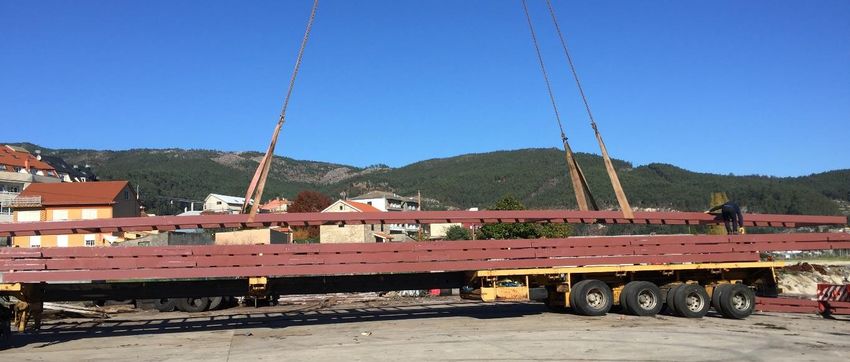
Figure 6. Left: Formex® frame adequately manipulated. The rigger uses a rope to guide the load and the weight
is equilibrated using the required slings. Right: Truck with load appropriately trimmed
Figure 7. Formex® frame being lifted slowly to verify the equilibrium of the loads before staring the process
D5.1. Maritime and operational safety guide 18OpenMode-863562
Adequate planning of the loads and distances that will be
manipulated with the crane. The driver must know the approximate
weight that the crane is carrying. This work should be done together
Excess of load
with the company that rents the cranes, which has the required
Rollover of the related to the
expertise interpreting the load chart. Besides, the floor should be
crane position of the
flat and have the adequate loading capacity (otherwise, the load
telescopic arm
chart of the crane does not apply). Avoid the sudden stop of the
loads that descend rapidly. The works should not start or should
stop with winds speeds over 50 km/h.
Figure 8. Example of load chart of a 35-t mobile crane (Model: Liebherr LTM-1030-2.1). Source: Liebherr
Inadequate
delimitation and The rigger should support the maneuvers of access of the large
Runover of people supervision of the trucks and cranes. The crane driver must, before starting the path,
around the crane or area of works, to inspect the itinerary. The signaling and lighting of the works
the trucks combined with a should be done by the client and according to the Safety and Health
distraction of the Study.
driver
Rollover due to an
instability of the It is forbidden the use of the platform without the required specific
Rollover of the ground, an excess training. Besides, it will be used according to the manufacturer's
lifting platform of load or the instructions. All the movements must be started slow to avoid
influence of a rollovers caused by a confusion.
wind gust
D5.1. Maritime and operational safety guide 19OpenMode-863562
Falling of the workers
Imbalance, wind Follow the Non-binding guide to good practice concerning the
Falling from module
gust, slippery minimum safety and health requirements for the use of work
surface to the floor
surface… equipment by workers at work (work at height) [22]
The stairs should be used for a maximum height of 5 m, and never
Slipping of the to carry loads over 20 kg. The stair should exceed in high at least 1
Falling from the
stairs, break, or meter the location to access. When supported in a vertical wall, it
stairs
imbalance should form an angle of approx. 15 degrees with it (figure 9). The
use of the proper footwear is mandatory.
Figure 9. Left: Scheme of a lifting platform; right: Recommendations for the use of stairs
Use of the tools
Use the available accessories that are in the crane or truck to get
Falling from the Imbalance, wind into and get out from the crane, and only when the machine is
height of the crane gust, slippery stopped. Verify from the cabin the floor before starting to get out.
or trucks surface… During the night, light the area of the floor to get out. Avoid using
the hook of the crane to access the crane.
Fall from the
Do not leave the tools in small locations (beams, balconies, stairs…),
module or fall
storing them always on their final position. Use of special belts to
Fall of the tools when a worker
store them for the tools used more frequently. Do not throw tools
throws it to
to other workmates.
another worker
Use of the required personal protection equipment. Use only of
approved and reviewed tool, and only by personnel that has been
trained for their use. The tools should be unplugged even for short
Inadequate use of stops. The cut-off disks and drill bits should be the adequate for
Injuries or knocks
the tools or use of each material, and they must be replaced only with the machine
with the tools
tools in bad shape unplugged. The machines cannot be used with rain or in humid
environment, unless otherwise stated. Never use for a work tools
that were designed to do other works, as it may harm the user
and/or break the tool.
Use the auxiliary tools designed for each specific case: forklifts,
Repetitive loading
Overexertion spikes… etc. Follow the recommendations of how to carry weights
of heavy loads, or
(see references [16] and [17]). Never turn the trunk loading weight.
D5.1. Maritime and operational safety guide 20OpenMode-863562
abrupt loading of
very heavy load
it is mandatory the use of the mask during the works where the
employee can be physically close to other workers. The mask is
Works carried out
recommended even when it is possible to keep the safe distance.
without mask
The use of hydroalcoholic gel is mandatory before and after using
Risk of transmission and/or not
common tools. it is recommended to follow an updated Guidance
of COVID-19 or keeping the
for a safe working environment under COVID-19 situation, as [23],
others required safe
which provides links to the recommendations for different sectors
distance (1.5 m in
in different countries (considering the high level of research
Spain)
ongoing for a better understanding of the COVID-19, it is
recommended to the reader to search an updated guidance)
4. Safety of the floating procedures
There are mainly two different procedures to float a module. The first is using a crane, and it is
chosen if the module was assembled in a port or flat area. The second is using the tides and a ramp
with access to the water, so it can be used only in regions with a tide higher than 2 m. The constrains
of each system are summarized in the table:
Table 4. Difference between the two main procedures to float the modules
Using crane Using tidal range
Higher costs (cranes between 100 and Lower costs, mainly the vessel used to tow
Costs
500 ton) the module
Despite that the module occupies the area
Timing of the
Between 2 and 6 hours during some days, the floating and towing
procedure
requires workers during only half a day
Timing Constrained to the permits provided by Constrained to the period between the high
constrains the owner of the area and the low tides
Geographic Possible in any region where a large Possible only in locations with tidal range
location mobile crane is available and has access higher than 2 m (see figure 10)
Requires a flat pavement with sufficient Requires a ramp or relatively stable area
Area
loading capacity next to the water
Requires a high expertise in understanding
Mainly, understanding the behavior and the tide tables and to handle floating
Expertise
load chart of heavy mobile cranes and structures, because the increase of the tide
required
the bearing capacity of a pavement will make that the module pass suddenly
from static to floating conditions
If the operation does not affect to natural
Administrative Obtaining a license to do the operations
protected area, obtain the license to do the
constrains may be moderately complex
works may be relatively easy.
D5.1. Maritime and operational safety guide 21OpenMode-863562
Figure 10. Tidal range global map. NASA/GSFC, Richard D. Ray
Each of the procedures are shown in the figures 11 to 15. Floating the structure with the crane has
some of the risks mentioned in the previous chapter (rollover of the crane, failing of the structure,
knocks…), but this work is one of the main steps of the installation of a module and it is generally
studied in detail, involving the producer of the structure (PREFFOR), the client (which will tow the
structure once it is floating), the owner of the area (which has data of accesses and the pavement
bearing capacity) and the crane rental company, which has high expertise of the capacity and
performance of its machines. Thus, the risks of the operation are low (probability of occurrence)
because the severity of an accident would be very high.
D5.1. Maritime and operational safety guide 22OpenMode-863562
Figure 11. Sequence that shows the floating of a Formex® raft in Valencia port for the H2020 project
ReSHEALience-760824
In the case of floating using the tidal range, the high tide can coincide with different meteorological
conditions (wind, storm, waves). This implies that it is a less controlled process than floating with a
crane, which is only used under favorable conditions. Thus, when using the tide, the module must
be adequately anchored to be sure that, if the floating and towing operation is not possible, the
module does not drift with the higher water level. Besides, the operators should also access the
platform to tie the ropes with enough time to assure that the module will not float. Otherwise, they
may be crushed or beaten by a sudden movement of the module.
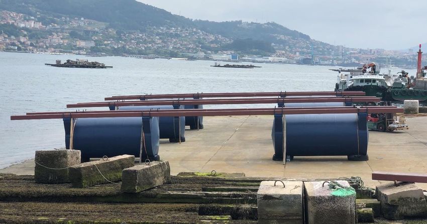
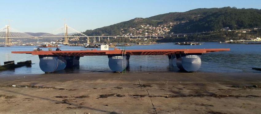
Figure 12. Positioning of the floaters and primary beams of a Formex® Plus raft in a ramp. Low tide.
D5.1. Maritime and operational safety guide 23OpenMode-863562
Figure 13. Raft assembled one and a half day after starting the work. Tide is starting to rise
Figure 14. Same raft as in figure 13, but two days later, with higher tide. The two mooring ropes to avoid a
possible drift of the module can be seen
Figure 15. Formex® Mixta raft after assembling (favourable weather) and farmer towing the same raft under
adverse conditions (6 days later, with the arrival of the high tide)
D5.1. Maritime and operational safety guide 24OpenMode-863562
5. Safety of the on-water connection procedure
The design of the connection system between modules was made to facilitate as maximum as
possible the procedure of assembling. For this reason, among others, pin connections were avoided.
The assembling procedure is recommended with the structures floating on the water, eliminating
then the costs of floating a larger structure, which is created on the water. The tools required to do
a safe and efficient connections are:
• At least three operators, two over module 1 (moored) and one another over module 2.
• A vessel or boat with capacity to tow one of the modules.
• Four ropes with a minimum length of 25 m and 12 to 20 mm of diameter.
The conditions that are recommended for the operation of connection are:
• Waves: Calmed (glassy or rippled) sea, with a maximum wave height of 10 cm. This implies
a degree under the Doublas Sea scale of 0 or 1.
• Current: the water current in the area should be reduced, with a maximum of 0.2 m/s.
• Wind: The wind conditions should be between 0 and 2 in Beaufort Scale
• The modules should be in similar loading conditions to have the primary beams at a similar
distance from the water surface. The most adequate is to do the procedure with both
structures without harvest (lightship weight).
Table 5. First numbers of Beaufort wind scale
Beaufort Wind speed Wind speed Wind speed
Description Wind effects on land
number (miles/hour) (km/hour) (knots)
0OpenMode-863562
3. The operator will use the ropes in the external primary beam of each of the two lines of floaters
(marked in red in figure 16). It will pass one rope through one of the diagonal threaded holes of
the steel plate. The knot in the extreme will allow to pull the module using the other extreme
of the rope. The same procedure will be done with the second rope in the opposite hole of the
same plate (figure 18). The same will be done for the plate of the other extreme primary beam.
4. The worker will roll the ropes, preparing them to be launched to the workers that are on module
2. Meanwhile, a vessel should tow the module 2 to approach it to module 1.
5. Once they are close (a distance lower than 10 m), the worker on module 2 will launch the roll of
ropes of each primary beam to each of the operators on module 1, which is moored. They will
pass the rope through the equivalent threaded holes of the module 1 (figure 19), and they will
start to pull progressively and in a coordinated way. The environmental conditions will allow the
module 2 to come closer to the 1.
6. Once the plates are confronted and placed in the proper relative position, the worker should
keep the rope pulled and insert the first bolt with a nut, screwing without tightening it (figure
20). Later, the next bolt should be placed in the opposite hole of the steel plate. After it, the
ropes can be released to insert all the threaded elements of the plates.
7. It is convenient to insert all the bolts of the four connections before tightening them to facilitate
a better alignment. After tightening them, the connection procedure will be finished.
Figure 16. Primary beams that should be used to start the on-water connection procedure
D5.1. Maritime and operational safety guide 26OpenMode-863562
Figure 17. Vessel towing a 540 m2 raft
Figure 18. Passing the ropes through the threaded plate of the first module
Figure 19. Passing the ropes through the threaded plate of the other module to connect both
Figure 20. Pulling of the ropes to approach both structures and insert the bolts
D5.1. Maritime and operational safety guide 27OpenMode-863562
6. Maritime safety of the floating module
6.1. Preventive
6.1.1. Beaconing
Legal frame
Aquaculture installations, including shellfish farms, are generally located in two different geographic
areas: The first are marshes and estuaries, and the second is the coastal area in the maritime-
terrestrial public domain, which covers from the coastal line to the 50-60 m in depth [7]. Generally,
the installations are moored in locations with a depth from 15 to 50 m, and in a distance to the
coastline that does not exceed the 2-3 miles perpendicularly to the coast. These locations are
required to make the farming accessible and economically viable for the farmers, but they also may
imply a potential risk for the navigation and coastal shipping. To minimize these conflicts to
navigation, the non-profit association AISM-IALA was created in 1957. Its purpose is harmonizing
aids to navigation. This association elaborates a document that is periodically updated.
Procedure
The beaconing of any aquaculture marine installation, including the modules for mollusc farming,
will depend on the established by the competent authority on each country (Puertos del Estado in
the case of Spain), which has the competence to accept the type of signals proposed in the
beaconing project. There are different scenarios for the beaconing of aquaculture installations
depending on what is established by the Lighthouses Commission (adapted from [15]):
1) When the marine aquaculture installation may imply a risk for the maritime navigation, it must
be beaconed according to the rules of the International Association of Marine Aids to Navigation
and Lighthouse Authorities (IALA AISM, www.iala-asim.org), using for this the following visual aids
to navigation: Special marks, lateral marks, cardinal marks, or a combination of them.
Figure 21. Lateral marks used in region A (Europe, África, and most of Asia)
D5.1. Maritime and operational safety guide 28OpenMode-863562
Figure 22. Cardinal marks (left) and special marks (right) according to IALA-AISM
2) If the special marks are used, the floating installation should be beaconed using the marks in the
apexes of an area that embraces not only the floating element, but also all its mooring system.
However, depending on the size of the element it may be enough to beacon only the perimeter of
the area covered by the floating element, or simply its centre.
3) For isolated facilities with shape of elongated rectangle, it may be convenient to beacon the two
longest sides with special marks with different rhythms.
4) If there are several marine installations nearby, it is convenient to beacon each of them using
different rhythms for the adjacent and following the rhythm of progression indicated by AISM/IALA.
5) If there is vessel traffic across an installation or between close installations, the channels that will
be created for the navigation should be beaconed with lateral marks.
6) If the circumstances were to make it advisable, the beaconing may consist only of cardinal marks
to maintain the marine traffic far from the floating installation.
7) To improve the perception of the beaconing in a marine installation, it must be considered the
synchronization of the rhythm of its lights.
8) To support the previously mentioned aids, radar reflectors and radio-electric aids, as racons and
intensifiers of radar target tracking may be used.
D5.1. Maritime and operational safety guide 29OpenMode-863562
Figure 23. Example of Beaconing in Keterminde harbour, close to the location where one of the pilot modules
of the OpenMode project will be floated. Obtained from the portal https://map.openseamap.org/
Example of beaconing of floating farms in Spain
In 1985, Spain decided to adopt for the Spanish waters the beaconing system proposed by the AISM-
IALA to avoid any difference between the system in the country and the system used by most of the
other coastal countries. This was approved by of the Maritime Safety Committee of the Maritime
Consultive Organization (IMCO).
As an example, the case of Galicia (the largest world area with floating farms for mussel farming) is
studied here. The mollusc farming areas located in the estuaries in Galicia are not yet completely
beaconed. The floating structures are 3.386 divided in 6 estuaries and 44 polygons. Only two
estuaries (Baiona, with one polygon [10]; and Muros-Noia, with four polygons [9]) were beaconed
in 2015 and 2019 respectively. Their floating structures represent only 4% of all the structures in
Galicia. The beaconing installed consists of lighting the four vertex of the polygon and all the
locations that are considered risky for the navigation. The light signals used are moored with a
concrete block.
The most significant barriers that have prevented the beaconing of the elements are:
• It needs to coordinate several stakeholders, as the Port Authority, Portos de Galicia, General
Secretary of the Coast and the Sea, Xunta de Galicia, etc. Annex II includes a description of
the legal procedures to do a beaconing project in Spain.
D5.1. Maritime and operational safety guide 30You can also read