Aeronautical Engineering - Master Thesis - idUS
←
→
Page content transcription
If your browser does not render page correctly, please read the page content below
Master Thesis
Aeronautical Engineering

A preliminary study of Models for Manufacturing to
define aeronautical assembly lines in 3DExperience

Author: Guillermo Álvarez Murcia
Tutor: Domingo Morales Palma

                                          Equation Chapter 1 Section 1

          Dpto. Ingeniería Mecánica y Fabricación
          Escuela Técnica Superior de Ingeniería
                   Universidad de Sevilla
                       Sevilla, 2021
Master Thesis
                 Aeronautical Engineering

A preliminary study of Models for Manufacturing
     to define aeronautical assembly lines in
                  3DExperience

                            Author:
                   Guillermo Álvarez Murcia

                             Tutor:
                    Domingo Morales Palma
                   Profesor Contratado Doctor

           Dpto. Ingeniería Mecánica y Fabricación
            Escuela Técnica Superior de Ingeniería
                   Universidad de Sevilla
                          Sevilla, 2021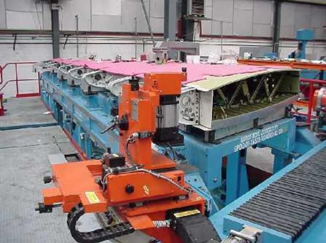
Master Thesis: A preliminary study of Models for Manufacturing to define aeronautical assembly lines in
                                             3DExperience

       Autor:   Guillermo Álvarez Murcia

       Tutor:   Domingo Morales Palma

El tribunal nombrado para juzgar el Proyecto arriba indicado, compuesto por los siguientes miembros:

Presidente:

Vocales:

Secretario:

  Acuerdan otorgarle la calificación de:

                                                       Sevilla, 2021

                                                                   El Secretario del Tribunal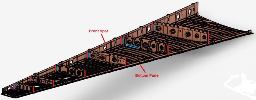
For my friends and family,
Acknowledgements

I want to thank to everyone who have made this project possible, directly or not.
First, I would like to thank Domingo Morales Palma, for its mentoring, supervision, patience, and knowledge,
for trusting me and giving me the chance of doing this, and his big help even in these extraordinary and
difficult circumstances.
I want to thank my family too, my parents and sister, for cheering me up during the whole project
development, encourage me so as to never give up, and hugely contribute to being myself nowadays.
Finally, I want to sincerely thank my friends, for their company and support whenever was needed, even
during difficult times.

Thanks to all.
                                                                                    Guillermo Álvarez Murcia
                                                                                                Sevilla, 2021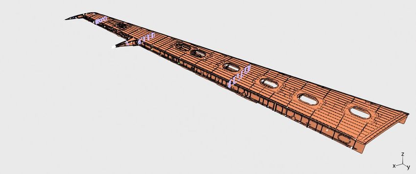
Abstract

Models for Manufacturing (MfM) is a preliminary approach to a methodology that aims to provide a set of
processes, methods and associated tools to help the engineers to support the discipline of manufacturing in a
model-based context. It is a proposal from a multidisciplinary team from the University of Seville in
collaboration with professionals from the aeronautical sector. MfM is currently in its early stages of
development.
The MfM methodology relays on the development of a reference framework, the 3LM (3-Layers Model: Data,
Ontology and Service layers), based on the definition of a manufacturing ontology and enabling simulation,
behaviors and analytical capabilities, capitalizing the company knowledge. The Ontology layer is the core of
the model. It holds all the company processes and scope, data and semantic models, and the associated
simulation or behavior requirements. At the beginning of this work there were proposals for the Scope and
Data models but not for the Behavior and Semantic models.
This project aims to collaborate in the development of the MfM methodology. The main contributions of this
work are: (1) a knowledge representation scheme is proposed to model the behaviour of the system under
study; (2) the application of the methodology to the aeronautical assembly line design process is analysed; and
(3) a model of the assembly process of an aircraft wing box is built in 3DExperience, in order to be used in
future performance tests of the MfM methodology.
Resumen

Models for Manufacturing (MfM) es una aproximación preliminar hacia una metodología que pretende
suministrar una serie de procesos, métodos y herramientas asociadas para ayudar a los ingenieros a cimentar la
disciplina de la fabricación en un contexto basado en modelos. Es una propuesta de un equipo multidisciplinar
de la Universidad de Sevila, en colaboración con profesionales del sector aeronáutico. El MfM está
actualmente en fases tempranas de desarrollo.
La metodología MfM recae en el desarrollo de un marco de referencia, el 3LM (3-Layers Model: capas Data,
Ontology y Service), basado en la definición de una ontología de fabricación y habilitando las capacidades de
simulación, comportamiento y análisis, priorizando el conocimiento de la empresa. La capa de Ontología es el
núcleo del modelo. Contiene todos los procesos de la compañía y su alcance, los modelos de datos y
semántica, y las simulaciones asociadas y requisitos de comportamiento. Antes de la realización de este trabajo
existían propuestas para los modelos Scope y Data, pero no para los Behavior y Semantic.
Este proyecto pretende colaborar en el desarrollo de la metodología MfM. Las principales contribuciones en
este trabajo son: (1) se propone un esquema de representación de conocimiento para modelar el
comportamiento del sistema bajo estudio; (2) se analiza la aplicación de la metodología al proceso de diseño
de una línea de ensamblaje aeronáutico, y (3) se construye un modelo del proceso de ensamblaje de un cajón
de ala de una aeronave en 3DExperience, para que pueda ser usado en futuras pruebas de rendimiento de la
metodología MfM.
MOTIVATION

                          Scientists discover the world that exists; engineers create the world that never was.
                                                                                    - Theodore von Karman -

   T
           he present project is motivated due to my personal interest in computer modelling techniques focused
           on industrial applications, specifically aiming to the manufacturing side of a typical aeronautical
           product lifecycle. My previous work on computer aided technologies (CAx), collected in a
bachelor’s degree Final Project [1], first introduced me to this field of study, and contributed to enlarge my
interest in such tools and methodologies. Thus, the next logical step was to dig into how models are made,
from a much more abstract approach, leaving behind software-dependent aspects. This leap, together with an
increasing interest among the Companies in having modelling methodologies not limited by software
limitations, have greatly encouraged this work.
Computer aided tools first changed workflow inside industrial plants worldwide. New functional design
methods allow engineers create, modify, check, and approve concepts on-the-fly, anywhere at anytime,
reaching collaboration levels as never before. Similarly, new simulation and process planning tools have
managed to foresee different possible industrial scenarios, allowing engineers to be ready for any potential
issues as well as optimize plants layouts, workload and line balancing easily, with little or no economic impact
on the Company.
Currently, the 3D definition of the product using PLM, CAx tools and MBSE models is a mainly focused on
the Functional Design processes. However, in the manufacturing side of the lifecycle, despite the use of ERP,
PLM, MES and CAx tools, the achieved improvement is far from what has been accomplished in the previous
field. This situation motivates the appearance of a methodology capable of modelling scenarios from an
industrial and manufacturing-centered point of view.
Models for Manufacturing (MfM) is a new approach proposed by the tutor of this project and his collaborators
to apply Model-based Systems Engineering concepts to Manufacturing. The methodology under development
is supported by a 3-layer framework (3LM) and simple and user-friendly software tools.
The motivation for this work is to further extend the so called 3LM framework, focusing on the Ontology
layer. A preliminary methodology for this layer will be presented, as well as the different issues found during
its development. Interaction between all three different layers will be shown, including instancing specific
engineering scenarios from the first, abstract models. Finally, a manufacturing use case will be presented,
applying such methodology to a simple example involving a wing box assembly, using both open source and
top tier PLM software (ARAS and 3DExperience, respectively). A future development in Data layer would
translate the Ontology knowledge into full developed CAx models, independently of the commercial software
used.
Ontology is the term used for naming shared understanding of some domain of interest. Ontology modelling,
also known as Ontology building, is a really popular subject of study nowadays, and tries to define a general
framework in which Ontology models can be built (known as a meta-model).
This work aims to expand the manufacturing-focused approach of MBSE, known as MfM, more specifically making use of the 3LM method, shown later. This will provide a methodology able to be applied during the several phases along the aerospace product lifecycle different from Functional Design: Industrial Design, Serial Production/Manufacturing, and In-Service Support. On a typical lifecycle of a commercial aircraft, it can be clearly seen that, despite the immense economic and human effort that Functional Design implies, it involves only around 10 years of the whole lifecycle, which is less than a quarter of the total length. Production and In-Service support take a much longer period, over 40 years, covering both Functional and Services Design, manufacturing, assembly, and management of the supply chain, MRO (Maintenance, Repair and Overhaul) and product services activities. Considering the aerospace lifecycle phases, four main software systems are used to generate, manage, and exploit the aircraft related data or information: Computer Aided applications (CAx), Product Lifecycle Management (PLM), Enterprise Resource Planning (ERP) and Manufacturing Execution System (MES). This diverse information is dispersed through several databases from different software systems, which are operated along the lifecycle. Every software system considered has a traditional structure: Database, Data model and Service. Databases are usually provided by a vendor (Oracle, MySQL, and others). Data model, the core of the system is defined and developed by the provider with little or no user influence. Service is the mathematical, simulations, behaviors, or business functions to apply. Even though each system ensures the consistency of its data, the approach fails to ensure a data model consistency between systems. Manufacturing is a large and wide part of the lifecycle and covers several different stages with similar models. Nowadays many different software applications are running with interfaces between them, without a full common model. Data continuity cannot be ensured and is partially devoted to interfaces between the applications, simulation is done under far from desirable circumstances and consistency with the Company processes is achieved via customization, legacy software add-ons or Excel spreadsheets. The proposed solution by several authors is the 3LM framework and the MfM methodology. Creating a common ontology is the way to define, manage and maintain the Company knowledge. It has already been applied with moderated success to a few specific industrial scenarios and has produced promising results despite being on a preliminary phase of development. These will be seen more in depth in the following lines.
OBJECTIVES

   T
          his work aims to collaborate in the development of the MfM methodology and to carry out an
          application focused on the design of assembly lines for aeronautical products. It tries to be an
          ultimate demonstration of the viability and robustness of the methodology in terms of Ontology
building and its practical applicability to complex real-world scenarios.
In order to do so, the following objectives have been established:
    •   Develop a solid methodology to create Ontologies from scratch, as part of the Ontology layer inside
        3LM method. In particular, it is intended to develop a knowledge representation scheme for the
        Behavior model, not yet implemented in the MfM methodology.
    •   Develop an application of the MfM methodology for the aeronautical assembly line design process.
        The application will be implemented through simple models, easy to understand and use, made with
        open-source and user-friendly software.
    •   Prove the model practical application instancing a specific aeronautical use case. This would be done
        in two complexity levels, a simple case instanced directly on the model structure, and a more complex
        one using the commercial collaborative platform 3DExperience, as a result of a hypothetical
        application of the fully developed methodology.
Table of contents
Acknowledgements ix
Abstract xi
Resumen xii
Motivation xiv
Objectives xvi
Table of contents xviii
List of figures xx
1 Introduction 1
1.1 Model-Based Systems Engineering (MBSE) 1
1.2 Ontologies 2
1.3 MBSE Initiatives for manufacturing 3
1.4 Models for Manufacturing (MfM) Methodology 4
1.4.1 3-Layers Model (3LM) 4
1.4.2 Ontology layer 4
1.4.3 Scope model 5
1.4.4 Data model 6
1.4.5 Behavior model 7
1.4.6 Semantic model 7
1.4.7 State of the art of MfM methodology 7
2 3LM Ontology layer building process 9
2.1 Scope Model using IDEF0 Diagrams 9
2.1.1 IDEF0 building blocks 10
2.1.2 Software for IDEF0 diagrams: RAMUS 10
2.2 Data Model using Concept maps 15
2.2.1 Software for concept maps: CMap Tools and Graphviz DOT 15
2.2.2 Data Model enrichment 20
2.2.3 Data Model instancing simulation 21
2.3 Behavior Model using behavior diagrams 23
2.3.1 Software for behavior diagrams: Graphviz DOT 24
2.4 Layers interaction 26
3 Use case: aeronautical assembly line design and planification 27
3.1 Introduction 27
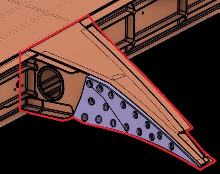
3.2 The product: left wingbox of an aircraft 28
3.3 The wingbox assembly process and resources 32
3.3.1 Stage 0: Components preparation 33
3.3.2 Stage 1: Main assembly 35
3.3.3 Stage 2: Spar riveting 36
3.3.4 Stage 3: Ribs and panels riveting and closure 36
3.3.5 Stage 4: Aerodynamic surfaces assembly and final tests 37
3.4 MfM methodology using 3DExperience 38
3.4.1 3DExperience basics 383.4.2 3DExperience as PLM 39
3.4.3 3DExperience as process planning software 39
4 Summary, conclusions and future research 57
4.1 Summary 57
4.2 Conclusions 59
4.3 Future research 59
References 60
Appendix A: Behavior Diagrams 62
Appendix B: Resumen ampliado en español 64
1. Introducción 64
2. La metodología MfM 65
3. Construcción de la capa de Ontología 66
4. Caso práctico: Diseño y planificación de una línea de ensamblaje aeronáutico 71
5. Conclusiones 74
6. Trabajos futuros 74LIST OF FIGURES Figure 1. 3-Layers Model (3LM) 4 Figure 2. IDEF0 diagram example 5 Figure 3. Concept maps example made using CMap tools (left) and DOT programming (right) 6 Figure 4. IDEF0 building block. 10 Figure 5. Top Level IDEF0 diagram 11 Figure 6. First level IDEF0 diagram, A0: ‘Design the Assembly Line.’ 11 Figure 7. IDEF0 diagram A1: ‘Define As-Planned.’ 12 Figure 8. IDEF0 diagram A2: ‘Define As-Prepared.’ 12 Figure 9. IDEF0 diagram A21: ‘Define Assembly Line.’ 13 Figure 10. IDEF0 diagram A22: Assign resources 13 Figure 11. IDEF0 diagrams hierarchy overview 14 Figure 12. DOT script defining the data model. 15 Figure 13. Concept map for the Data model, compiled from the DOT script. 16 Figure 14. As-Designed definition of the Data model 17 Figure 15. As-Planned definition of the Data model 17 Figure 16. As-Prepared Definition of the Data model 18 Figure 17. Feasibility and Balancing of the Data model 19 Figure 18. CMap Example 19 Figure 19. Enriched data model using DOT 20 Figure 20. Example of Data model instance. 21 Figure 21. Example of Data model instance: detail of As-Designed and As-Planned. 21 Figure 22. Example of Data model instance: detail of As-Prepared. 22 Figure 23. Behavior diagram basic example 23 Figure 24. Behavior diagram for activity “A12 Define the Assembly Sequence.” 24 Figure 25. Behavior diagram for activity “A211 Define Operations.” 25 Figure 26. Behavior diagram for activity “A213 Analyze Operations Feasibility.” 25 Figure 27. Left wingbox 3D view (courtesy by Nogales [16]). 28 Figure 28.Top panel overview and its mechanical unions (red) (courtesy by Nogales [16]) 28 Figure 29. Manhole access example (courtesy by Nogales [16]). 29 Figure 30. Bottom panel overview and its unions (red) (courtesy by Nogales [16]) 29 Figure 31. Front spar (courtesy by Nogales [16]) 29 Figure 32. Rear Spar (courtesy by Nogales [16]) 29 Figure 33. Box insides (courtesy by Nogales [16]). 30 Figure 34. Wingtip Rib detail (courtesy by Nogales [16]). 30 Figure 35. Trusses on the Bottom panel (courtesy by Nogales [16]). 31 Figure 36. Flap fairing (courtesy by Nogales [16]). 31 Figure 37. A400M HTP assembly (courtesy by Benasuly [17]). 32
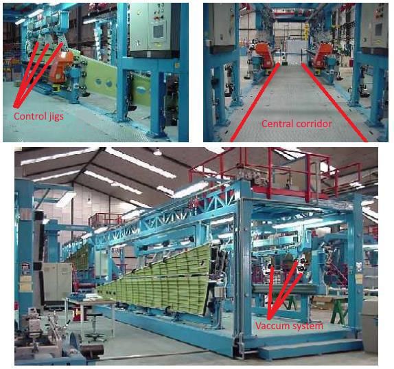
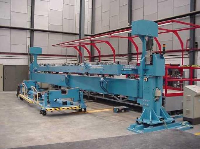
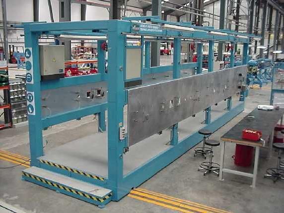
Figure 38. Panels tooling station detail (courtesy by Benasuly [17]). 33
Figure 39. Panels tooling station (courtesy by Benasuly [17]). 34
Figure 40. Spar tooling station (courtesy by Benasuly [17]). 34
Figure 41. Stage 1 tooling station main frame (upper left), mounted bottom panel (upper right) and blades
detail (down) (courtesy by Benasuly [17]). 35
Figure 42. Stage 2 tooling station (courtesy by Benasuly [17]). 36
Figure 43. Stage 3 tooling station (courtesy by Benasuly [17]). 36
Figure 44. FOD detection tooling machine (courtesy by Benasuly [17]). 37
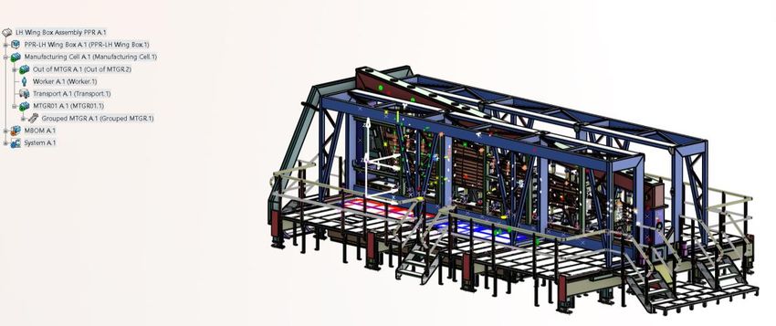
Figure 45. 3DX main groups 38
Figure 46. PPSR Tree. 40
Figure 47. Scope link clarification. 41
Figure 48. As-Planned close-up. 42
Figure 49. Full MBOM. 43
Figure 50. MBOM detail. 43
Figure 51. As-Prepared close-up. 44
Figure 52. Process planning elements. 45
Figure 53. Operation creation detail. 46
Figure 54. Equipment Allocation tooling overview. 46
Figure 55. Workload balancing tool. 47
Figure 56.As-Planned behavior diagrams: MBOM (A11, up) and Assembly Sequence definition (A12, down)
48
Figure 57. Manufacturing tile (and types) command 49
Figure 58. Scope link definition command. 49
Figure 59. Assignment Manager command and interface. 50
Figure 60.Precendence constraint command. 51
Figure 61. A211 and A212 behavior diagrams 52
Figure 62. Workplan creation command. 52
Figure 63. Operation creation command. 53
Figure 64. From left to right, Product Flow, Precedence Link, and Tree Reordering commands. 53
Figure 65. Analysis tools. From left to right, Time Analysis, Workload Balancing, and Premises Usage. 54
Figure 66. A221 behavior diagram. 54
Figure 67. Resource tyopes insertion commands and other useful ones. 55
Figure 68. Resource Analysis tools. 56
Figure 69. Behavior diagram for activity “A3 Generate Documentation.” 62
Figure 70. Behavior diagram for activity “A222 Define Industrial Means.” 62
Figure 71. Behavior diagram for activity “A223 Assign Workers.” 63
Figure 72. Behavior diagram for activity “A224 Analyze Resources Feasibility.” 631 INTRODUCTION
Manufacturing is more than just putting parts together. It’s coming up with ideas, testing
principles and perfecting the engineering as well as final assembly.
- James Dyson -
T
his chapter introduces the Model-Based Systems Engineering (MBSE) concept, and its implications in
the industry. Besides, the Ontology concept and a brief state of art are developed, in order to provide
some context in which Models for Manufacturing (MfM) is originated. This methodology is then
developed, focusing on the three-layer model (3LM) and its different components. Finally, prior 3LM
approaches are acknowkedged.
1.1 Model-Based Systems Engineering (MBSE)
According to Ramos et al. [2], Model-Based Systems Engineering “is an emerging approach in the Systems
Engineering (SE) field and can be described as the formalized application of modeling principles, methods,
languages, and tools to the entire lifecycle of large, complex, interdisciplinary, sociotechnical systems.” A
simpler definition is provided by Mellor et al. [3] as “...is simply the notion that we can construct a model of a
system that we can transform into the real thing.”. This model-centered approach, which main asset is
(usually) a 3D model of the system being developed, contrasts with the traditional document-based
methodology. This paradigm shift in how modelling is being made was possible thanks to the emergence and
quick improvement of computers. MBSE is currently being applied to several engineering disciplines, from
mechanical to electrical, and specially to complex, multidisciplinary projects, such as those accomplished in
automotive or aeronautical industries.
Ramos et al. [2] also assures that “In the next decade, it is expected that MBSE will play an increasing role in
the practice of SE and that will extend its application modeling domains beyond hardware and software
systems, including social, economical, environmental, and human-performance components.”
MBSE is a methodology that has got more and more important over the past decade and continues to be
improved nowadays. One of the main goals of MBSE is to substitute the classic 3D-centric approach and
document-oriented information in favor of a simulated model-oriented definition that has several advantages:
• The model is the core of the development, in terms of requisites, design, and manufacturing.
• Ability to manage complexity and to capture knowledge.
• Analysis and trade-off and early detection of issues.2
Introduction
• Keep consistency between requisites along the lifecycle.
• Allow flexibility when changes appear.
All in all, it could be said that this model-based approach, unlike the document-based one, allows a much
higher level of communication and collaboration between stakeholders and team members, improves design
precision and integrity avoiding potential data loss, grants better information traceability, and greatly reduces
development risks.
Hence, MBSE is an attempt to store the Company knowledge about a specific project into a model, rather than
documents, with the cited benefits that this implies. The main disadvantages of this concept are that models are
usually developed within a specific software framework, and thus are limited and dependent to the software
provider, and that they are also usually made individually for a specific project, not being easily applied to
other projects of similar areas. These issues have caused the apparition of the three-layer model (3LM) concept
among Models for Manufacturing, which will be detailed later.
1.2 Ontologies
In computer science and information science, an ontology encompasses a representation, formal naming and
definition of the categories, properties and relations between the concepts, data and entities that substantiate
one, many or all domains of discourse. More simply, an ontology is a way of showing the properties of a
subject area and how they are related, by defining a set of concepts and categories that represent the subject.
Ontologies are, thus, in the core of MBSE methodology. According to Uschold and Gruninger [4], ontology is
the term used to refer to the shared understanding of some domain of interest which embodies some sort of
world view with respect to the given domain.
Every academic discipline or field creates ontologies to limit its complexity and organize data into information
and knowledge. New ontologies help to improve problem solving within that domain.
Ontology model development is today a global research topic and ontology engineering (also known as
ontology building) refers to the set of tasks related to the ontology development process and the ontology
lifecycle, the methods and methodologies for building ontologies, and the tool suites and languages that
support them.
It aims to make explicit the knowledge contained in software applications, and organizational procedures for a
particular domain. Ontology engineering offers a direction for overcoming semantic obstacles, such as those
related to the definitions of business terms and software classes.
In order to assist in the creation, modification or manipulation of ontologies, specific applications, known as
ontology editors, have been developed. They commonly use one or several ontology languages, such as OWL
(Ontology Web Language).
Cited languages are not always intuitive and easy to work with form scratch. So as to be able to fulfil this
project, other applications have been used to make the modelling, such as RAMUS, for IDEF0 diagrams, or
CMAP Tools for concept maps. This model will then be converted into an ontology language, such as the
previously stated OWL. Cited halfway software tools will be treated in depth in the following pages, looking
into both functioning and worthiness points of view.
21.3 MBSE Initiatives for manufacturing MBSE has been globally accepted by the aerospace and automotive industry during the last few years, with lots of development and deployment in the Functional Design processes, specially emphasized in the area of systems design. Several research, developments, deployments, and projects has been conducted using MBSE, but only recently the interest is also being redirected to manufacturing. Industrial Design of the product, manufacturing and assembly, balancing lines, resources, configuration and change management, and many other tasks performed during the serial production phase of the lifecycle are now taking the attention of the researchers. The following lines collect some of the first initiatives for such application. Bergenthal [5] defines MBE (Model Based Engineering) in the Model Based Engineering final report for US NDIA (National Defense Industrial Association): “an approach to engineering that uses models as an integral part of the technical baseline that includes the requirements, analysis, design, implementation, and verification of a capability, system, and product throughout the lifecycle ”, already including the manufacturing side of the lifecycle into the MBSE concept. Friedenthal et al. [6] proposed a 2010 status and a 2020 vision on MBSE. Some topics selected for the 2020 vision are applied to manufacturing: • Extends to domains beyond engineering to support complex areas. • Enable the engineer to focus on abstract modeling of the user domain. • Modeling standards supporting high fidelity simulation and real representations. • Extensive reuse of model libraries, taxonomies, and design patterns. • Standards supporting integration and management across a distributed repository. Kulvatunyou et al. [7] present several ontologies for industrial problems that have been a topic of research for several years, most of the projects in the EU Horizon 2020 program have adopted ontology as a component and similarly, in the US NIST (National Institute of Standards and Technology), manufacturing projects also have ontology as a component. Actually, it reinforces the concept of commonality between the ontologies, long term interoperability between the different engineering, manufacturing, and supply chain disciplines. NIST [8] organized a workshop to explore the idea of a framework for curating ontologies, an IOF (Industrial Ontologies Foundry). The goal for the workshop was to identify industry needs, to develop consensus and to identify the issues that need to be addressed to move forward. Workshop participants reported the main reason in seeing an industrial ontology foundry is interoperability, information linking, and formalization of requirements through information constraints, incorporation of business process aspects, and quality and traceability. Several authors are researching on the development and deployment of MBSE methodologies and tools in manufacturing. Aspects like process planning, human resources, robotics, IoT (Internet of Things) among others are recently research topics.
4
                                                                                                  Introduction

1.4 Models for Manufacturing (MfM) Methodology
1.4.1   3-Layers Model (3LM)
Model-Based for Manufacturing methodology proposed is based on a 3-Layers Model, as shown in Figure 1.
The 3LM ensures the independence between layers, maintaining both Data Layer and Ontology Layer
isolated. This ensures the definition of the Ontology, the knowledge of the Company, is being made without
interacting with Data and Services layer. Therefore, the 3LM decouples the traditional system developed by
the software vendors allowing users to change software providers inside the Service Layer easily. All the
Company knowledge can be safely stored and used no matter which software is being used, granting a huge
flexibility and interoperability to the whole model.

                                      Figure 1. 3-Layers Model (3LM)
The bottom layer, Data layer, collect all the databases and interfaces: legacy databases from the legacy
software, databases from the commercial software applications, clouds, and many others. Included in the Data
layer are those databases to hold the information instanced using Ontology layer.
The central layer, the Ontology layer, is the core of the model. It holds all the Company processes and scope,
data and semantic models, and the associated simulation or behavior requirements. Given its crucial
importance, this work will be focused on the development of such layer, digging into the definition of every of
its components, and leaving both Data and Service layer to future research. These Ontology building tasks will
be carried out using the Ontology editor apps introduced before in Section 1.2.
The top layer, Service layer, holds the software services, such as authoring and simulation tools, visualizers,
data analytics and dashboard and space design exploration tools. Services are used thanks to information
stored in the Data layer, instanced through the Ontology layer.

1.4.2   Ontology layer
Modelling what a Company knows about any subject is not an easy task, due to its enormous complexity and
degree of abstraction. In order to properly store knowledge, four main components are going to be created
within the Ontology model: Scope model, which aims to define the Ontology framework and its rules; Data
model, which collects all the different concepts known by the Company, as well as how these concepts are
connected between each other; Behavior model, giving concepts and relations its dynamic character and
evolution in time, and Semantic model, so as to ensure a common glossary of technical definitions avoiding
misunderstandings caused by polysemic words and different interpretations of language.

                                                      4
1.4.3 Scope model
As has been stated before, the Ontology layer stores all the Company knowledge in a given field of study, and
it is what adds value to the whole model. In order to build an Ontology about any domain, the very first step is
to clearly define its scope, i.e., to decide which are going to be the limits and degree of detail for the contents
of the Ontology. This ensures that every stakeholder works within a common framework when carrying out
the Ontology engineering process and avoids running into a common issue known as feature creep, which
would be best called in this case detail creep.
In this project, the scope model definition has been made using IDEF0 diagrams. This kind of representation
allows a simple, clean model, easy to understand at first glance, which has been proved very useful when
making changes and powerful enough for a preliminar study in Ontology building techniques. An IDEF0
diagram is shown in Figure 2 for clarification.
Figure 2. IDEF0 diagram example
The chosen Ontology editor to create such diagrams is RAMUS, in its educational version. The main reasons
for this choice are its user-friendly, easy to exploit behavior, the ability to export these diagrams into
IDL(Interactive Data Language) code, which is a text format. These text files would then be converted and
interpreted by a PLM software, Aras for instance. Once the PLM model is created, it would be the starting
point so as to develop Data model, via OWL exportation.
As said before, RAMUS is good enough for a first approach of how to build an Ontology for an academical
exercise, being this and next editor tools shown likely to change for more advanced and complex ones if trying
to manage a real scenario. IDEF0 diagrams and RAMUS use will be explained in detail in its own chapter.
It is worth remarking the highly iterative character of the scope definition process. The scope model has
suffered several major modifications, from its very first conception to its final configuration. It has been
involved in a continuous improvement process, always trying to best capture details and issues which are
needed to be considered. It has been going through these iterations when having simple and easily
understandable models made with a manageable app has shown its huge value.6
Introduction
1.4.4 Data model
Next step in building any Ontology is creating what is called the Data model (do not mistake for Data layer).
Once the scope of the Ontology is completely defined, the process of storing the information within the
Ontology itself can begin. Usually, the most common technique for such task is via graphical representations,
i. e., making use of graph theory, specifically using concept maps. This way, different concepts are stored
inside shapes, and then relations between them are added using arrows connecting cited shapes. Usually, a
connector (commonly a verb) is placed near the arrows to give more information about the relations’ nature.
For this representation to be effective, a prior meaning code of shapes, colors and arrows must be specified.
Further explanation of concept maps and meaning code decisions will be presented on following pages.
This work first used CMap tools as its editor app for carrying out the Data model definition. As explained
previously with RAMUS, the reasons behind this choice were its simplicity, ease for interconnection and its
export/import capability in text format. However, although proved very useful in presenting final results,
making diagrams neater and more visually attractive, CMap tools really lacks an efficient way to make
important changes in the Data model. As can easily be foreseen, lots of iteration in scope model came
unavoidably with a great amount of changes in Data model.
So as to speed up the iteration process, another editor app was considered. Instead of making use of a visual
GUI, based on drag and drop mechanisms, such as CMap tools, DOT is a text-based graph description
language . Just by typing some simple scripts, as could happen when programming any auxiliar gizmo, DOT is
able to compile concept maps with ease, allowing even some customization for shapes, colors, and arrows
behavior. Due to its versatility and quick response for modifications, it is worth a try.
Concept maps using both apps are shown in Figure 3.
Figure 3. Concept maps example made using CMap tools (left) and DOT programming (right)
In a similar way as what has already been stated in scope model, it can be noted the large number of iterations
that have been necessary before reaching the final configuration for the Data model. Again, this has been made
to ensure that all possible features and potential issues are being considered, and so the model is as robust as
possible.
Once Data model is first created (using some objects from the Scope Model), it can be developed in more
detail. It is said that the Data model is being enriched with new information, adding it as much as desired,
taking into account that the whole model should not encompass more than what was previously agreed on the
scope model.
This enrichment process is based on adding new auxiliary or secondary concepts, which were not so important
to define data model itself but can help describing it in depth. Besides, both former and new concepts are given
what are called attributes. These are a list of properties unique of each concept and are also used to better
6define the latter ones. Attributes have their own code inside de concept map diagrams, and due to software variations, they are also represented differently on CMap tools and DOT (see Figure 3). Data model building and enriching will be shown in more detail in its own chapter, giving a use case as an example of a specific instanciation of the model for better visualization of its practical applicability. 1.4.5 Behavior model Data model groups lots of concepts and its relations in order to store the Company knowledge. However, those concepts and causal relations need to be sorted via some criteria. For example, when thinking of an assembly procedure, besides knowing which parts need to be assembled and their relativc position, it is mandatory knowing the assembly secuence, this is, the assembly timeline, and exactly how the different assembly operations are carried out. These sort of “whens” and “hows”, among other aspects, are collected in the behavior model. It essentially stores how every concept and relation inside Data model behaves, both with itself and others. Thus, behavior model must be an evolved data model, and have the latter as a point of start. Different approaches were made so as to get a behavior model that while simple and easily understandable, would be also able to fulfill the objectives set for it, explained previously. The final representation adopted is what will be called a behavior diagram to embody the requirements of the behavior model. Behavior diagrams are modeled with the same software tool DOT that has been used for the concept maps of the Data Model. A more in depth of these diagrams and how to build them is given on Section 2.3. 1.4.6 Semantic model Last but not least, a semantic model is needed when building an Ontology. As has been explained before, the main objective in Ontology building is preserving the Company knowledge and being able to use it wherever the place by whomever. In order to ensure that, it is essential to develop a common language, so that every team member using this Ontology has the same concept and definition when talking about any subject. Semantic model aims to achieve a total agreement between stakeholders, preventing future misunderstandings from happening and ensuring that a common semantic framework is being used. The development of this model is out of the scope of this work and should be considered in future research so as to complete the Ontology modelling. 1.4.7 State of the art of MfM methodology In the last few years, several authors have applied the 3LM methodology, with varying depth and complexity, to a number of use cases. These preliminary results are being used to refine and deepen 3LM, so as to be able to apply this method to more complex and realistic scenarios. Even before the 3LM concept was first sketched, Mas et al. [9] pointed the necessity of process-based models, capable of being applied during the whole product lifecycle. These very first steps were made using the Unified Modelling Language (UML), and set the foundations to the actual 3LM method. Mas et al. [10] first introduced the 3LM methodology, stating the MBSE applicability situation and the objectives presented in this project. The three different layers, their behavior and tightness were first defined, as a solution for the software interoperability issues and aiming to achieve an independent ontology for the Company. As well as this project will do, it focused on the ontology layer, briefly defining its components, and discussing the best way to model them. Following this current of thought, Rizzi [11] proposed concept maps as the first step in an ontology construction method. Austin [12] explores different mechanisms and diagrams in order to model behavior, and Szejka [13] comes with a preliminary method to develop semantic interoperability in MfM. Some of said ontology construction methods, as well as other self-developed ones will be used in this project to build the ontology model for 3LM. Finally, some early versions of 3LM have been already applied to simple engineering use cases. Morales- Palma et al. [14] have made use of the methodology to study incremental sheet forming processes, specifically applying it to Single-Point Incremental Forming (SPIF). Mas et al. 2019 [15] applies this same methodology to assembly lines in Airbus, mainly on Final Assembly Lines (FAL). Their results, while very academic and
8
                                                                                                  Introduction

idealistic, are proof of validity for the methodology concept, and show the great versatility of the method
developed.
In order to enlarge this versatility, the present work will apply 3LM to another scenario, concerning a
subassembly of a big elemental, such as a wing box, prior to its integration inside the FAL. This will be shown
as an example of an instanced model, once the ontology is built, and should be contained in the Data Layer and
available for the Service Layer to be exploited regardless which software would be used. Said interaction
between layers is yet to be implemented and should be developed within further projects.

                                                      8
2 3LM ONTOLOGY LAYER BUILDING PROCESS
Engineering or technology is the making of things that did not previously exist,
whereas science is the discovering of things that have long existed.
- David Billington -
T
his chapter presents the Ontology building process for the aeronautical assembly process, from the scope
definition to the behavior modelling, going through the Data model definition and enrichment. For each
model, the selected diagram type is presented along with the specific software used to draw the
graphical models. Examples selected to describe the building process of the ontology layer belong to the
aeronautical assembly use case and will be presented in the next chapter.
2.1 Scope Model using IDEF0 Diagrams
As has been said previously, the very first step when building an Ontology is defining its scope. This allows to
stablish a preliminar framework and clarify the Ontology’s boundaries so as to limit the project’s degree of
detail. Due to its numerous advantages as far as versatility and adaptability are concerned, previously stated,
IDEF0 diagrams have been chosen in order to model scope model.
IDEF0(‘Icam DEFinition for Function Modeling’, where ICAM is an acronym for ‘Integrated Computer
Aided Manufacturing’), is a function modeling methodology for describing manufacturing functions, which
offers a functional modeling language for the analysis, development, reengineering, and integration of
information systems; business processes; or software engineering analysis.IDEF0 is part of the IDEF family of
modeling languages in the field of software engineering, and is built on the functional modeling language
Structured Analysis and Design Technique (SADT).
IDEF0 may be used to model a wide variety of automated and non-automated systems. For new systems, it
may be used first to define the requirements and specify the functions, and then to design an implementation
that meets the requirements and performs the functions. This is the case of this work, in which a new Ontology
is being built. Besides, for existing systems, IDEF0 can be used to analyze the functions the system performs
and to record the mechanisms (means) by which these are done.10
3LM Ontology layer building process
2.1.1 IDEF0 building blocks
The result of applying IDEF0 to a system is a model that consists of a hierarchical series of diagrams which
are interrelated. The two primary modeling components are functions (represented on a diagram by boxes) and
the data and objects that connect those functions (represented by arrows).
Figure 4. IDEF0 building block.
Figure 4 shows a single block, in which a Function is represented in the middle and one of each type of data
connect it. Each activity is described by a verb-based label placed in a box.
Coming from the left, inputs feed the Function. These are data that are used by the function in order to produce
the output, being transformed throughout the process.
On the upper section come the control elements. These are objects that help when specifying how the inputs
turn into outputs, and they remain unaltered during this transformation.
Coming from the bottom part there is the mechanism arrow. As is clarified in the figure itself, this kind of data
are the resources used in order to produce the outputs. These can be industrial, manufacturing, human or
software resources, among others.
The logical output is shown as an exiting arrow on the right side, which will then feed the next block or blocks.
These are new data generated by the function using all prior objects.
The IDEF0 process starts with the identification of the prime function to be decomposed. This function is
identified on a “Top Level Context Diagram,” that defines the scope of the particular IDEF0 analysis. From
this diagram lower-level diagrams are generated. So as to be able to quickly identify the function’s hierarchy, a
coded number is given to each one.
2.1.2 Software for IDEF0 diagrams: RAMUS
The selected tool to create IDEF0 diagrams is RAMUS. Its educational version offers a simple and open-
source software. It is really intuitive and easy to use, elements are inserted with a single command, and so are
the arrows between them.
Both Top Level and “child” diagrams are shown in the full IDEF0 anaylisis made on the wingbox assembly
case of use, Figure 5-10.
10Figure 5. Top Level IDEF0 diagram
Figure 6. First level IDEF0 diagram, A0: ‘Design the Assembly Line.’
In order to design an assembly line (see Figure 5 and 6), having the As-Design as a beginning point, and taking
into account the Company know-how and customer specifications, as well as the Company resources
(Manufacturing, CAx software and Quality management) As-Planned and As-Prepared need to be planified.
Other parallel activities need to be done, such as generate respective documentation or send change requests in
case any issues are detected.12
3LM Ontology layer building process
Figure 7. IDEF0 diagram A1: ‘Define As-Planned.’
As-Planned is modelled with two main tasks, as can be seen in Figure 7: defining the manufacturing bill of
material (MBOM) and the assembly sequence, conditioned by the change request proposal, if triggered.
Figure 8. IDEF0 diagram A2: ‘Define As-Prepared.’
12Figure 9. IDEF0 diagram A21: ‘Define Assembly Line.’
As-Prepared uses As-Planned and the assembly manuals to define the assembly line, its resources and its
balancing, as depicted in Figure 8. These also produces the change request proposal. The assembly line is built
defining the different manufacturing operations (see Figure 9), that are then grouped in several stations, which
need to be configured and sorted. Besides, feasibility need to be analyzed, both operation and station-level,
being important in determining the change request conditions. Every of these is again conditioned by the
possibility of a former change request trigger.
Figure 10. IDEF0 diagram A22: Assign resources14
3LM Ontology layer building process
Resource assignment is made defining each of the different resources (see Figure 10), i. e., Jigs&Tools,
industrial means and workers, as well as determining their requirements. Feasibility of these requirements is
again needed, being a key factor when launching a change request.
As can be seen in Figures Figure 5-10, a detailed scope and boundaries are defined for the practical case
presented. Transformation processes, resource and control definition, and feedback mechanisms are presented.
In order to better clarify the hierarchy between diagrams, Figure 11 presents an overview of all IDEF0
diagrams.
Figure 11. IDEF0 diagrams hierarchy overview
142.2 Data Model using Concept maps
Once the scope is set, the next step is building the Ontology core, that is, the Data model. All the Company
knowledge is now embodied into the Ontology, via several general concepts and their relations between each
other.
Because of the desired structure for the Data model, concept maps are chosen as the most suitable option.
These diagrams have the same structure as the one pursued in Data model and are easily understandable by
anyone no matter its relationship with the Company, nor its previous knowledge about ontologies.
2.2.1 Software for concept maps: CMap Tools and Graphviz DOT
As has been said before, two different approaches were made when building the Data model, due to major
differences between the two software tools used. At first, CMap Tools was used. Its drag&drop behavior is
intuitive and user friendly, and the results achieved are consistent and visually attractive when developing a
simple model. The first disadvantage found is its lack of agility when working between iterations. This
induced the use of DOT library in Notepad++. DOT is a text-based graphical tool, i.e., the graphs are
automatically generated from a text code with the corresponding instructions. While results are still pretty
good, its usage is much more advanced. Using DOT means losing some flexibility in the final diagram, in
exchange of a much more powerful tool making changes rapidly between iterations.
This complementary character between both tools makes them ideal for its serial exploit. First, DOT is used to
go through iterations until reaching the desired configuration. Then, so as to present the final result in a prettier
way, CMap Tools is used.
DOT needs the user to be familiarized with its language. Once the specific commands are learned, its usage is
as simple as typing the desired structure for the diagram onto a text file and then compiled and executed by
DOT. Therefore, just rearranging code and executing it again lots of diagram variants can be generated
immediately, being now remarkable the great value of this tool when iterating the model. One example of
DOT scripting and its result can be seen in Figure 12 and Figure 13.
Figure 12. DOT script defining the data model.16
3LM Ontology layer building process
Figure 13. Concept map for the Data model, compiled from the DOT script.
As can be seen, there is some loss of flexibility, since arrows are automatically connected and cannot be
rerouted, but results are quite good. As well as CMap, DOT has some customization features, such as
independent background colors for subsections or box coloring, which will be shown in the model enrichment
point.
The model presented is divided in four different sections, which mostly match the main activities previously
shown in IDEF0 main diagrams. These are As-Designed, As-Planned and As-Prepared definition, and an extra
module named as Feasibility and Balancing.
16Figure 14. As-Designed definition of the Data model
As-Designed definition process is shown in Figure 14. It is an object made of the Engineering Bill of Material
(EBOM), the Assembly Manuals needed to sort said EBOM, and the parts themselves constituting the final
product. How these items are related is explained over the concept map itself.
Figure 15. As-Planned definition of the Data model
As-Planned (Figure 15) is even simpler, at least by itself. It is just the sum of the Manufacturing Bill of
Material (MBOM), obtained from the EBOM, and the Manufacturing Sequence used to carry out the
Assembly.18
3LM Ontology layer building process
Figure 16. As-Prepared Definition of the Data model
As-Prepared (Figure 16) can be a bit more complex, due to the variety of objects involved. As-Prepared
embodies all different operations made in order to fulfill the Assembly process. These operations are grouped
in stations. The final sorted set of stations constitute the final assembly line. Both operations and stations are
responsible for defining the resource requirements, that is, which specific investments are needed to be done so
as to perform the different assembly steps. Resources have been grouped in three different categories:
Jigs&Tools, Workers (manpower) and Industrial means.
18Figure 17. Feasibility and Balancing of the Data model
As have been said before, one extra module was needed to complete the whole concept map. This is the
Feasibility and Balancing one (Figure 17). As can be seen, it is really simple, and is used only to ensure that
change requests are triggered, and thus, iterations are made during the assembly line definition development.
Change requests can be triggered due to issues regarding the line evaluation itself (non-feasible operations or
sequences because of ergonomic reasons, for example) or due to balancing aspects (changing some operations
or switching sequences may improve assembly time, for instance).
All these sections presented before are not self-isolated, but connected between each other, so that each
different module feeds the other. The whole concept map has been presented in Figure 13.
CMap tools is, as said before and mainly, easy to use. When opening a new project, it is very fast to introduce
the several concept boxes, and so is connecting them using arrows. Blanks are automatically placed and then
easily filled. Once every single object is created, they can be rearranged simply by dragging and dropping
them in the desired locations.
Some customization options are available, such as changing boxes color and outline, arrows type, text font and
size or background color for diferenciating sections. An early diagram is shown in Figure 18.
Figure 18. CMap Example20
3LM Ontology layer building process
2.2.2 Data Model enrichment
The presented Data model is then completed and detailed, introducing new concepts and giving attributes to
concepts. This allows a better and deeper definition of the model. A special codification is used to be able to
differentiate between former and new elements: new boxes will be introduced in yellow. When using DOT,
attributes will be implemented inside concept boxes, separated by a horizontal divider. Using Cmaps,
attributes will be recognized because they are not enclosed in a box. An enriched model for clarification is
shown in Figure 19. Said model is made using DOT and corresponds to the same practical case presented
before, an aeronautical assembly line design.
Figure 19. Enriched data model using DOT
20Figure 19 shows the basic Data model structure for the said case, shared with the scope model already
presented in 2.1. As-Designed, As-Planned and As-Prepared are located in different sections and related
between each other, and also conditioned by the Feasibility and Balancing section, responsible for triggering a
possible change request. Several “child” concepts hang from each of them. New concepts and attributes are
introduced following the new codification. For instance, now the manufacturing sequence is described a little
further, introducing the concept of manufacturing steps. In a similar way, the different stations are now made
of assembly procedures, which properly arrange operations. Both new and previous concepts have some key
properties, such as total time invested during an assembly procedure, or the manufacturing part type (bough -
off the shelf- or made). It can be seen that the arrangement is not the best aesthetically speaking. This justifies
the use of CMap for the final result.
2.2.3 Data Model instancing simulation
So as to exemplify how different layers inside the 3LM would work, an instancing simulation is presented.
Enriched data model shown in 2.2.2 would feed the Data layer via legacy applications or interfaces. Once this
model is stored in the database, it can be automatically filled with concepts and attributes specific of a case of
use. The filled diagram for a specific practical case is called an instance. Taking the wingbox assembly case as
an example, the resulting instance that would be processed by the Data layer is shown in Figure 20
Figure 20. Example of Data model instance.
Figure 21. Example of Data model instance: detail of As-Designed and As-Planned.22
3LM Ontology layer building process
Figure 22. Example of Data model instance: detail of As-Prepared.
Figures Figure 20-Figure 22 show the full instanced model. The previous structure is now filled with specific
data: each part and subasembblies are defined, as well as each manufacturing step, operation, station,
procedure and resource requierement. Numerical values are given for the suitable attributes, such as the time
needed to perform each operation. Other attribute fields are also filled. Feasibility and Balancing attributes
have not been changed due to the impossibility of computing such analysis, but would return a Boolean value,
and may or may not define and trigger a change request proposal. Theoretical concepts (the ones shown in
Figure 19) are still present, marked between brackets.
For further clarification, some key concepts and their relationships are going to be described. Taking a look to
the As Designed section, now it is the product itself (wing box) the concept in the box. Similarly, now parts are
instanced, being noted as P01, P03 and P05. Each one is then defined via its name attribute (Panels, Spars and
Ribs, respectively). P02 and P04 are used to instanciate the different subassemblies, that is, the joining of two
parts.
Another good place to look is the assembly line section. Here, a single line made of a single station approach
has been made. Inside this station, two different procedures are carried out, one after the other. The first one,
denoted as pc1, is defined using its attributes, that is, its name, which clarifies what this procedure is about, and
the total time needed in order to fulfil it, which is the sum of the times of every operation made inside the
procedure. In this case, pc1 aims to join panels and spars of the wingbox, and is made of operations O11, O12,
O13, O14, and O15. In the same way, these operations also are defined via their names and times, stored on
their properties. Once pc1 is finished, pc2 can begin, joining ribs to the subassembly resulting of pc1. Its
structure is very similar to the one explained for pc1 and thus is omitted. For simplicity, and just to exemplify
and instancing process, non-productive times have not been considered, and numerical values have been
estimated vaguely.
It is worth noting that this example was specifically chosen to be extremely simple and clear so that concepts
could be easily understandable. On a real case the huge amount of parts and operations would make it difficult
to apprehend everything at a glance.
22You can also read