Evolving Architectures and Considerations to address Distributed Energy Resources and Non-Wired Alternatives - July 2021
←
→
Page content transcription
If your browser does not render page correctly, please read the page content below
PNNL-31751

Evolving Architectures and
Considerations to address Distributed
Energy Resources and Non-Wired
Alternatives
July 2021

Subramanian (Mani) Vadari

DISCLAIMER

This report was prepared as an account of work sponsored by an agency of the
United States Government. Neither the United States Government nor any agency
thereof, nor Battelle Memorial Institute, nor any of their employees, makes any
warranty, express or implied, or assumes any legal liability or responsibility
for the accuracy, completeness, or usefulness of any information, apparatus,
product, or process disclosed, or represents that its use would not infringe
privately owned rights. Reference herein to any specific commercial product,
process, or service by trade name, trademark, manufacturer, or otherwise does not
necessarily constitute or imply its endorsement, recommendation, or favoring by
the United States Government or any agency thereof, or Battelle Memorial
Institute. The views and opinions of authors expressed herein do not necessarily
state or reflect those of the United States Government or any agency thereof.

            PACIFIC NORTHWEST NATIONAL LABORATORY
                               operated by
                              BATTELLE
                                  for the
              UNITED STATES DEPARTMENT OF ENERGY
                   under Contract DE-AC05-76RL01830

                         Printed in the United States of America

                    Available to DOE and DOE contractors from the
                     Office of Scientific and Technical Information,
                       P.O. Box 62, Oak Ridge, TN 37831-0062;
                                    ph: (865) 576-8401
                                   fax: (865) 576-5728
                          email: reports@adonis.osti.gov

         Available to the public from the National Technical Information Service
                        5301 Shawnee Rd., Alexandria, VA 22312
                                 ph: (800) 553-NTIS (6847)
              email: orders@ntis.gov
                        Online ordering: http://www.ntis.gov

                                                                                    1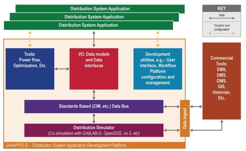
2
3
1.1 Executive Summary
The electric grid is in the beginning stage of a transformation, arguably the most significant in its history.
This transformation is driven by a combination of shutdowns of coal-fired plants, commissioning of new
natural-gas plants, and tremendous growth in energy supply from renewables, wind, and solar, based on
location. Regardless of this transformation, customer expectations for reliability, power quality, and
resiliency have only increased – customers want improved reliability and better power quality, supplied
by sustainable (green) energy sources through a resilient grid at the lowest possible cost. Even as these
expectations increase, grid reliability is threatened by increasingly erratic and severe weather events and
changing customer behavior of adding renewables and non-wires alternatives both on the grid and behind-
the-meter. As utilities navigate this transformation, their progress is supported by advances in Operational
Technologies (OT), and Informational Technologies (IT), such as automation, smart inverters, cloud
computing, mobile computing, machine learning, big data analytics, and others, which have the potential
to enable advanced capabilities more efficiently and at a lower cost. Finally, the industry is experiencing
new business entities like aggregators, community choice aggregation (CCA), microgrids, and others that
will interact with the grid in novel ways. There is another dimension to be considered here. In addition to
advanced solutions, the industry is at another tipping point where new technological architectures are
essential to managing grid complexity.
These changes will significantly affect transmission and distribution operations. Expected changes will
include (1) different system operators controlling segments of the system; (2) different sources of
active/reactive power supply ranging from transmission-located to rooftop solar-based, some of which
will be from renewable sources and could vary depending on solar/wind availability; (3) the ability to
dispatch sources of power supply versus ‘must take’ when available; (4) new cost models for this power
whether tariff-based or market-based; (5) adjusting how ancillary services are procured to ensure the grid
will still work reliably providing quality power to all. Continuing support for legacy technology
investments is required to enable this new future scenario. Along with cybersecurity and equity issues, the
future will require new architectural approaches for electric grid operations to tackle the rapidly evolving
requirements of the future electric grid.
This white paper focuses on the architectural considerations that will allow the industry to handle this
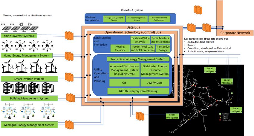
transition in a planned manner. It introduces and formalizes two architectural constructs –the data bus and
the control bus. The data bus is responsible for carrying all non-operational models and information
necessary to drive utility decisions. In contrast, the control bus is responsible for carrying all operational
data and control actions taken at the local level, centralized level, or other levels in-between, should they
exist. This separation was necessary to isolate data and actions that control the electric grid from getting
interspersed with other types of information exchange. These may already exist in today's architectures at
a conceptual level, but not as formal components. Both constructs are necessary to ensure that the most
efficient processing of information and control occurs at the proper location. The two buses also need to
work through a broad range of communications mechanisms and protocols and support all the systems
(e.g., centralized, decentralized, distributed, and non-utility).
The two buses are isolated by one or more security mechanisms, ensuring information transported by either
of them or their actions are not compromised. These buses are also supported by a combination of (1)
standards-based data structures, (2) standardized interfaces (i.e., Application Program Interfaces (APIs)),
(3) a standardized set of available services in the architecture, (4) standardized as-built and as-operated
models, all leading to (5) self-registration and provisioning of devices, applications, and systems on the
network. These support components apply to the buses, applications and devices on the power grid.
4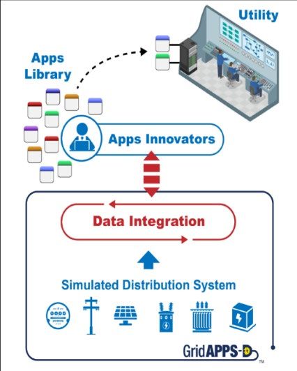
The future of reliable electricity supply relies on an information-rich environment where an increasing
amount of data will come from sensors on the electrical system and beyond (grid-edge and Behind-The-
Meter [BTM]). The data is often accompanied by its implicit patterns and behaviors, providing insights
into electric grid behavior. The overall architectures and systems implemented must evolve with these
changes. This white paper reviews those architectural considerations and provides a detailed perspective
on their requirements and how they will evolve.
This paper intends to provide a context for vendors, utilities, and their service providers to review and
understand the changes that are coming in the future and get ready for them. Each vendor and utility may
approach the journey in their own ways to stay competitive and ahead of the others. Still, we hope they
approach these changes using the constructs presented in this paper allowing for more seamless
interactions between the various stakeholders in the evolving marketplace and also to avoid their assets
from being stranded. .

                                                                                                           5
1.2 Acknowledgments
This paper would not have been possible without the input and support from the following:Industry
• Mr. James Walters – Exelon Corp.
• Mr. Kevin Fox – Duke Energy
• Mr. D. J. Harrison – Duke Energy
• Mr. Keith Hock – Ameren
• Mr. Young Ngo – Survalent
• Mr. John (JD) Hammerly – The Glarus Group and Modern Grid Solutions
• Ms. Anne Cleary – Modern Grid Solutions
• Dr. Avnaesh Jayantilal – GE Digital Grid
• Ms. May Millies – GE Digital Grid
• Mr. Sridhar Chandrashekar – Optio3, an IoT company
• Mr. Andrew Dicker – Accenture
• Mike Piechowski – Deloitte Consulting, LLP
• Christian Grant – Deloitte Consulting, LLP
• Rod Parry – Puget Sound Energy
• Kincheiu Wei – Puget Sound Energy
Academia
• Prof. Anjan Bose – Washington State University
• Prof. Anamika Dubey – Washington State University
National Labs
• Mr. James Ogle – Pacific Northwest National Laboratory
• Dr. Kevin Schneider – Pacific Northwest National Laboratory
• Dr. Ron Melton – Pacific Northwest National Laboratory
• Dr. Alexander Andersen – Pacific Northwest National Laboratory
• Mr. Jonathan Barr – Pacific Northwest National Laboratory
• Mr. Eric Andersen – Pacific Northwest National Laboratory
This work was done under the auspices of the GridAPPS-D™ project, a Department of Energy-
sponsored open-source software platform being developed for data integration and application
development. As a part of this project, the analysis of architectural considerations was needed to
ensure that today's architectures could transition to handle tomorrow's planning / operational
problems and situations.
61.3 About the GridAPPS-D™ project
This work was funded under the GridAPPS-D™ project. The United States (U.S.) Department of
Energy (DOE) Office of Electricity (OE), Advanced Grid Research sponsors the GridAPPS-D™ project,
which focuses on reducing time and cost to integrate advanced functionality into distribution operations
and create a more reliable and resilient grid. Under Pacific Northwest National Laboratory (PNNL)
leadership, the GridAPPS-D™ program has developed a reference open architecture environment
(platform) to support that objective.
What GridAPPS-D™ does
GridAPPS-D™ standardizes the data exchange interfaces between field devices, distributed
applications, and applications in the control room. With this standardization, information can
flow between systems that have historically been siloed. This creates "data fusion," where an
Advanced Distribution Management System (ADMS) can access all data through a common bus
(interface) across multiple applications and execute command functions, all using a common and
consistent power system model.
The GridAPPS-D™ platform uses a standards-based data model, logical data abstractions, and an
exchange mechanism to enable the development of portable applications easily deployable within
any operational environment that supports the GridAPPS-D™ programming model regardless of
the utility or vendor system.
The GridAPPS-D™ approach is based on the premise that the best approach to providing cost-
effective integration and enabling advanced control and coordination applications for a future
decarbonized distribution system is to move to a standards-based approach that uses open
Application Programming Interfaces (API's) and architectures.
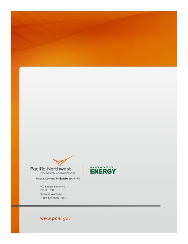
Figure 1: GridAPPS-D™ Architecture
The connection between GridAPPS-D™ and this white paper
GridAPPS-D™ is an open-source, standardized architecture and implementation approach for
power system applications targeted at a utility's planning and operations functions. Application
innovators and vendors can use it when developing their advanced applications for distribution
management to reduce cost and complexity while decreasing time to market. Still, reaching a
7successful outcome requires assessing the architectural needs of distribution operations and how
those needs evolve in the future in concert with ensuring legacy applications are still supported.
This white paper creates a bridge between the past (legacy architectures) and a future supporting
a broad range of operational needs.
81.4 Acronyms and Abbreviations
AC – Alternating Current IoT – Internet of Things
ADMS – Advanced Distribution Management IOU – Investor-Owned Utility
System
ISO – Independent System Operator
AGC – Automatic General Control
IT – Information Technology
AI/ML – Artificial Intelligence/Machine Leaning
ITMaaS – Information Technology Management
AMI – Advanced Metering Infrastructure as a Service
AMR – Automatic Meter Reading KVAR – Kilo-Volt Ampere Reactive
API – Application Programming Interface KW - Kilowatt
ARRA - American Recovery and Reinvestment MaaS – Managed software as a Service
Act of 2009
MBaaS – Mobile Backend as a Service
BESS – Battery Energy Storage System
MW - Megawatt
BMS – Building Management System
MWAR – Megawatt Amperes Reactive
BTM – Behind The Metering
MWFM – Mobile Work Force Management
BYOD – Bring Your Own Device
NAESB - North American Energy Standards
C&I – Commercial and Industrial (Load) Board
CAN – Controller Area Network (Bus) NERC – North American Electric Reliability
Council
CCA – Customer Choice Aggregate
NWA – Non-Wires Alternatives
CIM – Common Information Model
OMS – Outage Management System
CIP – Critical Infrastructure Protection
OpenADR – Open Automated Demand Response
CIS – Customer Information System
OpenFMB – Open Field Message Bus
D - Distribution
OT – Operations Technology
DaaS – Desktop as a Service
PaaS - Platform as a Service
DC – Direct Current
PCC – Point of Common Coupling
DCaaS – Data Center as a Service
PNNL – Pacific Northwest National Laboratory
DER – Distributed Energy Resources
PV – Photo-Voltaic
DERMS – Distributed Energy Resource
Management System PUC – Public Utilities Commission
DNP3 – Distributed Network Protocol REBA – Renewable Energy Buyers Alliance
DOE – Department of Energy REC – Renewable Energy Credits
DR – Demand Response REP – Retail Energy Provider
DSO -Distribution System Operator REST - REpresentational State Transfer
EMS – Energy Management System RTO – Regional Transmission Organization
ERCOT – Electricity Reliability Council of Texas SaaS – Software as a Service
9ERP – Enterprise Resource Planning SAP – System Application and Product in
Processing
ESB - Enterprise Services Bus
SCADA – Supervisory Control and Data
EV – Electric Vehicle
Acquisition
FERC – Federal Energy Regulatory Commission
SGIP - Smart Grid Interoperability Panel
FLISR – Fault Location Isolation and Service
SMB – Small and Medium Businesses
Restoration
SO – System Operator
GIS – Geospatial Information System
T – Transmission
GPS – Global Positioning System
TAC - Technology Application Center at the
HVAC – Heating Ventilation and Air Condition
University of Illinois
IaaS - Infrastructure as a Service
TOU – Time of Use
ICCP – Inter-Control Center Communications
UID – Universal Identifier
Protocol
VVO – Volt-VAR Optimization
IEEE – Institute of Electrical and Electronic
Engineers
101.5 Table of Contents
Executive Summary.................................................................................................................... 4
Acknowledgments ...................................................................................................................... 6
About the GridAPPS-D™ project .............................................................................................. 7
Acronyms and Abbreviations ..................................................................................................... 9
Table of Contents...................................................................................................................... 11
List of Figures........................................................................................................................... 13
Abstract..................................................................................................................................... 14
1. Introduction and setting the context ......................................................................................... 15
1.1. Utility structural constructs ...................................................................................................... 16
1.2. Utility transformation ............................................................................................................... 17
2. Participants and their impact on system operations .................................................................. 20
2.1. Vertically integrated utility....................................................................................................... 20
2.2. Regional Transmission Organizations, Independent System Operator (RTO/ISO) ................. 22
2.3. Community Choice Aggregation (CCA) .................................................................................. 22
2.4. Aggregators .............................................................................................................................. 23
2.5. Renewable Energy Buyers Alliance (REBA) ........................................................................... 24
2.6. Microgrid operator.................................................................................................................... 24
2.7. Customers installing renewables and non-wired alternative solutions on the grid................... 24
2.8. Public and commercial electric vehicle charging stations ........................................................ 25
2.9. Summary................................................................................................................................... 25
3. State of operational architectures and systems ......................................................................... 26
3.1. Core systems ............................................................................................................................. 27
3.1.1.Geospatial Information System................................................................................................ 29
3.1.2.Supervisory Control and Data Acquisition .............................................................................. 29
3.1.3.Outage Management System ................................................................................................... 30
3.1.4.Advanced Distribution Management System........................................................................... 30
3.1.5.Energy Management System ................................................................................................... 31
3.1.6.DER/Renewables Management and Optimization................................................................... 31
3.1.7.Advanced Metering Infrastructure ........................................................................................... 31
3.1.8.Customer Information System ................................................................................................. 32
3.2. Non-core systems ..................................................................................................................... 32
3.2.1.Microgrid operations ................................................................................................................ 32
3.2.2.Grid edge systems .................................................................................................................... 32
3.2.3.In-home and in-building systems ............................................................................................. 33
3.2.4.Demand Response .................................................................................................................... 33
113.2.5.Electric Vehicles ...................................................................................................................... 34
3.2.6.Internet of Things ..................................................................................................................... 34
3.2.7.Battery Energy Storage Systems .............................................................................................. 35
3.3. In Summary, a Need for Integration ......................................................................................... 35
4. Key characteristics of the operational architecture of the future .............................................. 37
4.1. Two new types of buses............................................................................................................ 39
4.2. Standardized and open interfaces ............................................................................................. 41
4.3. Standardized tools and APIs ..................................................................................................... 42
4.4. Standards-based and standardized models................................................................................ 43
4.5. Self-registration of devices, applications, and systems ............................................................ 43
4.6. Raising awareness and understanding evolving grid operational needs ................................... 44
4.7. Architecture in summary .......................................................................................................... 44
5. A roadmap to defining grid architecture requirements of the future ........................................ 47
5.1. Description of the roadmap ...................................................................................................... 47
5.2. Key assumptions for building the roadmap .............................................................................. 47
5.3. Key challenges as the roadmap is traversed ............................................................................. 49
5.4. Key takeaways from the roadmap ............................................................................................ 50
6. Conclusions and next steps ....................................................................................................... 53
6.1. Conclusions .............................................................................................................................. 53
6.2. Next Steps ................................................................................................................................. 54
7. References ................................................................................................................................ 56
121.6 List of Figures
Figure 1: GridAPPS-D™ Architecture .......................................................................................... 7
Figure 2: A typical legacy utility energy delivery process .......................................................... 16
Figure 3: Impact of changes along the energy value chain ........................................................ 21
Figure 4: A conceptual view of the power delivery mechanism................................................. 27
Figure 5: Devices at the grid-edge and beyond. An Opportunity for IoT................................. 35
Figure 6: Demonstrating the need for integration of all systems............................................... 36
Figure 7: A Logical Architectural Construct of the Future Grid .............................................. 38
Figure 8: Grid Operations Architecture Roadmap .................................................................... 48
131.7 Abstract
GridAPPS-D™ is a Department of Energy (DOE) Office of Electricity- (OE) sponsored and
PNNL-led open-source software platform for data integration and application development. One
of its key focus areas is developing a platform to support distribution planning and operations
built on open standards, enabling the industry to develop, integrate, and test software
applications more easily more efficiently. As the platform continues to evolve, application
innovators and vendors will be provided code sets and capabilities to develop their advanced
tools for distribution management to reduce cost and complexity. The primary role of GridAPPS-
D™ is not to compete with vendors but to provide the foundational tools enabling them to market
a new generation of capabilities quickly. Additionally, GridAPPS-D™ is designed to support the
development of applications for a range of industry stakeholders, including utilities of all sizes
and types including third-party application developers. For this effort to be successful, it is
essential to assess the architectural needs of distribution operations, potential interactions with
transmission operations, and future evolution while ensuring the legacy applications are still
supported. The work needs to support a transition from
• The needs of a centralized business environment which primarily consist of utilities, some large
generation companies, and a few wholesale and fewer retail markets,
to
• A centralized/decentralized/distributed environment supporting an evolving business framework,
one in which the individual customer also may elect to play an active role, potentially leading to
more efficient use of resources than the current regulatory construct can produce. In this
environment, generation may come from sources spread across transmission and distribution,
contributing to grid reliability and resiliency and providing tremendous flexibility.
This white paper bridges the past, legacy architectures with the future needs that support a broad
range of operational, business model, and configurational needs. Utility architectures move
slowly, very often due to conservative regulatory thinking and the investment scale/delivery
durations of existing implementations. Similarly, the timescales of power system
operations/equipment also take time to change from previous generations of technology to taking
advantage of the latest technological advances. Any deviation can incur significant costs.
Finally, the regulated utility model of investment is subject to utility commission oversight and
requires thoughtful and justifiable investment. The architecture of the future needs to consider
these requirements as it evolves.
141. Introduction and setting the context
As systems utilized by distribution operations continue to migrate from siloed solutions to integrated
Advanced Distribution Management System (ADMS) platforms, the resulting reduction in integration
costs and elimination of system-to-system integration has had a positive effect. However, the tradeoff has
often led to single-vendor solutions, limiting the utility to applications available from an ADMS vendor
or incurring additional complexity and costs to integrate functionality from other vendors. These moves
also limit the utility’s ability to take advantage of advances in third-party systems, especially in the cloud-
based services that have the potential to enhance and accelerate the digital transformation of the entire
grid. Given the diverse range of application domains in distribution grid management, this tradeoff
constrains the utility's ability to select the optimal application for a particular domain.
The industry recognizes that addressing the introduction of key technologies such as Distributed Energy
Resources (DERs), Electric Vehicles (EVs), microgrids, and others requires an architecture that is a
combination of centralized, distributed (hierarchical), and decentralized. It also recognizes the need to
create “digital twins” [1] for the systems deployed in the field. This helps asset management, asset
tracking, operational intelligence and analysis of performance (expected vs. actual). Expecting a single
vendor to have all necessary future solutions may be unrealistic because most vendors concentrate on
solving specific classes of problems along the value chain. There is a likelihood that distribution
operations in the future will include market operations as well as reliability operations. It is almost certain
that a single vendor will not provide complete solutions for both. Not relying on a single vendor platform
is especially important as more functionality moves to the edge of the grid and beyond, encompassing an
increased range of devices, control systems, and stakeholders.
The alternative is that utilities could rapidly integrate solutions from different providers who focus on
solving a specific problem much more closely aligned to their specific requirements than perhaps their
utility's ADMS platform supplier. This also provides utilities the freedom to select solutions and tools that
may not be available from their vendor, be more cost-effective, or be better suited to their operations. For
this to be viable, future distribution operations platforms require a standards-based architectural approach
that allows a utility, if it chooses, to easily integrate applications/systems from various vendors and other
sources to solve the complexities that it may face without compromising functionality, security,
availability, or reliability.
While the underlying need or priority comes from integrating distribution applications supporting
operations and planning, this paper is not focusing separately on transmission or distribution operations. It
is possible that in the future, the line separating operations between transmission and distribution could
become much fuzzier, requiring architectures to consider tighter integration between the two. Instead, this
paper focuses on architectural considerations for IT 1 and OT 2 systems (across transmission and
distribution) required to support the changing dynamics of operating the grid as it moves from today's
primarily centralized generation-based model to a future where an increasing amount of generation will
come from distributed sources. This white paper's focus is on the utility of the future. It is important to
note that this topic applies to all stakeholders that will have a role in this changing marketplace.
1
Information Technology (IT) is the use of computers to store, retrieve, transmit, and manipulate data, or
information, often in the context of a business or other enterprise. An IT system is generally an information system,
a communications system or, more specifically speaking, a computer system – including all hardware, software, and
peripheral equipment – operated by a group of users. https://en.wikipedia.org/wiki/Information_technology
2
Operational technology (OT) is hardware and software that detects or causes a change, through the direct
monitoring and/or control of industrial equipment, assets, processes, and events.
https://www.gartner.com/en/information-technology/glossary/operational-technology-ot
15Because of the complexity of this issue, the first sections of this white paper focus on setting the context
for the evolving changes that are occurring now and others that are expected to emerge in the utility
industry. This change is visualized through several dimensions.
• Section 1 reviews the changes in the electric grid business that are transformative. This dimension
is included to help the reader understand the potential needs of the new and transforming future.
• Section 2 analyzes existing and new stakeholders in the utility industry transformation and their
system operations’ impact at both the transmission and distribution levels. This dimension is
included to help the reader understand the impact of these new players and their objectives on
system operations. The emerging architecture must also enable these stakeholders.
• Section 3 reviews the state of operational architectures today. This specific analysis is included to
underscore that any movement to a new architecture must take the legacy systems and their
architectures into consideration so that the two (old and new) can coexist and not introduce
uncertainty or confusion to operations. Section 3 also focuses on the existing and upcoming
electric grid technologies and innovations. The paper introduces several emerging solutions and
the legacy components that must be considered in the future grid.
• Section 4 sets the context which is very important because it sets the stage for discussing the
architectural constructs and concepts. This section starts with a high-level diagram that introduces
the key components of the architecture at a conceptual level. This section introduces the Data/IT
bus and the Control/OT bus and their importance to the mechanisms required in future
architecture.
• Section is the last section of this white paper. It presents a roadmap defining the future grid
architecture requirements. This roadmap identifies signposts that help the utility architect evaluate
their current situation and maturity of specific technologies and systems against industry needs
and desire for particular outcomes.
1.1. Utility structural constructs
In general, words such as grid, power system, and others are used interchangeably in this white paper to
mean any transmission, sub-transmission, or distribution systems unless a part of the description is
intended to focus on one of the segments specifically. This is done to make the paper easier to read when
the explanation is intended to encompass all the areas described below.
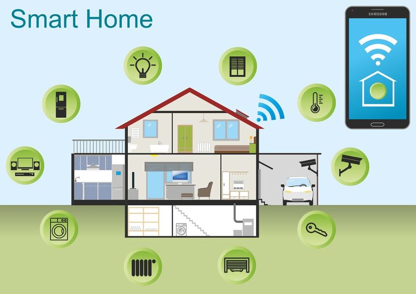
Figure 2: A typical legacy utility energy delivery process
Figure 2 [2] presents a structural view of a traditional electric power system where power flows from the
generator to the customer. While electricity supply changes from large, centralized generators to a mix
16with a greater percentage of distributed generation, the core delivery mechanism consisting of
transmission, sub-transmission, distribution, and customers remain the same.
• Transmission. Transmission covers the transportation of bulk quantities of electric energy via
electric conductors, from generation sources to an electric distribution system, load center, or tie-
line with a neighboring utility. Transmission involves the high-voltage flow of electricity from
the points of generation to locations of groups of electricity users, industrial parks, and
commercial centers. Transmission is almost always designed to be a grid – multiple paths to get
power to a single location.
• Sub-transmission. Sub-transmission is part of an electric power transmission system that runs at
relatively lower voltages. It is uneconomical to connect all distribution substations to
transmission voltages because the equipment required is larger and more expensive. Typically,
only larger substations connect with this high voltage. It is stepped down and sent to smaller
substations in communities and neighborhoods. Sub-transmission circuits are usually arranged in
loops or networks, preventing a single line failure that cuts off service to many customers for
more than a short time.
• Distribution. A distribution system carries electricity coming through the transmission or sub-
transmission grid and delivers it to consumers. Typically, the network would include medium-
voltage, less than 50 kV power lines, substations, and pole-mounted transformers, low-voltage,
less than 0.5 kV, distribution wiring, and meters. An electric distribution system delivers electric
energy to consumers. Distribution systems are primarily radial. Increasingly distribution systems
are designed as redundant radial or looped radial where customers could be fed from two possible
paths. Downtown distribution systems in some cities are also networked (meshed). As more
generation in the future is connected at the distribution level, utilities may consider designing
more portions of the distribution network to be more truly networked, similar to transmission
system design.
• Customer. Customers are the consumers of electricity. They are grouped into specific categories
depending on their quantity of use or where they are connected to the electric utility grid. Typical
categories are residential, commercial, agricultural, industrial, and transportation.
1.2. Utility transformation
For the past two decades, the electric grid has undergone a significant transformation, and this
transformation is expected to accelerate. The major changes are due in large part to:
• Changing themes on regulatory mandates and legislative policy
Electric utilities are wrestling with the push and the pull of more renewables coming online
through changing regulatory policy with the overarching need to deliver reliable power to their
customers at an affordable cost.
• Increased options for solving the same problem
Distributed Energy Resources (DER) and Non-Wires Alternatives (NWA3) provide new options
for generation, transmission, distribution, and consumption of power. Examples include:
3
Non-wires alternatives (NWAs) are electric utility system investments and operating practices that can
defer or replace the need for specific transmission and/or distribution projects, at lower total resource
cost, by reliably reducing transmission congestion or distribution system constraints at times of maximum
demand in specific grid areas. Examples include demand response, distributed generation (DG), energy
efficiency, electricity and thermal storage, load management, and rate design. The most common usage of
NWA is energy storage.
17o Energy storage vs. demand response where either of these can can help achieve load
reduction.
o Energy storage vs. peak-supply generators where a storage device charging during low
demand can supply power to fulfill on-peak demand
o Energy storage vs. grid expansion where a storage device can delay or eliminate the need
for an expansion of a feeder or substation’s capabilities
o Distributed wind/solar farms and other NWAs that can provide localized sources of real
and reactive power when needed.
The number, size, and impact of DERs and NWAs in the grid are increasing. Their presence
is greater in some markets and less in others, but there is an unmistakable global trend in that
their number and size are growing. While not all of them are renewable, it is important to
note that the most significant growth area is renewable DERs. These resources bring
challenges of intermittency, variability of output, and location that impact the reliable and
resilient operation of the grid. As energy storage technology costs drop, growth in this form
of DER will increase dramatically.
• Increased focus on security
There is now a well-documented and increasing cyber threat from malicious actors seeking to
disrupt the electricity system that everyone relies on to power homes and businesses [3]. The
safety and security of a nation’s critical infrastructure depend on its resilience to incidents such as
cyber-attacks.
• More affordable and up-to-date Operations Technologies (OT)
Sensors and controls exploiting cheaper access to ubiquitous communications allow the utility
operator to control the flow of power at lower costs. These technologies also allow ease of
deployment and integration of additional sensors (e.g., Automated Meter Reading [AMI] data)
and access to data from existing third-party sensors (e.g., solar irradiance data) into the
operational environment. A potential game-changer that is being considered by many utilities for
grid operations (reliability and market) is wireless communication, notably private LTE.
• Computer Science and Information Technology (IT) advances
Cloud computing, mobile computing, machine learning, big data analytics, and artificial
intelligence can enable companies to implement advanced solutions more efficiently and at a
lower cost allowing smaller utilities access to capabilities that they would never have been able to
deploy. Additionally, newer architecture concepts allow the building of loosely coupled and more
distributed systems that allow components to be added/removed in a plug-and-play manner
without disrupting the entire system. Noteworthy among these is the movement of computing and
artificial intelligence at the edge.
• Growing customer expectations
The mobile-internet-device enabled electric utility customer now expects their utility to provide
quick feedback on the status of outages, more choice on power use, and the ability to interact via
apps. Customers also expect electricity service that can adapt to changing societal priorities and
expectations.
• Customer grid interactions beyond energy consumption
Customers are also introducing other changes. They are installing wind turbines and rooftop
solar, buying electric cars that can also be used for energy storage. At the residential level, this is
seen in the BYOD (Bring Your Own Device) model, where customers bring devices such as
storage, electric vehicles, rooftop solar, and others connecting them behind the meter (BTM). In
18the more than 100-year history of the utility industry, this is the first transformation heavily
influenced by customers. Most of the previous transformations, such as wholesale and retail
deregulation, have always been driven by legislation and regulation. Legislation and regulation
are predictable. Customer behavior is unpredictable. These changes impact the transmission and
distribution levels, changing the delivery landscape and the traditional utility/customer
relationship.
• Business Model Changes
Experiences from retail markets in ERCOT and several states with retail choice (e.g.,
Pennsylvania, Illinois, California, Massachusetts) have led to new business entities like
aggregators. In addition to providing retail energy services, these entities may also provide other
value-added services to the customer, thereby creating the possibility of relegating the traditional
utility to merely a wires-and-pipes entity. They are also forcing the utility to change their
offerings to customers, such as the shift to a subscription model (fixed bill + clean energy +
thermostat), Time-of-Use (TOU) rates, sub-metered TOU for EVs, and others. A similar situation
arises with the emergence of community choice aggregators in states such as California and New
York [4].
While much, if not most, of these changes happen at the sub-transmission and distribution system level,
the aggregated effects (e.g., FERC Order 2222 – See Section 4.2) are significant enough to impact the
transmission systems of the future. These changes and others can significantly alter the future structure
and role of the traditional transmission system requiring the need for integrated grid (transmission and
distribution) planning and operations.
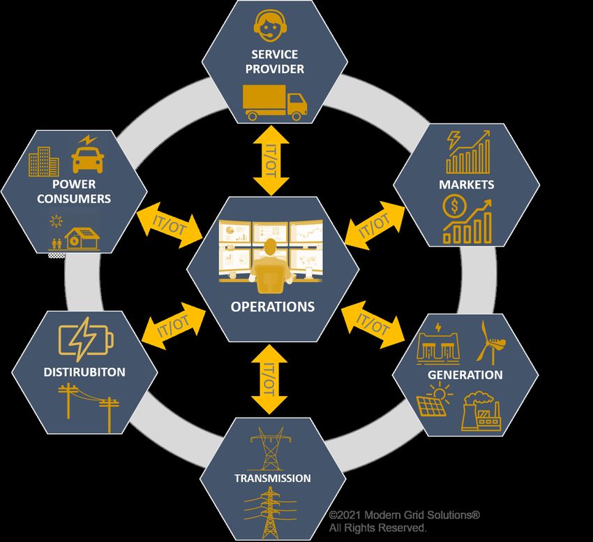
192. Participants and their impact on system operations
The industry is changing – new stakeholders are performing functions previously provided by established
utility industry incumbents. Figure 3 presents a conceptual view of the various stakeholders and how they
are connected to each other across the energy value chain.
This section is mainly focusing on the stakeholders who are new, emerging, or transforming. As this
narrative gets into the following subsections, two key terms need to be defined.
• System Operators (SO) is the general term for the entity responsible for managing the
transmission and distribution grids, and in vertically integrated utilities, for also dispatching the
generation. On the business side, SO performs contract management and reconciles physical
energy consumption supporting financial settlements. Further, SO also coordinates energy
schedules and manages network congestion. [5]
• Distribution System Operator (DSO) is a new and still-evolving term that, at its core, performs
today’s function of managing and operating the distribution system. However, as it evolves, some
future projections of this function could include operations planning and distribution/retail market
operations (somewhat like the RTO/ISO but at the distribution/retail level).
2.1. Vertically integrated utility
While the traditional utility will still endure for some time, it is unknown what form of transformation
will take in each jurisdiction. It is generally accepted that in each jurisdiction in the U.S. and worldwide,
some level of disaggregation and even consolidation will occur. Some changes are happening due to
regulatory mandates, while others result from economics and the need to stay competitive in this time of
rapid change. For example,
• Consolidation: There is significant merger and acquisition activity taking place in the Investor-
Owned Utility (IOU) space leading to the formation of holding companies such as Exelon
Utilities, Duke Energy, Berkshire Hathaway Energy, and others having several utilities within
their portfolio. [6,7]
• Disaggregation: Some utilities are seeing a push toward municipalization. Examples of these are
Boulder’s failed attempt at seceding from Xcel Energy and more recent attempts to break up
PG&E in California.
• Erosion of the value chain: With the growth of DERs, vertically integrated utilities see a
combination of coal-fired and nuclear plant retirements, new natural-gas plants coming online,
and tremendous growth in energy supply from renewables, wind, or solar, based on location.
Many solar-powered and wind-powered locations are also supported by localized storage
installations providing a greater degree of dispatchability. Given their regional and locational
diversity, these installations can provide increased flexibility for system operators to dispatch
energy and ancillary services. The journey to maturation of storage technology will drive the
industry towards the full transition to renewable for two reasons: dispatchability and localized
stability.
These changes affect the traditional utility through erosion of monopoly protection from competition,
resulting in the need to make the utility a beneficiary versus victim of electrification and justify/extend the
value of providing grid services differently.
20Figure 3: Impact of changes along the energy value chain
REBA – Renewable Energy Buyers Alliance
21System Operations Impacts: Operations at traditional utilities will be impacted by distributed energy
resources, large, centralized renewables, and microgrids, all of which could be either utility, customer-
owned or third-party owned. All the stakeholders identified in this section could also exist within a
utility's jurisdiction. Utility system operational functions must support their own needs and those of the
various stakeholders. One of the biggest challenges that system operators face in the near and mid-term
future will be to dispatch these newer and more intermittent sources of generation to provide continued
reliability and resiliency to the network. In some cases, system operations will not have control or
dispatch authority of DERs and will need to manage the grid in a manner that flexes with the economic
signals these sources will respond to.
2.2. Regional Transmission Organizations, Independent System Operator
(RTO/ISO)
An RTO in the United States is an electric power transmission system operator that coordinates, controls,
and monitors an electric grid across multiple states. An independent system operator (ISO) is similarly an
organization that also coordinates, controls, and monitors the electric grid, but usually within a single
U.S. state, although can cover multiple states. RTOs typically cover a larger geographic area. The creation
of RTOs was initiated by FERC Order No. 2000, issued on December 20, 1999 [8]. The potential for
significant impact to the RTO comes from the more recent FERC Order 2222 [9]. This rule enables DERs
to participate alongside traditional resources in the regional organized wholesale markets through
aggregations; opening U.S. organized wholesale markets to new energy and grid services sources. This
rule allows several sources of distributed electricity to aggregate to satisfy minimum size and
performance requirements that each may not meet individually.
System Operations Impact: RTOs have been in existence for several years, and their interactions with
most participants are quite mature. However, the impact of the recently introduced FERC order 2222 is
not yet fully known. This is mainly because most of these resources are connected to the distribution
system traditionally under the DSO’s control, whose role in the electric value chain is still evolving. In
addition, it is unknown how distribution-level resources will provide services in the wholesale market.
2.3. Community Choice Aggregation (CCA)
CCAs, also known as municipal aggregation, are programs that allow local governments to procure power
on behalf of their communities (residents, businesses, and municipal accounts) from alternative suppliers
while still receiving transmission and distribution services from their existing utility provider. CCAs are
an attractive option for communities that want more local control over their electricity sources, for
example, more green power options than those offered by the local distribution utility, lower electricity
prices, and a source of additional community revenue. By aggregating demand, communities gain
leverage to negotiate better rates with competitive suppliers and choose greener power sources [10]. In
2021, CCAs delivered about 52 GWHs of green power to about 4.3 million customers [11] across 190+
cities and counties (e.g., Napa, Sonoma, and Marin) in California alone [12]. Also, several other states are
exploring CCAs.
System Operations Impact: The main impact of CCAs is in separating power procurement from power
delivery at the distribution level. This separation creates a potential for lack of transparency to the system
operator of the CCA actions, resulting in operational challenges due to the decoupling of system control
and responsibility for operations. This impact is like that of the wholesale market, where the generation
procurement is external to the System Operator. Wholesale markets have multiple generation suppliers,
whereas, in this case, the CCA is the only supplier. This concept is still new, and its long-term success
and viability still need to be observed. Few, if any, CCAs thus far have faced a complete life cycle of
resource procurement with contingencies.
22The location of the sources where CCAs are procuring power adds an extra layer of complexity. In some
cases, CCAs either build or procure significant long-term power contracts from large solar farms and
individual residential customers with DER. However, suppose a significant percentage of the power
procured is from individual residential customers who send their surplus power back into the grid. In that
case, the system operator requires increased visibility into the amount and location of energy injected into
the distribution grid. In addition, key functions such as load/resource forecasting (including DERs),
scheduling/dispatch, and others need to be quite sophisticated to manage power flows from these sources.
2.4. Aggregators
Aggregators are a relatively recent business entity in the utility landscape. Some aggregators appeared
following the creation of the ERCOT marketplace [13] in 1996, and many more came into existence over
the last few years. Aggregators in the market structure provide value by capturing customer groups and
providing services a utility fails to or is not allowed to perform. These are private enterprises that could be
entirely independent of the incumbent utility or unregulated utility subsidiary. They could also be the
utility acting as an aggregator under some specific circumstances [14]. Examples of aggregator services
provided are listed below.
• Procure energy from wholesale suppliers and provide it to their customers. The energy source
could be from traditional energy sources, such as fossil or hydro. Others are also providing
renewable energy by contracting with entities such as solar and wind farms.
• Procure energy from a large group of suppliers and supply them to the wholesale markets. This
energy could be from a broad range of sources: traditional, renewable, residential, commercial,
or others. The energy source could also be Demand Response (DR) services or a virtual power
plant operator. These are the disruptors in the marketplace who can take services offered to a
large and diverse group of customers and trade them in the broader wholesale market. The
reduction in load from DR is offered either as a generation or ancillary service.
The aggregator may also pay someone to procure (e.g., DR) services in a service territory. In
this case, the DR aggregator is, in effect, a technology vendor that provides integrations saving
time for utility software development. Additional add-ons may be marketing, customer care, and
event scheduling.
• Bundling energy, home security, telecom, and other such services by providing a single billing
and customer service mechanism. For example, the Retail Electric Providers (REP) in the
ERCOT marketplace are quite successful with these offerings [15].
The implementation of FERC Order 2222 [16] brings greater complexity by ordering wholesale markets
to engage aggregators. Under FERC 2222, aggregators have access to customers from around 125
utilities. That number would be higher if it were not for the four million megawatt-hour minimum in
annual volume rule prohibiting system operators from accepting aggregator bids for smaller utility
customers. This order may force larger utilities into an aggregator role to remain competitive. The initial
impact will be on those utilities under RTO/ISOs, but non-RTO/ISO members may eventually be subject
to FERC 2222 if they are FERC-regulated.
System Operations Impact: The aggregator can have some of the most complex impacts on the System
Operator. The aggregator's services are not precisely defined or limited to a concise set of services.
However, at a minimum, an aggregator (1) has an agreement to procure power for their customers, (2)
possibly modify their customers' consumption (DR), and (3) may deliver power procured from multiple
sources to and represent load in a wholesale market.
It remains the utility's responsibility to ensure customers get power reliably. To work effectively, there
needs to be close interaction between the transmission (wholesale) operator, DSO, and the aggregator to
ensure that the aggregator's actions are fully visible to both sets of operators and included in both real-
time operations and forecasts.
232.5. Renewable Energy Buyers Alliance (REBA)
Energy buyers are combining forces to procure renewable energy. REBA [17] is one such membership
association for large-scale energy buyers seeking to procure renewable energy across the U.S. It includes
stakeholders from across the commercial and industrial sector, non-profit organizations, as well as energy
providers and service providers. Its objective is to create a single marketplace for all nonresidential
energy buyers to transition to a cleaner, zero-carbon energy future.
Since 2014, the REBA community has grown to over 200 large energy buyers and over 150 clean energy
developers and service providers. Participants in the REBA community have been a part of 95 percent of
all large-scale U.S. corporate renewable energy deals thus far.
REBA aims to catalyze 60 gigawatts (GW) of new renewable energy by 2025 and expand the number of
organizations buying clean power from dozens today to tens of thousands.
System Operations Impact: In essence, REBA is a type of aggregator where the generation procurement
is external to the system operations function. However, just like CCAs, there is additional complexity.
Since, as the name implies, much of this procured power is based on renewables, the transmission
operator and DSO will need to have full visibility into the amount and location of energy coming into the
grid. As a result, load forecasting will need to be quite sophisticated and possibly down to the feeder level
and perhaps to even lower levels of the grid.
2.6. Microgrid operator
According to the U.S. DOE Microgrid Exchange Group (MEG) [18], a microgrid is a group of
interconnected loads and distributed energy resources within clearly defined electrical boundaries that act
as a single controllable entity for the grid. A microgrid can connect and disconnect from the grid to
operate in either grid-connected or island mode.
System Operations Impact: Microgrids bring several levels of challenges and opportunities to the
grid's operation.
1. Operation of the microgrid. At the Point of Common Coupling (PCC), the microgrid may
appear either as a load or a source. The System Operator focuses on managing load and electrical
supply to the area surrounding the microgrid, while the microgrid could be consuming, suppling,
or islanded. The microgrid's flexibility of actions complicates the system operator's ability to
balance load and supply. Depending on who controls the microgrid, the complexity increases
because microgrids often contain one or more DERs, impacting real-time dispatch and
management of the electricity supply.
2. Operation of the distribution grid connected to multiple microgrids. These can be utility-
owned and or third-party owned. The DSO's actions must provide a reliable electricity supply
and be viewed as commercially fair to the third-party microgrid owners.
3. Load forecast. The system operator will need to forecast its load (power delivery) obligations to
consider whether the microgrid is functioning in a grid-connected or grid-disconnected mode.
2.7. Customers installing renewables and non-wired alternative solutions on
the grid
Large numbers of individual customers (residential, commercial, and industrial) install DERs and connect
them to the grid across the country. Examples of installations include photovoltaic (PV), storage, and PV
plus storage.
System Operations Impact: Depending on the installation's size and interconnection location, the DER
or NWA will need to be visible and controllable by the System Operator. If visible or controllable, then
information on the installation will also need to be provided to the System Operator so that the installation
24You can also read