DESIGN IMPROVEMENT OF A GAS-FIRED PYROLYSIS REACTOR - DOI
←
→
Page content transcription
If your browser does not render page correctly, please read the page content below
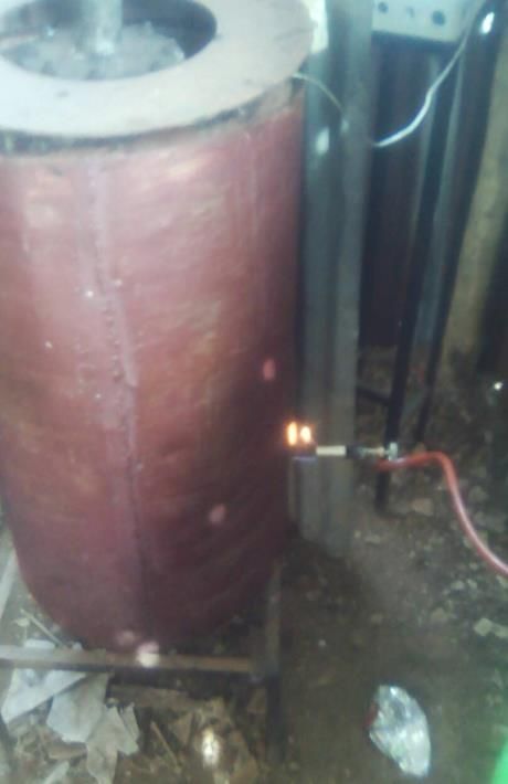
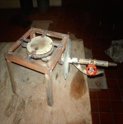
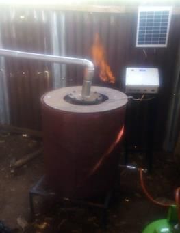
Engineering & Technology Research Journal (Print) ISSN 0794-2834
 Volume 6(1) pp. 22-29 (January-March 2021) (Online) ISSN 2736-1969

 DESIGN IMPROVEMENT OF A GAS-FIRED
 PYROLYSIS REACTOR
 1, *
 AKINBOMI, J.G., 1OYEDEKO K.F.K., 1SALAMI, L., 1AMINU, K.A.,
 2
 ANOZIE, A.N., 3SONIBARE, J.A.
 1
 Department of Chemical Engineering, Lagos State University, Lagos, Nigeria
 5
 Department of Chemical Engineering, Covenant University, Otta, Nigeria
 6
 Department of Chemical Engineering, Obafemi Awolowo University, Ile-Ife, Nigeria
 *julius.akinbomi@lasu.edu.ng; kfkoyedeko@yahoo.com; salamilukumon@yahoo.com
 ameenlasu@gmail.com; ambrose.anozie@covenantuniversity.edu.ng; asonibare@oauife.edu.ng

Received: 4th September 2020
Accepted: 14th January 2021
Published: 24th March 2021
https://doi.org/10.47545/etrj.2021.6.1.073

ABSTRACT
Design defects in a reactor often results in poor reactor performance. This study examined the effects of variations
in burner holes and air to fuel ratio on thermal efficiency and emission characteristics of three locally fabricated
gas cooking stoves with 48, 96 and 144 burner holes. The purpose of the study was to use the stove design with
optimal efficiency and lowest emissions, as a model for improving the design of a gas-fired pyrolysis reactor that
had air-fuel intake port defect with consequent incomplete combustion. The results of the study showed that stove
with 96 burner holes produced the lowest emissions of 89.672 mg/m3 while stove with 144 burner holes was found
to be the most fuel efficient with efficiency of 69.0. The results imply that a trade-off exists in the design of the
burners to achieve either the most environmentally-friendly or most fuel-efficient burner. However, a compromise
of the two objectives of maximizing fuel efficiency and minimizing emissions was reached by choosing as a
model, the burner having 96 holes with thermal efficiency of 64.3% and emissions of 89.672 mg/m3 over burner
having 144 holes with thermal efficiency of 69.0% and emissions of 258.974 mg/m3.

Keywords: Air flow, , Burner Holes, Combustion, Emissions, Improved design, Thermal efficiency

1. INTRODUCTION

Combustion process in defective combustion appliances often results in energy loss and environmental pollution.
In fact, a significant source of air pollution is the emission from incomplete combustion process [1-3]. Defective
combustion appliances can produce combustion pollutants including carbon monoxide (CO), oxides of nitrogen
(NOx), sulphur dioxide (SO2) and total suspended particulates (TSP); that can have adverse effects on human
health [4-6]. The usage of non-defective combustion appliances and understanding the way certain fuels burn in
combustion appliances will definitely help to overcome the problems of incomplete combustion of fuels.
Meanwhile, liquefied petroleum gas (LPG) is one of the common fuels used for combustion in both domestic and
commercial applications, and it has been proven to be a safe fuel for cooking and other applications. However,
using inefficient stoves or combustion appliances to burn LPG can actually make it to be unsafe. Therefore, there
is a need to explore ways to further improve thermal efficiency of LPG combustion appliances including cooking
stoves. A large number of improved cooking stove models have been developed [7-13] and studies are still
ongoing to find ways to burn fuels more efficiently.

The motivation for this study was the desire to find a solution to the problem of incomplete combustion that
occurred during a research study on a project titled ‘Asphalt making potential of pyrolytic bitumen from waste
rubber tyre: an adaptive measure to climate change’ [14]. The most obvious limitation of the study was the
technical hitch of inefficient design of the air-fuel intake port of the pyrolysis furnace. The air-fuel intake port
regulated the ratio of air to fuel that would produce desired burning flame in the gas-fired furnace (Plate 1a and
1b). The furnace of the pyrolysis reactor system had an air inlet to mix the fuel gas with air for complete
combustion as the case in most LPG stoves. However, the intake port of the pilot scale pyrolysis reactor could not
promote good air/fuel mixing for complete combustion as indicated by the yellow flame produced in the furnace
throughout the period of the investigation. This might be responsible for the loss of valuable time and heat energy
experienced during the experimental stage. It clearly showed that the reactor design was not efficient and needed
Akinbomi et al, 2021 22 www.etrj.com.ng
© 2021 Faculty of Engineering, Lagos State University, Ojo. Nigeria. All rights reserved.
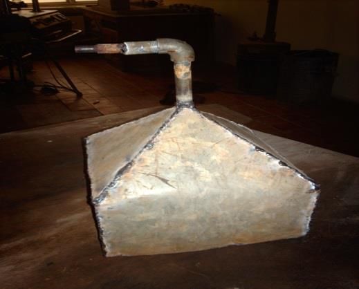
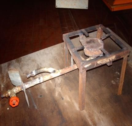
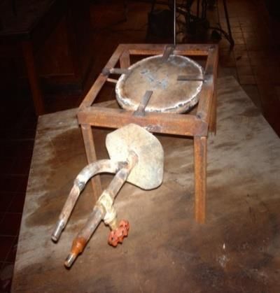
Engineering & Technology Research Journal (Print) ISSN 0794-2834
 Volume 6(1) pp. 22-29 (January-March 2021) (Online) ISSN 2736-1969
to be improved upon in future related research to avoid loss of valuable fuel energy and environmental pollution.
The limitation necessitated brainstorming on possible measures to overcome the challenge. One of the measures
which focused on the laboratory study of thermal efficiencies and air pollution impacts of liquefied petroleum gas
burners formed the basis of this study.

 (a) (b)

 Plate 1: Gas-fired furnace with attached solar-powered temperature sensor [14]

Therefore, the present study aimed at evaluating the effects of design variable (number of burner holes) and
operating variables (fuel flow rate and air to fuel ratio) on the thermal efficiency and emission characteristics of
locally fabricated LPG cooking stoves in order to determine the stove design with optimal efficiency and lowest
emissions. This would give an insight on how to improve the design of the defective pyrolysis reactor system.

2. MATERIALS AND METHODS

2.1. Materials
Three cooking stoves were designed and fabricated using galvanized iron sheet (Plate 2 a-c). The cooking stoves
were designed to burn LPG using regulated amount of air for combustion to produce luminous blue flame. The
number of burner holes on stoves 1, 2 and 3 were 48, 96 and 144, respectively, with each burner hole having 2
mm diameter. The burner of each of the three stoves was made by cutting, folding and welding 10cm wide
rectangular plate to form circular ring. To the end of the circular ring, flat circular plate with the burner holes was
welded. A non-perforated flat circular plate of the same dimensions as that at the top was welded to the bottom
end of the ring. A hole was drilled at the centre of the bottom plate and ¼ inch galvanized pipe for fuel flow was
welded to it. An elbow joint was used to change the direction of the pipe. Along the galvanized pipe, two openings
were made for the attachments of a ¼ gate valve and another pipe for the supply of a stream of air from a
compressor. Fuel flowed into the burner and was burnt with air supply from the compressor. The three stoves
were equipped with valves for air to fuel ratio adjustment. The whole burner unit was fitted to a rectangular frame
with a metal frame support for cooking pot and the stove was connected to the gas cylinder with rubber tubing. A
pressure regulator connected to the gas cylinder valve was used to supply the gas at constant pressure to the stove.
Regarding Hood exhaust duct, it was designed to collect a fairly high proportion of the emission gases while not
interfering in any way with the normal combustion of the stove. The hood consists of a skirt portion, four ducts
and an exit pipe (Plate 2d).

Akinbomi et al, 2021 23 www.etrj.com.ng
© 2021 Faculty of Engineering, Lagos State University, Ojo. Nigeria. All rights reserved.
Engineering & Technology Research Journal (Print) ISSN 0794-2834
 Volume 6(1) pp. 22-29 (January-March 2021) (Online) ISSN 2736-1969
2.2. Experimental Procedure
The experimental procedure involved measurement of thermal efficiencies and emission levels of SO 2, CO, NOx
and TSP from the fabricated gas cooking stoves. Thermal efficiency of each stove was determined by carrying
out water boiling test while gaseous and TSP emissions were determined by using portable gas monitors and
gravimetric method, respectively. The model numbers for NOx, CO and SO2 gas monitors used were RAE PGM-
1150, RAE PGM -1110 and RAE PGM -1130, respectively.

 (a) 48 burner holes (Stove 1) (b) 96 burner holes (Stove 2) (c) 144 burner holes (Stove 3)

 (d) Hood Exhaust Duct

 Plate 2: Fabricated experimental materials

Water Boiling Test was conducted to investigate the energy consumption efficiencies of the cooking stoves.
Empty aluminium cooking pot without its lid was weighed, and the weight was recorded. The pot was then filled
with known quantity of water (2kg). The weight of the pot and water were recorded. The pot with its contents was
then placed on the stove and initial temperature of the water in it was measured by using a clamp to place a
thermometer in the pot so that water temperature might be measured at the centre (5 cm from the bottom). The
flow rates of the air and the LPG (fuel), were then measured and the starting time was recorded as soon as the
stove started to burn with a bright flame. The temperature of the water was measured every five minutes until it
boiled (it reached the pre-determined local boiling point). The boiling temperature recorded over a five-minute
period at full boil and the maximum and minimum temperatures observed during this period were noted. The
maximum and minimum temperatures were then averaged and the result recorded as the “local boiling
temperature”.

The pot was then removed from the stove and the fire put off. The time taken to boil the water was measured and
recorded. The weight of the cool water that remained in the pot was also determined by weighing the pot and its
content again. The measured values of change in temperature of water, the time taken to boil the water, the quantity
of water evaporated and the volume of fuel consumed were used to calculate the energy consumption efficiency
of the stove using equation 1 [15]

Akinbomi et al, 2021 24 www.etrj.com.ng
© 2021 Faculty of Engineering, Lagos State University, Ojo. Nigeria. All rights reserved.
Engineering & Technology Research Journal (Print) ISSN 0794-2834
 Volume 6(1) pp. 22-29 (January-March 2021) (Online) ISSN 2736-1969
.
 ( − )+
 =
 × 100 1

where η is thermal efficiency (%); Mw is the initial mass of water in the cooking pot, kg; Cp is the specific heat
capacity of water at constant pressure, kJ/kg K; Tb is the boiling temperature of water, K; T o is the initial water
temperature, K; Me is the mass of water evaporated, kg; L is the latent heat of evaporation, kJ/kg; Vf is the volume
of fuel burnt (m3); and Ef is the calorific value of the fuel, J/kg.

The Water Boiling Tests were carried out five times for each of the burner using different values for the gas flow
rates of liquefied petroleum gas and commensurate values for air flow rates each time. For each experimental run,
the experiments were replicated in triplicates and the average values taken each time. The velocity of air-fuel
mixture (V) through the burner holes was calculated using equation 2.

 = . 2

where Q is volumetric flow rate of air-fuel mixture, m3/s; N is the number of burner holes on a stove and A is the
cross-sectional area of one burner hole, m2.

Regarding the gaseous emission measurements, the concentrations of the air pollutants in the flue gas stream from
each stove were determined immediately after the water boiling test was carried out. Each stove was placed under
a hood and the concentrations of NOx, CO and SO2 in the flue gas stream were determined using NOx, CO and
SO2 battery-powered gas monitors respectively. The TSP measurements were made by gravimetric air sampling
method using Negretti Air Sampler. A metered volume of air was sampled through pre-weighed Whatman
cellulose filter paper of size 2.5 cm diameter. The low volume sampler was used to suck the sampled air through
a narrow inlet tube into a small flask containing the collection medium. All the filter papers were inspected for
defects and all the defective filter papers were rejected. The filter papers were conditioned in a room of constant
humidity and temperature before and after usage for air sampling. The sampling time was set to 5 minutes and the
flow rate of suction of ambient air was set by a rotameter. After sampling, the filters were taken out and placed in
a petri dish for 24 hour-desiccation. The dried filter papers were weighed on the same electronic balance on which
it was weighed initially. The concentration of the total suspended particulate matter (TSP) was calculated using
equation 3 [16].
 ( ) −
 = ( 3 )
 = ×
 3

where Wf is final weight of the filter paper, µg; Wi is initial weight of the filter paper, µg; F is the air flow rate,
m3/s and t is the sampling period, s.

3. RESULTS AND DISCUSSIONS

The average values of the results obtained during the experiments are given in Table 1. As indicated in the table,
the effect of number of burner holes on thermal efficiency of the stoves were such that the energy consumption
efficiencies of stove 1, stove 2 and stove 3 increased significantly with increase in number of burner holes. The
velocity of air-fuel mixture through the burner holes was also affected by the number of burner holes. such that
increase in the number of burner holes reduced the velocity of the air-fuel mixture through the burner holes. The
increase in thermal efficiency with number of burner holes could be due partly to the decrease in velocity of air-
fuel mixture through the burner holes which resulted in longer residence time and time available for heat transfer
from the hot combustion gases to the cooking pot. High velocity of gases tends to carry away the heat released
during combustion. The increase in cross-sectional area of the burner also gave room for proper mixing of air and
fuel before ignition since oxygen molecules must strongly collide with fuel molecules for heat-releasing chemical
reactions in combustible mixtures to take place. The energy consumption efficiencies of the stoves, however, did
not significantly change with increasing gas flow rate. This implies that change in gas flow rate entering the stoves
did not have significant influence on the change in energy consumption efficiencies of the stoves. This might be
due to reduction in residence time and time available for heat transfer to take place as the gas flow rate increased.

Regarding the relationship between boiling time, gas flow rate; and number of burner holes; the boiling time of
each cooking stove decreased with increase in both gas flow rate and number of burner holes. The rate of heating
was constant for the three stoves when operated at the same flow rate. The constant value obtained for the three
Akinbomi et al, 2021 25 www.etrj.com.ng
© 2021 Faculty of Engineering, Lagos State University, Ojo. Nigeria. All rights reserved.
Engineering & Technology Research Journal (Print) ISSN 0794-2834
 Volume 6(1) pp. 22-29 (January-March 2021) (Online) ISSN 2736-1969
stoves when operated at the same flow rate implies that only change in gas flow rate entering the stoves affected
the rate of heating but change in number of burner holes on the stoves did not affect the rate of heating. As regards
emissions, changes in gas flow rate, air to fuel ratio and number of burner holes did affect the concentrations of
emissions from the cooking stoves significantly. Meanwhile, SO2 emissions were not detected by the SO2 gas
monitor throughout the experiment. This could indicate that the concentrations of SO2 emissions from the three
stoves were below the detectable limit of the SO2 gas monitor.

The results of the study showed that stove with 96 burner holes (stove 2) produced the lowest total emission of
89.672 mg/m3, with the emission concentrations of CO, NOx and TSP being 43.85, 20.37 and 25.46 mg/m 3,
respectively. At this condition, the thermal efficiency and air to fuel ratio for stove 2 were 64.3% and 10.53,
respectively. Meanwhile, stove with 144 burner holes (stove 3) had the highest thermal efficiency of 69.0 % at air
to fuel ratio of 12.0. At this condition, the total emission from stove 3 was 258.974 mg/m3, with the emission
concentrations of CO, NOx and TSP being 212.00, 18.83 and 28.14 mg/m3, respectively. It could be deduced
from the results that stove 3 was the most fuel-efficient stove at air to fuel ratio of 12.0 while stove 2 was the most
environmentally-friendly stove at air to fuel ratio of 10.53. However, the results imply that a trade-off exists in
the design of the gas cooking stoves in specifying the number of burner holes to achieve either the most
environmentally-friendly or most fuel-efficient stoves. Therefore, a compromise of the two objectives of
maximizing fuel efficiency and minimizing emissions was reached by choosing as a model, the stove having 96
burner holes with thermal efficiency of 64.3% and emissions of 89.672 mg/m 3 over stove having 144 burner holes
with thermal efficiency of 69.0% and emissions of 258.974 mg/m3.

4. CONCLUSION

In the research work, the effects of design and operating variables on thermal efficiency and emission
characteristics of liquefied petroleum gas cooking stoves were studied. This was with a view to generating data
that would assist in developing efficient and environmentally-friendly stoves that could serve as models for new
or corrective designs of combustion appliances. The results of this study showed that there were optimal values
of burner holes and air to fuel ratio to achieve lowest emissions of air pollutants and acceptable thermal efficiency
of LPG cooking stoves. The stove having 96 burner holes with thermal efficiency of 64.3% and emissions of
89.672 mg/m3 at air to fuel ratio of 10.53, was chosen as a model stove for corrective design of the defective
pyrolysis furnace in order to maximize fuel efficiency and minimize emissions from the system. A proper
understanding of the effects of design and operating parameters on performance of stove in terms of efficiency
and emission of pollutants is, therefore, essential for the effective design of combustion appliances.

ACKNOWLEDGEMENT
The authors appreciate the support given in various forms by people such as Saheed, Amope, Salami, Ogidan,
Bibian and Asifat, as well as the engineers, Sola and Hammed, who were responsible for the fabrication of the
equipment.

REFERENCES

[1] M. Ezzati, H. Saleh, D.M. Kamen, ‘The contributions of emissions and spatial microenvironments to exposure
to indoor air pollution from biomass combustion in Kenya’. Environmental Health Perspectives, Vol.108, No 9,
2000, 833-839.

[2] M. Ezzati, D.M, Kammen, ‘The health impacts of exposure to indoor air pollution from solid fuels in
developing countries: knowledge, gaps, data needs and policy options’. Environmental Health Perspectives,
Vol.110, No 11, 1058-1068.

[3] K.R. Smith, J.M. Samet, I. Romieu, N. Bruce, ‘Indoor air pollution in developing countries and acute lower
respiratory infection in children’. Thorax, Vol. 55, 2000, 518-532

[4] R. Albalak, N. Bruce. J.P. McCracken, K.R. Smith, T. De Gallardo, ‘ Indoor respirable particulate matter
concentrations from an open fire, improved cookstove and LPG/open fire combination in a rural Guatemalan
community’. Environ Sci Technol, Vol. 35, No 13, 2001, 1650-1665.

Akinbomi et al, 2021 26 www.etrj.com.ng
© 2021 Faculty of Engineering, Lagos State University, Ojo. Nigeria. All rights reserved.
Engineering & Technology Research Journal (Print) ISSN 0794-2834
 Volume 6(1) pp. 22-29 (January-March 2021) (Online) ISSN 2736-1969
 Table 1: Results from measurement of thermal efficiencies and emissions from the fabricated gas cooking stoves
 Independent variable (LPG flow rate (litres/min) 0.80 0.85 0.90 0.95 1.00
 S/N Dependent variable
 1 Velocity of gas-air mixture (m/s) Stove 1(n=48) 0.863 0.923 0.960 1.210 1.270
 Stove 2(n=96) 0.458 0.494 0.574 0.607 0.690
 Stove 3(n=144) 0.361 0.389 0.427 0.449 0.480
 2 Rate of heating (kJ/s) Stove 1(n=48) 1.25 1.33 1.41 1.49 1.57
 Stove 2(n=96) 1.25 1.33 1.41 1.49 1.57
 Stove 3(n=144) 1.25 1.33 1.41 1.49 1.57
 3 Volume of fuel (m3) Stove 1(n=48) 40,160 x 10-6 39, 780 x 10-6 39,330 x 10-6 38,665 x 10-6 38,000 x 10-6
 Stove 2(n=96) 30, 336 x 10-6 29, 750 x 10-6 28,980 x 10-6 28, 690 x 10-6 28, 000 x 10-6
 -6 -6
 Stove 3(n=144) 24,000 x 10 23, 588 x 10 23, 040 x 10-6 22, 468 x 10-6 22,000 x 10-6
 3 -6 -6
 4 Volume of gas-air mxture (m ) Stove 1(n=48) 391, 560 x 10 390, 640 x 10 377, 961 x 10-6 445, 808 x 10-6 437, 000 x 10-6
 -6 -6
 Stove 2(n=96) 314, 888 x 10 313, 268 x 10 335, 009 x 10-6 330, 796 x 10-6 350, 000 x 10-6
 -6 -6
 Stove 3(n=144) 294,000 x 10 292,721 x 10 296, 986 x 10-6 288, 483x 10-6 286,000 x 10-6
 3 -4 -4
 5 Volumetric flow rate (m /s) Stove 1(n=48) 1.30 x 10 1.39 x 10 1.44x 10⁻⁴ 1.83 x 10⁻⁴ 1.92 x 10⁻⁴
 -4 -4
 Stove 2(n=96) 1.38 x 10 1. 49 x 10 1.73 x 10⁻⁴ 1.83 x 10⁻⁴ 2.08 x 10⁻⁴
 Stove 3(n=144) 1.63 x 10⁻⁴ 1.76 x 10⁻⁴ 1.93 x 10⁻⁴ 2.03 x 10⁻⁴ 2.17 x 10⁻⁴
 6 Boiling time (min) Stove 1(n=48) 50.20 46.80 43.70 40.70 38.00
 Stove 2(n=96) 37.92 35.00 32.20 30.20 28.00
 Stove 3(n=144) 30.00 27.75 25.60 23.65\ 22.00
 7 Air flow rate (litres/min) Stove 1(n=48) 7.00 7.50 7.75 10.00 10.50
 Stove 2(n=96) 7.50 8.10 9.50 10.0 11.50
 Stove 3(n=144) 9.00 9.70 10.7 11.25 12.00
 8 Air to fuel ratio Stove 1(n=48) 8.75 8.82 8.61 10.53 10.50
 Stove 2(n=96) 9.38 9.53 10.56 10.53 11.50
 Stove 3(n=144) 11.25 11.41 11.89 11.84 12.00
 9 Thermal Efficiency (%) Stove 1(n=48) 56.9 57.1 57.5 57.9 58.0
 Stove 2(n=96) 63.9 64.0 64.1 64.3 64.6
 Stove 3(n=144) 68.1 68.3 68.4 68.6 69.0
n = number of burner holes

Akinbomi et al, 2021 27 www.etrj.com.ng
© 2021 Faculty of Engineering, Lagos State University, Ojo. Nigeria. All rights reserved.
Engineering & Technology Research Journal (Print) ISSN 0794-2834
 Volume 6(1) pp. 22-29 (January-March 2021) (Online) ISSN 2736-1969
Table 1 (Cont.) Results from measurement of thermal efficiencies and emissions from the fabricated gas cooking stoves

 Independent variable (LPG flow rate, litres/min) 0.80 0.85 0.90 0.95 1.00
 S/N Dependent variable
 10 Energy intensity (kJ/g of water) Stove 1(n=48) 1.89 1.87 1.85 1.82 1.79
 Stove 2(n=96) 1.43 1.40 1.36 1.35 1.32
 Stove 3(n=144) 1.13 1.11 1.08 1.06 1.03
 11 Energy consumed (kJ) Stove 1(n=48) 3,775 3,739 3,697 3,635 3,572
 Stove 2(n=96) 2,852 2,797 2,724 2,697 2,632
 Stove 3(n=144) 2,256 2,217 2,166 2,112 2,068
 12 Carbon monoxide (CO) emission Stove 1(n=48) 34.43 42.17 48.50 351.32 204.69
 (mg/m3) Stove 2(n=96) 145.20 44.47 39.60 43.85 46.41
 Stove 3(n=144) 135.82 161.14 269.45 271.03 212.00
 13 NOx emission (mg/m3) Stove 1(n=48) 19.09 23.60 15.83 25.68 20.52
 Stove 2(n=96) 16.34 19.77 20.41 20.37 17.57
 Stove 3(n=144) 19.71 24.47 31.96 18.83 18.83
 14 Total Suspended Particle (TSP) Stove 1(n=48) 69,091 50,000 34,286 85,714 55,385
 emission (μg/m3) Stove 2(n=96) 40,000 28,800 57,143 25, 455 41,739
 Stove 3(n=144) 40,000 25,000 47,293 53,333 28,144
n = number of burner holes

Akinbomi et al, 2021 28 www.etrj.com.ng
© 2021 Faculty of Engineering, Lagos State University, Ojo. Nigeria. All rights reserved.
Engineering & Technology Research Journal (Print) ISSN 0794-2834
 Volume 6(1) pp. 22-29 (January-March 2021) (Online) ISSN 2736-1969

[5] L.P. Naeher, B. P. Leaderer, K. R. Smith, ‘Particulate matter and carbon monoxide in highland Guatemala:
indoor and outdoor levels from traditional and improved wood stoves and gas stoves’. Indoor Air, Vol.10. No 3,
2000, 200-205.

[6] J. Zhang, K.R. Smith, ‘Hydrocarbon emissions and health risks from cookstoves in developing countries. J.
Expo Anal Epidemiol, Vol. 6, No 2, 1996, 147-161

[7] A.N. Anozie, A.R. Bakare, J.A. Sonibare, T.O. Oyebisi, ‘Evaluation of Cooking Energy Cost, Efficiency,
Impact on Air Pollution and Policy in Nigeria. Energy,’ Vol. 32, No 7, 2007, 1283-1290.

[8] K. Yung-Chang, L. Ta-Hui, ‘Emissions and Efficiency of a Domestic Gas Stove Burning Natural Gases with
Various Compositions..’ Energy Conversion and Management, Vol. 44, No 19, 2003, 3001- 3014.

[9] P.P. Gohil, S.A. Channiwala, ‘Experimental investigation of performance of Conventional LPG cooking
stove’. Fundamental J. Thermal Science and Engineering, Vol. 1, No 1, 2011, 25-34.

[10] V.K. Pantangi, A.S.S.R. Karuna-Kumar, S.C. Mishra, N. Sahoo, ‘Performance Analysis of Domestic LPG
Cooking Stoves with Porous Media.’ International Energy Journal, Vol. 8, No 2, (2007), 139-144.

[11] M.Y. Khan, A. Saxena, ‘Performance Of LPG Cooking Stove Using Different Design Of Burner Heads’.
International Journal of Engineering Research & Technology (IJERT), Vol. 2, No 7, 2013, 656-659.

[12] M. Shukur, U. S. P. Shet, ‘Experimental Investigations on the Efficacy Augmentation of a Domestic LPG
Gas Stove using an Add-on Wire Mesh. International Journal of Engineering and Advanced Technology (IJEAT),
Vol. 6, No 3 ISSN: 2249 – 8958, Volume-6 Issue-4, 2017, 266-268.

[13] E.M. Wafula, M.M. Kinyanjui, L. Nyabola, E.D. Tenambergen, ‘Effect of improved stoves on prevalence of
acute respiratory infection and conjunctivitis among children and women in a rural community in Kenya’. East
African Medical Journal, Vol. 77, No 1, 2000, 37-44.

[14] J.G. Akinbomi, S.O. Asifat, A. Ajao, O. Oladeji. Asphalt Making Potential of Pyrolytic Bitumen from Waste
Rubber Tyres: An Adaptive Measure to Climate Change. In: W. Leal-Filho, editor, Handbook of Climate Change
Resilience, Springer, Chan, 2019, p. 1-15.

[15] S.C. Bhattacharya, D.O. Albina, A. M. Khaing, ‘Effects of selected parameters on performance and emission
of biomass-fired cookstoves’. Biomass and Bioenergy Vol. 23, No 5. 2002, 387-395.

[16] World Health Organization, WHO Collaborating Centre on Air Pollution Control &
WHO Collaborating Centre on Clinical and Epidemiological Aspects of Air Pollution. (1976). Selected methods
of measuring air pollutants, World Health Organization. https://apps.who.int/iris/handle/10665/37047

Akinbomi et al, 2021 29 www.etrj.com.ng
© 2021 Faculty of Engineering, Lagos State University, Ojo. Nigeria. All rights reserved.
You can also read