Ask the Experts: NFPA 110 for Emergency Power Systems - PowerHour webinar series for consulting engineers
←
→
Page content transcription
If your browser does not render page correctly, please read the page content below
Ask the Experts:
NFPA 110 for
Emergency
Power Systems
PowerHour webinar series for consulting engineers
Experts you trust. Excellence you count on.

March 25, 2021 2:00pm Eastern Time / 11:00am Pacific Time
(1 PDH issued by Cummins Inc.)
Welcome!
Cummins PowerHour webinar series is designed to help our engineer partners to…
§ Keep up to date on products, technology, and codes and standards development
§ Interact with Cummins experts and gain access to ongoing technical support
§ Participate at your convenience, live or on-demand
§ Earn Professional Development Hours (PDH)

Technical tips:
§ Audio is available through teleconference or Zoom application.
§ Attendees are in “listen only” mode throughout the event.
§ Use the Zoom Q&A Panel to submit questions, comments, and
  feedback throughout the event. Time is allotted at the end of the
  PowerHour to address Q&A.
§ If the audio connection is lost, disconnected or experiences
  intermittent connectivity issues, please check your audio connection
  through the "Join Audio" or "Audio Connectivity" button at the bottom
  left of the Zoom application.
§ Report technical issues using the Zoom Q&A Panel.
                                                                                 2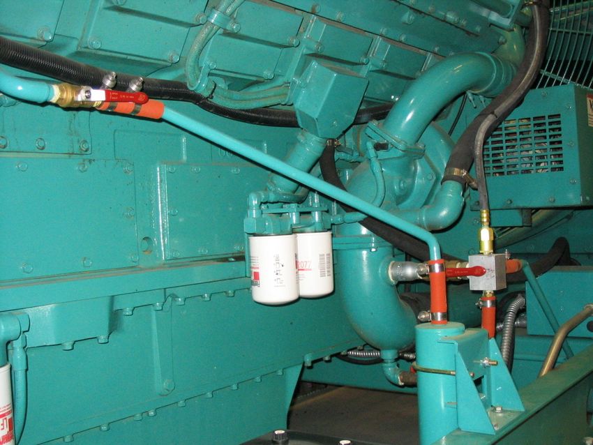
Course Objectives

Ask the Experts: NFPA 110 for Emergency Power Systems
NFPA 110, the Standard for Emergency and Standby Power Systems, sets the baseline for emergency
power system performance requirements and is critical to installation of nearly every backup power
system. This Ask the Experts session will address a number of key topics related to NFPA 110 and will
offer an opportunity to connect directly with power system experts at Cummins! Topics addressed during
this session will range from fuel and battery testing to Type 10 requirements and complexities arising from
paralleled power sources serving life safety loads. Bring your questions and be prepared to engage in
open discussion and Q&A with an expert panel.
After completing this course, participants will be able to:
•   Identify key topics related to NFPA 110 impacting emergency power supply system design and
    installation.
•   Describe common pitfalls, challenges and misconceptions often encountered when validating power
    system design.
•   Recognize common code requirements mandated by NFPA 110 and their practical application.

                                                                                                              3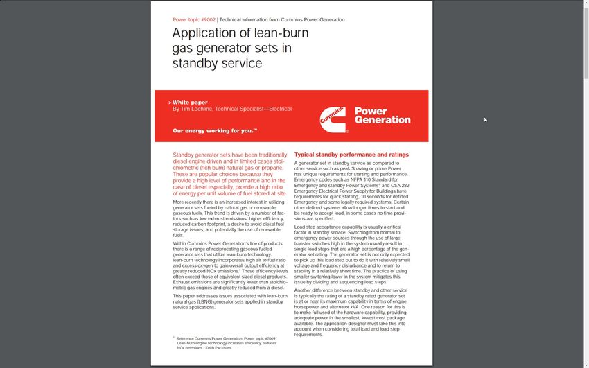
Asking a Question:

Q&A Button:
• For technical questions on today’s topic
• Ask at anytime
• Not all questions may get answered but we’ll do our best!

Chat Button:
•   For general PowerHour or Zoom questions

                                                              4
Disclaimer

The views and opinions expressed in this
course shall not be considered the official
position of any regulatory organization and
shall not be considered to be, nor be relied
upon as, a Formal Interpretation.
Participants are encouraged to refer to the
entire text of all referenced documents. In
addition, when it doubt, reach out to the
Authority Having Jurisdiction.

                                               5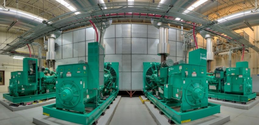
Meet your panelists
                                                                                                                                                Cummins
Cummins Panelists:                                                                                                                              Facilitator:

Michael Sanford                        Earnest Glaser                        Donald Sosa                             Trina Casbon               Mark Taylor
Product Strategy and Sales             Senior Sales Application              Senior Sales Application                Senior Sales Application   Technical Advisor
Enablement Leader                      Engineer                              Engineer                                Engineer                   Cummins Inc.
Cummins Inc.                           Cummins Inc.                          Cummins Inc.                            Cummins Inc.
       Your local Cummins contacts:
       Ø   AZ, ID, NM, NV: Carl Knapp (carl.knapp@cummins.com)                       Ø   TX: Scott Thomas (m.scott.thomas@cummins.com)
       Ø   CO, MT, ND, UT, WY: Christopher Scott (christopher.l.scott@cummins.com)   Ø   OK, AR: Wes Ruebman (wes.ruebman@cummins.com)
       Ø   CA, WA, OR, AK, HI: Brian Pumphrey (brian.pumphrey@cummins.com)           Ø   TN, GA: Mariano Rojas (mariano.rojas@cummins.com)
       Ø   MA, ME, NH, RI, VT: Jim Howard (james.howard@cummins.com)                 Ø   FL: Bob Kelly (robert.kelly@cummins.com)
       Ø   CT, MD, NJ, NY : Charles Attisani (charles.attisani@cummins.com)          Ø   NC, SC, VA: Bill Morris (william.morris@cummins.com)
       Ø   Northern IL, MI, IA : John Kilinskis (john.a.kilinskis@cummins.com)       Ø   Canada: Ian Lindquist (ian.lindquist@cummins.com)
       Ø   NE, SD, KS: Earnest Glaser (earnest.a.glaser@cummins.com)                 Ø   PA, MD: Brian Cathcart (brian.cathcart@cummins.com)
       Ø   IL, IN, KY, MO: Jeff Yates (jeffrey.yates@cummins.com)                    Ø   DE, MN, ND, OH, WI, WV: Michael Munson
       Ø   LA, MS, AL: Trina Casbon (trina.casbon@cummins.com)                           (michael.s.munson@cummins.com)                                             6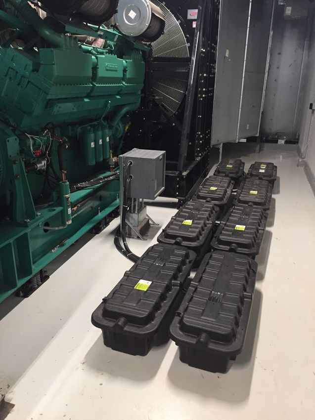
What are some examples of emergency
power system requirements that are
derived from NFPA 110?

                                      7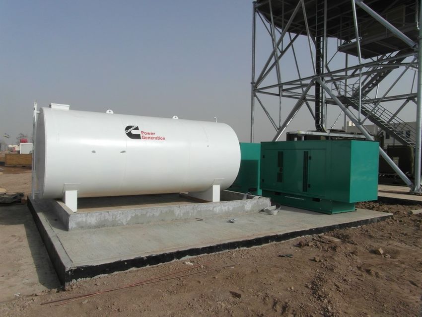
NFPA 110 Overview
Standard for Emergency and Standby Power Systems
Requirements covering the performance of emergency and standby power
systems providing an alternate source of electrical power to loads in buildings
and facilities in the event that the primary power source fails.

Covers installation, maintenance, operation, and testing requirements as they
pertain to the performance of the emergency power supply system (EPSS).

Intent of standard is to achieve maximum system reliability.

                                                                                  8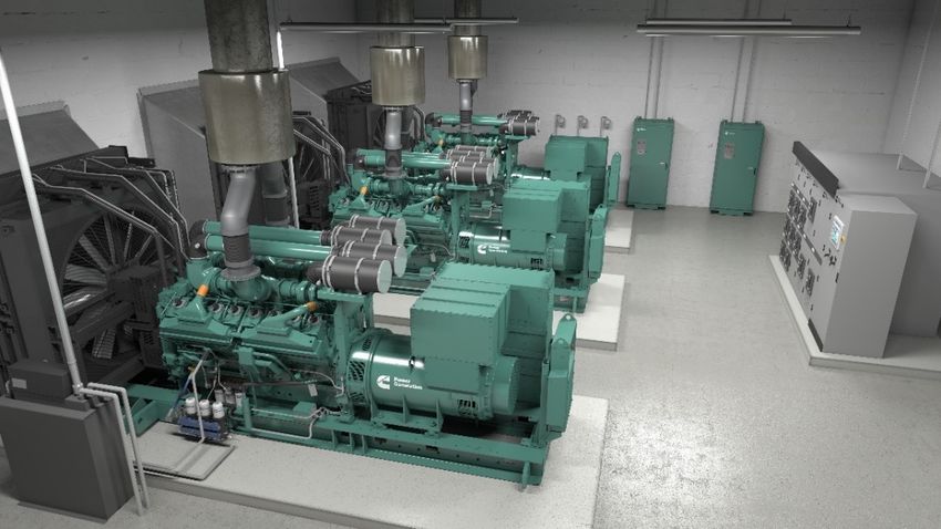
NFPA 110 Overview
Standard for Emergency and Standby Power Systems
Requirements covering the performance of emergency and standby power
systems providing an alternate source of electrical power to loads in buildings
and facilities in the event that the primary power source fails.

Covers installation, maintenance, operation, and testing requirements as they
pertain to the performance of the emergency power supply system (EPSS).

Intent of standard is to achieve maximum system reliability.

                                                                                  9
EPS
Emergency Power Source

                         10
EPSS
Emergency Power Supply System
11What is “Type” and how is it defined and
measured?
12NFPA 110 Overview
Classification of Emergency Power Supply Systems
4.2 Class. The class defines the minimum time, in hours, for which the EPSS is
designed to operate at its rated load without being refueled or
recharged.
4.3 Type. The type defines the maximum time, in seconds, that the EPSS will
permit the load terminals of the transfer switch to be without acceptable
electrical power.
4.4 Level. This standard recognizes two levels for equipment installation, performance
and maintenance requirements.
4.4.1 Level 1 systems shall be installed where failure of the equipment to perform
could result in loss of human life or serious injuries.
4.4.2 Level 2 systems shall be installed where failure of the EPSS to perform is less
critical to human life and safety.
Reprinted with permission from NFPA 110-2016, Standard for Emergency and Standby Power Systems, Copyright © 2015, National Fire Protection Association, Quincy, MA. This reprinted material is
not the complete and official position of the NFPA on the referenced subject, which is represented only by the standard in its entirety which can be obtained through the NFPA web site at www.nfpa.org. 13NFPA 110 Overview
Classification of Emergency Power Supply Systems
4.3 Type. The type defines the maximum time, in seconds, that the EPSS will
permit the load terminals of the transfer switch to be without acceptable
electrical power.
Reprinted with permission from NFPA 110-2016, Standard for Emergency and Standby Power Systems, Copyright © 2015, National Fire Protection Association, Quincy, MA. This reprinted material is
not the complete and official position of the NFPA on the referenced subject, which is represented only by the standard in its entirety which can be obtained through the NFPA web site at www.nfpa.org. 14NFPA 110 Overview
Classification of Emergency Power Supply Systems
4.3 Type. The type defines the maximum time, in seconds, that the EPSS will
permit the load terminals of the transfer switch to be without acceptable
electrical power.
Reprinted with permission from NFPA 110-2016, Standard for Emergency and Standby Power Systems, Copyright © 2015, National Fire Protection Association, Quincy, MA. This reprinted material is
not the complete and official position of the NFPA on the referenced subject, which is represented only by the standard in its entirety which can be obtained through the NFPA web site at www.nfpa.org. 15NFPA 110 Overview
Classification of Emergency Power Supply Systems
4.3 Type. The type defines the maximum time, in seconds, that the EPSS will
permit the load terminals of the transfer switch to be without acceptable
electrical power.
Related
Content NFPA 110 Time to Readiness
PowerHour
White Paper
Reprinted with permission from NFPA 110-2016, Standard for Emergency and Standby Power Systems, Copyright © 2015, National Fire Protection Association, Quincy, MA. This reprinted material is
not the complete and official position of the NFPA on the referenced subject, which is represented only by the standard in its entirety which can be obtained through the NFPA web site at www.nfpa.org. 16Why is there a time delay on start? What is
the purpose? Is it required?
17Utility Outage
Time Delay on Start
6.2.5 Time Delay on Starting of EPS. A time-
delay device shall be provided to delay starting of
the EPS. The timer shall prevent nuisance starting
of the EPS and possible subsequent load transfer
in event of harmless momentary power dips and
interruptions of the primary source.
A.6.2.5 For most applications, a nominal delay of
1 second is adequate. The time delay should be
short enough so that the generator can start and
be on line within the time specified for the type
classification.
Reprinted with permission from NFPA 110-2016, Standard for Emergency and Standby Power Systems, Copyright © 2015, National Fire Protection Association, Quincy, MA. This reprinted material is
not the complete and official position of the NFPA on the referenced subject, which is represented only by the standard in its entirety which can be obtained through the NFPA web site at www.nfpa.org. 18Utility Outage
Time Delay on Start
6.2.5 Time Delay on Starting of EPS. A time-
delay device shall be provided to delay starting of
the EPS. The timer shall prevent nuisance starting
of the EPS and possible subsequent load transfer
in event of harmless momentary power dips and
interruptions of the primary source.
A.6.2.5 For most applications, a nominal delay of
1 second is adequate. The time delay should be
short enough so that the generator can start and
be on line within the time specified for the type
classification.
Reprinted with permission from NFPA 110-2016, Standard for Emergency and Standby Power Systems, Copyright © 2015, National Fire Protection Association, Quincy, MA. This reprinted material is
not the complete and official position of the NFPA on the referenced subject, which is represented only by the standard in its entirety which can be obtained through the NFPA web site at www.nfpa.org. 19Utility Outage
Time Delay on Start
6.2.5 Time Delay on Starting of EPS. A time-
delay device shall be provided to delay starting of
the EPS. The timer shall prevent nuisance starting
of the EPS and possible subsequent load transfer
in event of harmless momentary power dips and
interruptions of the primary source.
A.6.2.5 For most applications, a nominal delay of
1 second is adequate. The time delay should be
short enough so that the generator can start and
be on line within the time specified for the type
classification.
Reprinted with permission from NFPA 110-2016, Standard for Emergency and Standby Power Systems, Copyright © 2015, National Fire Protection Association, Quincy, MA. This reprinted material is
not the complete and official position of the NFPA on the referenced subject, which is represented only by the standard in its entirety which can be obtained through the NFPA web site at www.nfpa.org. 20When we talk about or specify Class of
the EPS, how does that differ from
the recommended or requested onsite
fuel storage?
21NFPA 110 Overview
Classification of Emergency Power Supply Systems
4.2 Class. The class defines the minimum time, in hours, for
which the EPSS is designed to operate at its rated load without
being refueled or recharged.
4.3 Type. The type defines the maximum time, in seconds, that
the EPSS will permit the load terminals of the transfer switch to
be without acceptable electrical power.
4.4 Level. This standard recognizes two levels for equipment
installation, performance and maintenance requirements.
4.4.1 Level 1 systems shall be installed where failure of the
equipment to perform could result in loss of human life or
serious injuries.
4.4.2 Level 2 systems shall be installed where failure of the
EPSS to perform is less critical to human life and safety.
Reprinted with permission from NFPA 110-2016, Standard for Emergency and Standby Power Systems, Copyright © 2015, National Fire Protection Association, Quincy, MA. This reprinted material is
not the complete and official position of the NFPA on the referenced subject, which is represented only by the standard in its entirety which can be obtained through the NFPA web site at www.nfpa.org. 22NFPA 110 Overview
Classification of Emergency Power Supply Systems
4.2 Class. The class defines the minimum
time, in hours, for which the EPSS is designed
to operate at its rated load without being
refueled or recharged.
4.3 Type. The type defines the maximum time, in seconds, that
the EPSS will permit the load
terminals of the transfer switch to be without acceptable
electrical power.
4.4 Level. This standard recognizes two levels of equipment
installation ,performance and
maintenance.
4.4.1 Level 1 systems shall be installed where
failure of the equipment to perform could result in
loss of human life or serious injuries.
4.4.2 Level 2 systems shall be installed where
failure of the EPSS to perform is less
critical to human life and safety.
Reprinted with permission from NFPA 110-2016, Standard for Emergency and Standby Power Systems, Copyright © 2015, National Fire Protection Association, Quincy, MA. This reprinted material is
not the complete and official position of the NFPA on the referenced subject, which is represented only by the standard in its entirety which can be obtained through the NFPA web site at www.nfpa.org. 23Is regular testing of diesel fuel required and
if so, how frequently should it be
conducted?
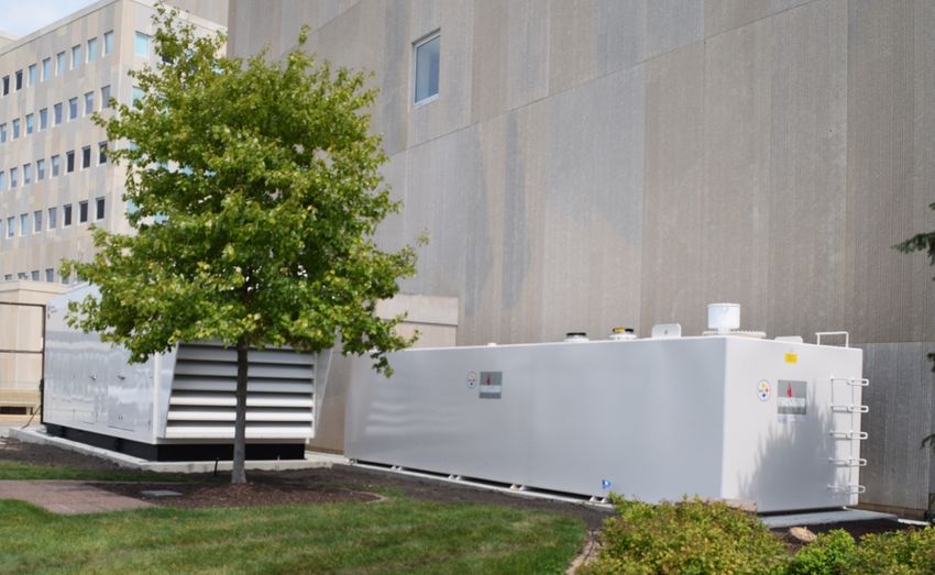
24NFPA 110 – Generator Set Subsystems
Engine Fuel System
7.9.1.2 Fuel system design shall provide for a
supply of clean fuel to the prime mover.
7.9.1.3 Tanks shall be sized so that the fuel is
consumed within the storage life, or provisions
shall be made to remediate fuel that is stale or
contaminated or to replace stale or contaminated
fuel with clean fuel.
8.3.7 A fuel quality test shall be performed at least
annually using appropriate ASTM standards or the
manufacturer’s recommendations.
Reprinted with permission from NFPA 110-2016, Standard for Emergency and Standby Power Systems, Copyright © 2015, National Fire Protection Association, Quincy, MA. This reprinted material is
not the complete and official position of the NFPA on the referenced subject, which is represented only by the standard in its entirety which can be obtained through the NFPA web site at www.nfpa.org. 25NFPA 110 – Generator Set Subsystems
Engine Fuel System
7.9.1.2 Fuel system design shall provide for a
supply of clean fuel to the prime mover.
7.9.1.3 Tanks shall be sized so that the fuel is
consumed within the storage life, or provisions
shall be made to remediate fuel that is stale or
contaminated or to replace stale or contaminated
fuel with clean fuel.
8.3.7 A fuel quality test shall be performed at least
annually using appropriate ASTM standards or the
manufacturer’s recommendations.
Reprinted with permission from NFPA 110-2016, Standard for Emergency and Standby Power Systems, Copyright © 2015, National Fire Protection Association, Quincy, MA. This reprinted material is
not the complete and official position of the NFPA on the referenced subject, which is represented only by the standard in its entirety which can be obtained through the NFPA web site at www.nfpa.org. 26NFPA 110 – Generator Set Subsystems
Engine Fuel System
7.9.1.2 Fuel system design shall provide for a
supply of clean fuel to the prime mover.
7.9.1.3 Tanks shall be sized so that the fuel is
consumed within the storage life, or provisions
shall be made to remediate fuel that is stale or
contaminated or to replace stale or contaminated
fuel with clean fuel.
8.3.7 A fuel quality test shall be performed at least
annually using appropriate ASTM standards or the
manufacturer’s recommendations.
Spec Note Require vendors to provide service and maintenance
contracts that include fuel testing at least annually.
Reprinted with permission from NFPA 110-2016, Standard for Emergency and Standby Power Systems, Copyright © 2015, National Fire Protection Association, Quincy, MA. This reprinted material is
not the complete and official position of the NFPA on the referenced subject, which is represented only by the standard in its entirety which can be obtained through the NFPA web site at www.nfpa.org. 27How and when should I be testing the
emergency power supply system?
28EPS Testing with Load
8.4.2 Generator sets in service shall be exercised at least once monthly, for a minimum of 30
minutes, using one of the following methods:
(1) Loading that maintains the minimum exhaust gas temperatures as recommended by the
manufacturer
(2) Under operating temperature conditions and at not less than 30 percent of the EPS
standby nameplate kW rating
8.4.2.3 Diesel-powered EPS installations that do not meet the requirements of 8.4.2 shall be
exercised monthly with the available EPSS load and shall be exercised annually with
supplemental loads at not less than 50 percent of the EPS nameplate kW rating for 30
continuous minutes and at not less than 75 percent of the EPS nameplate kW rating for 1
continuous hour for a total test duration of not less than 1.5 continuous hours.
Recommendation Test emergency generator sets at least monthly for at least
30 minutes with a load bank at no less than 30% of the generator set rating.
Reprinted with permission from NFPA 110-2016, Standard for Emergency and Standby Power Systems, Copyright © 2015, National Fire Protection Association, Quincy, MA. This reprinted material is
not the complete and official position of the NFPA on the referenced subject, which is represented only by the standard in its entirety which can be obtained through the NFPA web site at www.nfpa.org. 29Transfer Switch Operational Testing
8.4.6 Transfer switches shall be operated monthly.
8.4.6.1 The monthly test of a transfer switch shall consist of
electrically operating the transfer switch from the primary position
to the alternate position and then a return to the primary position.
Spec Note Employ transfer switch functionality that enables seamless
transition from normal to emergency source and back with minimal
interruption to loads (active sync in-phase transition).
Reprinted with permission from NFPA 110-2016, Standard for Emergency and Standby Power Systems, Copyright © 2015, National Fire Protection Association, Quincy, MA. This reprinted material is
not the complete and official position of the NFPA on the referenced subject, which is represented only by the standard in its entirety which can be obtained through the NFPA web site at www.nfpa.org. 30NFPA 110 36 Month Testing
8.4.9 Level 1 EPSS shall be tested at least once within every 36 months.
8.4.9.1 Level 1 EPSS shall be tested continuously for the duration of its assigned class.
8.4.9.2 Where the assigned class is greater than 4 hours, it shall be permitted to terminate the
test after 4 continuous hours.
8.4.9.3 The test shall be initiated by operating at least one transfer switch test function and then
by operating the test function of all remaining ATSs, or initiated by opening all switches or
breakers supplying normal power to all ATSs that are part of the EPSS being tested.
8.4.9.4 A power interruption to non-EPSS loads shall not be required.
Reprinted with permission from NFPA 110-2016, Standard for Emergency and Standby Power Systems, Copyright © 2015, National Fire Protection Association, Quincy, MA. This reprinted material is
not the complete and official position of the NFPA on the referenced subject, which is represented only by the standard in its entirety which can be obtained through the NFPA web site at www.nfpa.org. 31NFPA 110 36 Month Testing
8.4.9.5 The minimum load for this test shall be as specified in 8.4.9.5.1, 8.4.9.5.2, or 8.4.9.5.3.
8.4.9.5.1 For a diesel-powered EPS, loading shall be not less than 30 percent of the nameplate
kW rating of the EPS. A supplemental load bank shall be permitted to be used to meet or
exceed the 30 percent requirement.
8.4.9.5.2 For a diesel-powered EPS, loading shall be that which maintains the minimum exhaust
gas temperatures as recommended by the manufacturer.
8.4.9.5.3 For spark-ignited EPSs, loading shall be the available EPSS load.
Spec Note Specify a permanent load bank to the system to allow for
proper loading during weekly testing.
Reprinted with permission from NFPA 110-2016, Standard for Emergency and Standby Power Systems, Copyright © 2015, National Fire Protection Association, Quincy, MA. This reprinted material is
not the complete and official position of the NFPA on the referenced subject, which is represented only by the standard in its entirety which can be obtained through the NFPA web site at www.nfpa.org. 32NFPA 110 36 Month Testing
8.4.9.6 The test required in 8.4.9 shall be permitted to be combined with one of the monthly
tests required by 8.4.2 and one of the annual tests required by 8.4.2.3 as a single test.
8.4.9.7 Where the test required in 8.4.9 is combined with the annual load bank test, the first
portion of the test shall be at not less than the minimum loading required by 8.4.9.5, the last
hour shall be at not less than 75 percent of the nameplate kW rating of the EPS, and the
duration of the test shall be in accordance with 8.4.9.1 and 8.4.9.2.
Related
Content NFPA 110 Testing
PowerHour
White Paper
Reprinted with permission from NFPA 110-2016, Standard for Emergency and Standby Power Systems, Copyright © 2015, National Fire Protection Association, Quincy, MA. This reprinted material is
not the complete and official position of the NFPA on the referenced subject, which is represented only by the standard in its entirety which can be obtained through the NFPA web site at www.nfpa.org. 33Can natural gas generator sets be used in
Level 1 / Life Safety applications?
34Compliance to Codes and Standards
Myths and Misconceptions
MYTH: “Gaseous generator sets are not
allowed for emergency or life safety
applications.”
ü Generator set manufacturers may be able to offer
gaseous-fueled products that meet a wide range of
applications.
ü Natural gas may be acceptable to local authority having
jurisdiction for life safety applications.
ü Gaseous products may provide advantages over diesel
products in applications due to fuel quality and logistics.
35Compliance to Codes and Standards
Fuel Source for Emergency Systems
NFPA 110-2019
5.1.1 The following energy sources shall be
permitted to be used for the emergency
power supply (EPS):
(1) Liquid petroleum products…
(2) Liquified petroleum gas…
(3) Natural or synthetic gas
Reprinted with permission from NFPA 110-2019, Standard for Emergency and Standby Power Systems, Copyright © 2015, National Fire Protection Association, Quincy, MA. This reprinted material is
not the complete and official position of the NFPA on the referenced subject, which is represented only by the standard in its entirety which can be obtained through the NFPA web site at www.nfpa.org. 36Compliance to Codes and Standards
Fuel Source for Emergency Systems
NFPA 110-2019
5.1.1 The following energy sources shall be
permitted to be used for the emergency
power supply (EPS):
(1) Liquid petroleum products…
(2) Liquified petroleum gas…
(3) Natural or synthetic gas
Exception: For Level 1 installations in locations where the
probability of interruption of off-site fuel supplies is high, on-site
storage of an alternate energy source sufficient to allow full
output of the EPSS to be delivered for the class specified shall
be required, with the provision for automatic transfer from the
primary energy source to the alternate energy source.
Reprinted with permission from NFPA 110-2019, Standard for Emergency and Standby Power Systems, Copyright © 2015, National Fire Protection Association, Quincy, MA. This reprinted material is
not the complete and official position of the NFPA on the referenced subject, which is represented only by the standard in its entirety which can be obtained through the NFPA web site at www.nfpa.org. 37Compliance to Codes and Standards
Fuel Source for Emergency Systems
NFPA 110-2019 Natural Gas Council
5.1.1 The following energy sources shall be Natural gas is a secure, reliable and resilient
permitted to be used for the emergency choice for customers
power supply (EPS): § Operational reliability
(1) Liquid petroleum products… • 2017 survey of 51 interstate pipelines –
(2) Liquified petroleum gas… 99.97% of contractual commitments
• Geographic dispersion of production
(3) Natural or synthetic gas reduces vulnerability to local weather
• Transportation network interconnected,
Exception: For Level 1 installations in locations where the offering multiple pathways for rerouting
probability of interruption of off-site fuel supplies is high, on-site
storage of an alternate energy source sufficient to allow full
output of the EPSS to be delivered for the class specified shall
be required, with the provision for automatic transfer from the
primary energy source to the alternate energy source.
Reprinted with permission from NFPA 110-2019, Standard for Emergency and Standby Power Systems, Copyright © 2015, National Fire Protection Association, Quincy, MA. This reprinted material is
not the complete and official position of the NFPA on the referenced subject, which is represented only by the standard in its entirety which can be obtained through the NFPA web site at www.nfpa.org. 38Compliance to Codes and Standards
Fuel Source for Emergency Systems
NFPA 70 – Diesel Gaseous (utility & Gaseous (utility
NEC Article: on-site fuel source) source only)
708 “COPS” ü ü X**
700 “Life Safety” ü ü ü*
701 “Legally Req’d” ü ü ü
702 “Optional” ü ü ü
* Follow exemption process w/ AHJ per NFPA 110 Level 1 Systems
** NEC Article 708: Prime movers shall not be solely dependent on a public utility gas system for
their fuel supply… Where internal combustion engines are used as the prime mover, an on-site fuel
supply shall be provided…
39Compliance to Codes and Standards
Fuel Source for Emergency Systems
NFPA 70 – Diesel Gaseous (utility & Gaseous (utility
NEC Article: on-site fuel source) source only)
708 “COPS” ü ü X**
700 “Life Safety” ü ü ü*
701 “Legally Req’d” ü ü ü
702 “Optional” ü ü ü
* Follow exemption process w/ AHJ per NFPA 110 Level 1 Systems
** NEC Article 708: Prime movers shall not be solely dependent on a public utility gas system for
their fuel supply… Where internal combustion engines are used as the prime mover, an on-site fuel
Related supply shall be provided…
Content
Specifying Gaseous Sources
PowerHour
40Can you talk about product testing and
prototype testing?
41Product Testing Overview
Why is standby power system testing Product Testing Process
important?
§ There is no single performance test Prototype Testing
standard for standby power systems.
§ Existing test standards may be incomplete Manufacturer Testing
or may not address all potential failure
modes adequately.
§ Testing throughout the life of a product Site Testing
ensures adequate product performance at
all stages of assembly and installation.
Maintenance Testing
§ Equipment testing is critical to the reliability
of the product and the power system.
42Prototype Testing Overview
Prototype testing… Product Testing Process
§ Validates a complete product’s operating
characteristics and limitations, as well as its
ability to withstand “normally occurring
abnormal events”.
§ Will include potentially destructive testing you
wouldn’t want to do on your customer’s new
generator (short circuits, bolted faults,
endurance, harsh environments, seismic, etc.)
§ Defines installation design parameters.
§ Provides a realistic baseline for performance
expectations.
§ Is one part of product lifecycle testing critical to
component and power system reliability.
43Prototype Test Documentation
§ NFPA 110 requires that a generator set
manufacturer certify compliance to the
prototype testing requirements of that standard.
§ Each manufacturer is free to decide what
testing is necessary for their product.
§ Actual testing practices vary dramatically
between suppliers.
§ Designer is expected to understand what is
required and evaluate the ability of a specific
supplier to meet objectives of NFPA 110.
44Prototype Test Documentation
§ NFPA 110 requires that a generator set
manufacturer certify compliance to the
prototype testing requirements of that standard.
§ Each manufacturer is free to decide what
testing is necessary for their product.
§ Actual testing practices vary dramatically
between suppliers.
§ Designer is expected to understand what is
required and evaluate the ability of a specific
supplier to meet objectives of NFPA 110.
Related
Content
Equipment Testing Overview
PowerHour
45What is "Level" and how is it defined and
measured?
46NFPA 110 Overview
Classification of Emergency Power Supply Systems
4.4 Level: This standard recognizes two levels for equipment installation
performance and maintenance requirements.
4.4.1 Level 1 systems shall be installed where failure of the equipment
to perform could result in loss of human life or serious injuries
(Equates to NEC Article 700).
4.4.2 Level 2 systems shall be installed where failure of the EPSS to
perform is less critical to human life and safety (Equates to NEC
Article 701).
47What are the considerations for Type 10
EPSS when we parallel gensets?
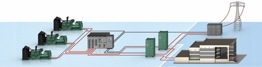
48Paralleled Generator Set EPSS Reprinted with permission from NFPA 110-2016, Standard for Emergency and Standby Power Systems, Copyright © 2015, National Fire Protection Association, Quincy, MA. This reprinted material is not the complete and official position of the NFPA on the referenced subject, which is represented only by the standard in its entirety which can be obtained through the NFPA web site at www.nfpa.org. 49
Utility Outage with Single Generator
Set System – Sequence of Events
1) ATS control detects failure of normal source
                                                                0 – 1 Seconds based on
2) ATS programmed time before next step
                                                                       application
3) ATS control sends start signal to generator set control
4) Generator set control initiates engine start sequence
                                                               4 – 8.5 Seconds based on
5) Generator set engine starts
                                                              generator set configuration
6) Generator set reaches “Ready to Load”
7) ATS transitions from normal to neutral position
                                                               0.5 – 1.5 Seconds based on
8) ATS transfer time delay
                                                             transfer switch and application
9) ATS transitions from neutral to emergency position

                                                                                            50
Utility Outage with Multiple Generator
Set System – Sequence of Events
1) ATS control detects failure of normal source
2) ATS programmed time before next step 0 – 1 Seconds based on
application
3) ATS control sends start signal to generator set control
4) Generator set control initiates engine start sequence
5) Generator set engine starts
6) Generator set reaches “Ready to Load”
7) Generator set paralleling controls begin “first start arbitration”
1) Generator set that “wins” first start arbitration proceeds to
next step
2) All other generator sets must synchronize before proceeding
to the next step
8) Generator set paralleling circuit breaker closes
9) ATS transitions from normal to neutral position
10) ATS transfer time delay
11) ATS transitions from neutral to emergency position
51Utility Outage with Multiple Generator
Set System – Sequence of Events
1) ATS control detects failure of normal source
2) ATS programmed time before next step 0 – 1 Seconds based on
application
3) ATS control sends start signal to generator set control
4) Generator set control initiates engine start sequence
4 – 8.5 Seconds based on
5) Generator set engine starts
generator set configuration
6) Generator set reaches “Ready to Load”
7) Generator set paralleling controls begin “first start arbitration”
1) Generator set that “wins” first start arbitration proceeds to
next step
2) All other generator sets must synchronize before proceeding
to the next step
8) Generator set paralleling circuit breaker closes
9) ATS transitions from normal to neutral position
10) ATS transfer time delay
11) ATS transitions from neutral to emergency position
52Utility Outage with Multiple Generator
Set System – Sequence of Events
1) ATS control detects failure of normal source
2) ATS programmed time before next step 0 – 1 Seconds based on
application
3) ATS control sends start signal to generator set control
4) Generator set control initiates engine start sequence
4 – 8.5 Seconds based on
5) Generator set engine starts
generator set configuration
6) Generator set reaches “Ready to Load”
7) Generator set paralleling controls begin “first start arbitration”
1) Generator set that “wins” first start arbitration proceeds to 0.5 – 1 Second for first
next step generator set
2) All other generator sets must synchronize before proceeding 0.5 – 1 Second for each
to the next step
additional generator set
8) Generator set paralleling circuit breaker closes
9) ATS transitions from normal to neutral position
10) ATS transfer time delay
11) ATS transitions from neutral to emergency position
53Utility Outage with Multiple Generator
Set System – Sequence of Events
1) ATS control detects failure of normal source
2) ATS programmed time before next step 0 – 1 Seconds based on
application
3) ATS control sends start signal to generator set control
4) Generator set control initiates engine start sequence
4 – 8.5 Seconds based on
5) Generator set engine starts
generator set configuration
6) Generator set reaches “Ready to Load”
7) Generator set paralleling controls begin “first start arbitration”
1) Generator set that “wins” first start arbitration proceeds to 0.5 – 1 Second for first
next step generator set
2) All other generator sets must synchronize before proceeding 0.5 – 1 Second for each
to the next step
additional generator set
8) Generator set paralleling circuit breaker closes
9) ATS transitions from normal to neutral position
10) ATS transfer time delay
0.5 – 1.5 Seconds based on
transfer switch and application
11) ATS transitions from neutral to emergency position
54Utility Outage with Multiple Generator
Set System – Sequence of Events
1) ATS control detects failure of normal source
2) ATS programmed time before next step
3) ATS control sends start signal to generator set control
10
4) Generator set control initiates engine start sequence
5) Generator set engine starts
6) Generator set reaches “Ready to Load”
7) Generator set paralleling controls begin “first start arbitration”
1) Generator set that “wins” first start arbitration proceeds to
Seconds
next step
2) All other generator sets must synchronize before proceeding
to the next step
8) Generator set paralleling circuit breaker closes
9) ATS transitions from normal to neutral position
10) ATS transfer time delay
11) ATS transitions from neutral to emergency position
Spec Note The smallest generator set on the generator set paralleling
bus shall have sufficient capacity to support all emergency loads. 55Utility Outage with Multiple Generator
Set System – Sequence of Events
1) ATS control detects failure of normal source
Related
2) ATS programmed time before next step Content NFPA 110 Time to Readiness
3) ATS control sends start signal to generator set control
10
PowerHour
4) Generator set control initiates engine start sequence White Paper
5) Generator set engine starts
6) Generator set reaches “Ready to Load”
7) Generator set paralleling controls begin “first start arbitration”
1) Generator set that “wins” first start arbitration proceeds to
Seconds
next step
2) All other generator sets must synchronize before proceeding
to the next step
8) Generator set paralleling circuit breaker closes
9) ATS transitions from normal to neutral position
10) ATS transfer time delay
11) ATS transitions from neutral to emergency position
Spec Note The smallest generator set on the generator set paralleling
bus shall have sufficient capacity to support all emergency loads. 56What are some of the commonly
misinterpreted or misapplied portions of
NFPA 110?
57NFPA 110 – Generator Set Subsystems
Temperature Maintenance
5.3.1 The EPS shall be heated as necessary to
maintain the water jacket and battery temperature
determined by the EPS manufacturer for cold start
and load acceptance for the type of EPSS.
Reprinted with permission from NFPA 110-2016, Standard for Emergency and Standby Power Systems, Copyright © 2015, National Fire Protection Association, Quincy, MA. This reprinted material is
not the complete and official position of the NFPA on the referenced subject, which is represented only by the standard in its entirety which can be obtained through the NFPA web site at www.nfpa.org. 58NFPA 110 – Generator Set Subsystems
Temperature Maintenance
5.3.1 The EPS shall be heated as necessary to
maintain the water jacket and battery temperature
determined by the EPS manufacturer for cold start
and load acceptance for the type of EPSS.
Spec Note Require the generator set vendor to provide an engine
jacket water heater sized appropriately for the engine. 59NFPA 110 – Generator Set Subsystems
Prime Mover Starting Equipment
5.6.4.1 Starting Systems. Starting shall be accomplished
using either an electric or a stored energy starting system.
5.6.4.3 Number of Batteries. Each prime mover shall be
provided with both of the following:
(1) Storage battery units as specified in Table 5.6.4.2
5.6.4.4 Size of Batteries. The battery unit shall have the
capacity to maintain the cranking speed recommended by
the prime mover manufacturer through two complete
periods of cranking limiter time-outs as specified in Table
5.6.4.2, item (d).
Reprinted with permission from NFPA 110-2016, Standard for Emergency and Standby Power Systems, Copyright © 2015, National Fire Protection Association, Quincy, MA. This reprinted material is
not the complete and official position of the NFPA on the referenced subject, which is represented only by the standard in its entirety which can be obtained through the NFPA web site at www.nfpa.org. 60NFPA 110 – Generator Set Subsystems
Prime Mover Starting Equipment
5.6.4.1 Starting Systems. Starting shall be accomplished
using either an electric or a stored energy starting system.
5.6.4.3 Number of Batteries. Each prime mover shall be
provided with both of the following:
(1) Storage battery units as specified in Table 5.6.4.2
5.6.4.4 Size of Batteries. The battery unit shall have the
capacity to maintain the cranking speed recommended by
the prime mover manufacturer through two complete
periods of cranking limiter time-outs as specified in Table
5.6.4.2, item (d).
Spec Note Require vendors to provide starting batteries sized
appropriately for use with the generator set configuration. 61One of the most important maintenance items
that deserves some extra attention is about
batteries. Can you tell us more about the key
role of batteries and how we can ensure
utmost reliability?
62Maintenance Testing Overview
8.1.1 The routine maintenance and operational testing
program shall be based on all of the following:
(1) Manufacturer’s recommendations
(2) Instruction manuals
(3) Minimum requirements of this chapter
(4) The authority having jurisdiction
Spec Note Require equipment vendors to provide electronic or hard-
copies of owner/operator manuals which include anticipated service
intervals.
Reprinted with permission from NFPA 110-2016, Standard for Emergency and Standby Power Systems, Copyright © 2015, National Fire Protection Association, Quincy, MA. This reprinted material is
not the complete and official position of the NFPA on the referenced subject, which is represented only by the standard in its entirety which can be obtained through the NFPA web site at www.nfpa.org. 63Parts Availability and Maintenance
8.2.4 Replacement for parts identified by experience as
high mortality items shall be maintained in a secure
location(s) on the premises.
8.3.2 A routine maintenance and operational testing
program shall be initiated immediately after the EPSS has
passed acceptance tests or after completion of repairs
that impact the operational reliability of the system.
Spec Note Require equipment vendors to maintain an inventory of
replacement parts and employ manufacturer trained service engineers
capable of servicing the emergency equipment.
Reprinted with permission from NFPA 110-2016, Standard for Emergency and Standby Power Systems, Copyright © 2015, National Fire Protection Association, Quincy, MA. This reprinted material is
not the complete and official position of the NFPA on the referenced subject, which is represented only by the standard in its entirety which can be obtained through the NFPA web site at www.nfpa.org. 64Starting Battery Maintenance
8.3.6 Storage batteries, including electrolyte levels or battery
voltage, used in connection with systems shall be inspected
weekly and maintained in full compliance with
manufacturer’s specifications.
8.3.6.1 Maintenance of lead-acid batteries shall include the
monthly testing and recording of electrolyte specific gravity.
Battery conductance testing shall be permitted in lieu of the
testing of specific gravity when applicable or warranted.
8.3.6.2 Defective batteries shall be replaced immediately
upon discovery of defects.
Spec Note Use starting batteries and battery chargers sized
appropriately for use with the generator set configuration as
recommended by the equipment manufacturer.
Reprinted with permission from NFPA 110-2016, Standard for Emergency and Standby Power Systems, Copyright © 2015, National Fire Protection Association, Quincy, MA. This reprinted material is
not the complete and official position of the NFPA on the referenced subject, which is represented only by the standard in its entirety which can be obtained through the NFPA web site at www.nfpa.org. 65Course Summary
Ask the Experts: NFPA 110 for Emergency Power Systems
NFPA 110, the Standard for Emergency and Standby Power Systems, sets the baseline for
emergency power system performance requirements and is critical to installation of nearly every
backup power system. This Ask the Experts session will address a number of key topics related to
NFPA 110 and will offer an opportunity to connect directly with power system experts at Cummins!
Topics addressed during this session will range from fuel and battery testing to Type 10 requirements
and complexities arising from paralleled power sources serving life safety loads. Bring your
questions and be prepared to engage in open discussion and Q&A with an expert panel.
After completing this course, participants will be able to:
• Identify key topics related to NFPA 110 impacting emergency power supply system design and
installation.
• Describe common pitfalls, challenges and misconceptions often encountered when validating
power system design.
• Recognize common code requirements mandated by NFPA 110 and their practical application.
66Additional Resources
Cummins White Papers
Maintenance is one key to diesel generator set reliability
Rated power factor tests and installation acceptance of emergency
and standby power systems
The 10-second start: NFPA 110 Type 10 starting requirements for
generator set applications
Design for safety and reliability-appropriate connection provisions for
generator sets
Cummins PowerHour (Live and On-Demand Webinars)
Testing Requirements of Emergency Power Supply Systems in
Critical Healthcare Facility
Specifying Generator Set Testing for Reliable Power Systems
NFPA 110 Type 10 Requirements for Emergency Power Systems
67Q&A
Please type your questions, comments and feedback in the Zoom Q&A window.
After the PowerHour, a complete list of questions and answers will be published on powersuite.cummins.com.
Michael Sanford Earnest Glaser Donald Sosa Trina Casbon Mark Taylor
Product Strategy and Sales Senior Sales Application Senior Sales Application Senior Sales Application Technical Advisor
Enablement Leader Engineer Engineer Engineer Cummins Inc.
Cummins Inc. Cummins Inc. Cummins Inc. Cummins Inc.
Your local Cummins contacts:
Ø AZ, ID, NM, NV: Carl Knapp (carl.knapp@cummins.com) Ø TX: Scott Thomas (m.scott.thomas@cummins.com)
Ø CO, MT, ND, UT, WY: Christopher Scott (christopher.l.scott@cummins.com) Ø OK, AR: Wes Ruebman (wes.ruebman@cummins.com)
Ø CA, WA, OR, AK, HI: Brian Pumphrey (brian.pumphrey@cummins.com) Ø TN, GA: Mariano Rojas (mariano.rojas@cummins.com)
Ø MA, ME, NH, RI, VT: Jim Howard (james.howard@cummins.com) Ø FL: Bob Kelly (robert.kelly@cummins.com)
Ø CT, MD, NJ, NY : Charles Attisani (charles.attisani@cummins.com) Ø NC, SC, VA: Bill Morris (william.morris@cummins.com)
Ø Northern IL, MI, IA : John Kilinskis (john.a.kilinskis@cummins.com) Ø Canada: Ian Lindquist (ian.lindquist@cummins.com)
Ø NE, SD, KS: Earnest Glaser (earnest.a.glaser@cummins.com) Ø PA, MD: Brian Cathcart (brian.cathcart@cummins.com)
Ø IL, IN, KY, MO: Jeff Yates (jeffrey.yates@cummins.com) Ø DE, MN, ND, OH, WI, WV: Michael Munson (michael.s.munson@cummins.com)
Ø LA, MS, AL: Trina Casbon (trina.casbon@cummins.com) 68Q&A
Please type your questions, comments and feedback in the Zoom Q&A window.
After the PowerHour, a complete list of questions and answers will be published on powersuite.cummins.com.
Please complete the brief survey after exiting the webinar!
Michael Sanford Earnest Glaser Donald Sosa Trina Casbon Mark Taylor
Product Strategy and Sales Senior Sales Application Senior Sales Application Senior Sales Application Technical Advisor
Enablement Leader Engineer Engineer Engineer Cummins Inc.
Cummins Inc. Cummins Inc. Cummins Inc. Cummins Inc.
Your local Cummins contacts:
Ø AZ, ID, NM, NV: Carl Knapp (carl.knapp@cummins.com) Ø TX: Scott Thomas (m.scott.thomas@cummins.com)
Ø CO, MT, ND, UT, WY: Christopher Scott (christopher.l.scott@cummins.com) Ø OK, AR: Wes Ruebman (wes.ruebman@cummins.com)
Ø CA, WA, OR, AK, HI: Brian Pumphrey (brian.pumphrey@cummins.com) Ø TN, GA: Mariano Rojas (mariano.rojas@cummins.com)
Ø MA, ME, NH, RI, VT: Jim Howard (james.howard@cummins.com) Ø FL: Bob Kelly (robert.kelly@cummins.com)
Ø CT, MD, NJ, NY : Charles Attisani (charles.attisani@cummins.com) Ø NC, SC, VA: Bill Morris (william.morris@cummins.com)
Ø Northern IL, MI, IA : John Kilinskis (john.a.kilinskis@cummins.com) Ø Canada: Ian Lindquist (ian.lindquist@cummins.com)
Ø NE, SD, KS: Earnest Glaser (earnest.a.glaser@cummins.com) Ø PA, MD: Brian Cathcart (brian.cathcart@cummins.com)
Ø IL, IN, KY, MO: Jeff Yates (jeffrey.yates@cummins.com) Ø DE, MN, ND, OH, WI, WV: Michael Munson (michael.s.munson@cummins.com)
Ø LA, MS, AL: Trina Casbon (trina.casbon@cummins.com) 69Closing
Watch out for a follow-up email including: Upcoming PowerHour Webinars:
§ A link to the webinar recording and copy of the presentation April: Navigating UL1008 Withstand and
§ A certificate issuing one professional development hour (1 PDH) Close Ratings for Specifying and Sizing
Visit powersuite.cummins.com for: Transfer Switches
§ Sizing and specification development tools
§ PowerHour webinar recordings, presentations and FAQ
§ Additional Cummins continuing education programs
Check out our new podcast, Brightest Bulbs:
§ Learn about the latest innovations in energy and power
§ Subscribe wherever you get your podcasts, or the link above
Visit cummins.com/energy-iq and sign-up for communications to:
§ Receive energy insights
§ Read about energy technologies and trends
Please contact Michael Sanford if you have any questions related to the PowerHour webinar (michael.sanford@cummins.com) 7071 71
You can also read