"DEVELOPMENT SOLUTIONS FOR A SUSTAINABLE MOBILITY" - FEV
←
→
Page content transcription
If your browser does not render page correctly, please read the page content below

Issue 68                      FEV CUSTOMER MAGAZINE

                       "DEVELOPMENT SOLUTIONS
                       FOR A SUSTAINABLE MOBILITY"
     Zero-Impact
Combustion Engine

 Fuel Cell Systems
   for Heavy Duty
Applications: From
Concept to System
         Validation

 The 3.0L Duramax
 Diesel Engine Sets
    New Standards

Urban Air Mobility –
  A New Market for
Automotive Players
TABLE OF CONTENTS

    Dear Readers,
                                                                              PAGE 04                                    PAGE 24                            PAGE 32
    Sustainable drive systems are becoming increasingly important
    with the tightening of emission standards. The decision as to which
    sustainable drive system is best suited for the respective application
    depends on various factors. These include costs, efficiency and
    legal requirements.

    On this basis, FEV develops solutions for tomorrow's mobility for
    its customers. In this issue of SPECTRUM, we would like to present
    the latest results of our work, including under which conditions a
    climate-neutral combustion engine is possible.

    A current further development in the field of diesel engines is the
    3.0L Duramax for pickup trucks, which sets new standards with its
    low fuel consumption and impressive performance. In addition,
    we will use a concept vehicle to show how further potentials can
    be tapped for hybrid drives with predictive and automated driving        Predictive Functions in the              Fuel Cell Systems for Heavy         Urban Air Mobility – A New Market
    functions with regard to their energy requirements.                      HYBex3 Concept Vehicle                   Duty Applications: From Concept     for Automotive Players
                                                                                                                      to System Validation
    For heavy-duty applications, we examine the development and
    validation of fuel cell systems from the point of view of total oper-
    ating costs.

    How will future mobility develop into space? In the field of urban       01 SUSTAINABLE DRIVE SOLUTIONS                            02 RESEARCH AND DEVELOPMENT
    airspace transport, we show access potentials for companies in the
    automotive industry. Exciting (3D) lighting concepts and efficient
    data management round off the variety of topics covered in this          04         Zero-Impact
                                                                                        Combustion Engine                              36         Exhaust Gas Condensate for Self-
                                                                                                                                                  Contained Water Injection System

                                                                             12                                                        40
    SPECTRUM.
                                                                                        Mild-Hybrid-Diesel-Powertrain                             Carbon-Neutral Transport –
    We hope you enjoy reading this issue. Further information and news                  with a Pre-Turbine                                        with Synthetic Fuels
                                                                                        Exhaust Aftertreatment
    about FEV can be found at www.fev.com.

                                                                             18                                                        46
                                                                                                                                                  Stepcom®-2 Step Variable
                                                                                        Predictive Functions in the                               Compression Ratio System Integration
                                                                                        HYBex3 Concept Vehicle                                    and Industrialization

                                                                             24         Fuel Cell Systems for Heavy
                                                                                        Duty Applications: From Concept
                                                                                        to System Validation
                                                                                                                                       52         SCR on Filter Technology
                                                                                                                                                  for Off-Highway Applications

    Professor Stefan Pischinger                                              30         The 3.0L Duramax Diesel
                                                                                        Engine Sets New Standards                      56         Urban Air Mobility – A New Market
                                                                                                                                                  for Automotive Players

                                                                                                                                       60
    President and CEO of the FEV Group
                                                                                                                                                  Workflow-Based Information Management
                                                                                                                                                  for Powertrain Testing Facilities

                                                                             03 NEWS
                                                                                                                                       66         NVH-Requirements of Electric
                                                                                                                                                  Drive Units in the Vehicle Interior

                                                                             70         Efficient Data Management:
                                                                                        Cooperation Between
                                                                                        FEV and Microsoft

                                                                             74         Light in Sight: FEV Subsidiary
                                                                                        Develops Micro-Lens Array
                                                                                        for Automotive Applications

2                                                                                                                                                                                              3
01 SUSTAINABLE DRIVE SOLUTIONS Emission reduction
EMISSION REDUCTION
A
Development methodologies
ZERO-IMPACT further tightening of emission legislation with Euro7
is expected. FEV’s hypothesis for the key challenges FEV has developed extensive patented and patent-pending
COMBUSTION ENGINE of the next European emission legislation consist of
the following major topics:
development methods in the field of simulation, as well as
testing and aging of emission-relevant components, which
A general reduction of the gaseous emission limits make it possible to demonstrate high robustness and forecast
CO: 500 mg/km . HC: 50 mg/km . NOX: 35 mg/km accuracy at an early stage of development.
Non-allowance of auxiliary emission strategies that can
lead to high emissions
Particle number emissions measured down to 10 nm RDE emission simulation and
instead of 23 nm identification of worst case cycles
Incorporation of further emission Emission simulation at FEV is an essential pillar in
components limits for the lab tests the frontloading of development. Presented
Extension of the RDE legislation for the first time in 2016 at the Vienna
framework to incorporate Engine Symposium, and further refined
further emission since then, this modular FEV simula-
components and short tion toolchain based on the GT-Suite
driving trips software environment is now an
essential part of FEV development
FEV has investigated how ul- activities. Engine raw emissions are
timately even a zero-impact modeled based on stationary and
combustion engine could be transient measurement data from
achieved, causing less emissions engine and roller test benches. The
than those contained in the am- simulation models of the exhaust
bient air. In particular the following aftertreatment follow a map-based
targets have been set: approach. Still, discretization of the cat-
Emissions in WLTC alyst monoliths allows a good description
NOX: 40 µg/m³ (corresponds to of the warm-up behavior to take into account
approx. 0.03 mg/km) individual, temperature-dependent conversion rates.
PM (2.5): 25 µg/m³ (corresponds to approx. 0.02 mg/km) Figure 1 depicts the all relevant variables which are included in
the calculation of the conversion.
Compared to today's Euro 6d legislation, this means a reduc-
tion of NOX emissions by 99.9 percent and PM emissions by Knowledge of which vehicle- and powertrain-specific cycles can
99.2 percent. lead to the highest emissions is essential for reliable compliance
with all emission limits under RDE conditions. FEV has realized
an abstraction of such real driving conditions. The result is a deri-
vation of a concise number of parameters. This parameterization
allows machine learning techniques to be applied to identify the
worst case RDE cycles based on an analysis of a few hundreds
Temperature calculation
QReaction of simulated cycles. This methodology has meanwhile been
Exhaust mass flow successfully applied in many development projects.
TCat
Exhaust temperature
Efficiency TCat, Element i
calculation
Engine out emissions Reaction enthalpy
ηCO = f(TCat, SV, θ) calculation
Emissions
TCat ηHC = f(TCat, SV, θ) downstream QReaction = f
ηNOx = f(TCat, SV, θ) catalyst (Converted CO,
SV
HC, NOx)
Oxygen storage model θ
AFR upstr. Cat
θ=f λ nach Cat
TCat
(TCat, SV, AFRu Cat) θ Calculation scheme for the efficiency
SV
calculation in the catalytic converter
4 5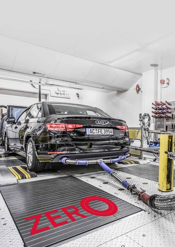
01 SUSTAINABLE DRIVE SOLUTIONS
Catalyst and gasoline particle filter Exhaust aftertreatment concept the level needed for sufficient conversion efficiency.
characterization to achieve zero-impact emissions Therefore, a secondary air pump is used to flow air
In the course of the development of FEV'S RDE emission sim- Five building blocks form the exhaust aftertreatment concept across the electrically heated catalysts prior to the
ulation methodology, it was identified that initially catalysts for achieving zero-impact emissions. engine start in order to heat up the main catalyst as
could hardly be modeled with sufficient precision. The reason 1. Optimization of NOX raw emissions during cat heating well. Figure 4 illustrates the heat up process of the final
for this lies in the mostly limited measurement data available 2. Exhaust aftertreatment with readiness immediately system configuration. The convective heat transfer can
from catalyst manufacturers and OEMs. However, for a precise after engine start clearly be seen in the lower half of the diagram. As soon
prediction of the emissions under RDE boundary conditions, 3. HC emission adsorption as the engine is started the higher exhaust mass flow
knowledge of the conversion rate at highest space velocities 4. Increase of total catalyst volume leads to even better convective heat transfer but at
and in a wide temperature range is of high importance. FEV 5. GPF with improved filtration efficiency the same time also a reduction in the temperatures.
there-fore developed its own equipment that can be used to
characterize catalysts under exactly these conditions. The system The individual building blocks are discussed below. Emissions can be further optimized by ensuring that
shown in Figure 2 is designed and proven for exhaust gas mass the catalyst system maintains a high temperature
flows up to those produced by turbocharged V12 engines to level. In a hybrid engine, this can be supported by the
measure the conversion efficiency at high mass flows and cold NOX optimized catalyst heating operation strategy and re-activation of the electrically
temperatures, such as they occur in a full load acceleration NOX aw emissions can be optimized by an adaptation of cat heated catalysts.
shortly after an engine start. heating calibration. For very retarded ignition timings, a high
amount of fuel is required to generate an IMEP that matches
the FMEP. This results in dethrottling and a lower rate of internal
Catalyst and gasoline particle filter aging EGR. The cylinder peak temperature increases and remains on
FEV has established a method for rapid aging of catalysts and a high level over a longer period of time. As a result, the NOX
GPFs, as well. For GPF aging, the burner test bench is modified emissions increase. To achieve a drastic reduction in NOX emis-
allowing oil to be burned in order to generate ash. Different sions, an optimized cat heating calibration would therefore use
methods have been investigated and finally oil injection was only a mild spark timing retardation. As a consequence, HC raw
chosen. FEV generated a cycle and oil dosing strategy that is emissions would increase, and additional measures need to be
able to reproduce similar aging characteristics as they are found implemented to address this.
during vehicle durability testing.
Electrically heated catalysts
Two electrically heated catalysts are integrated upstream of the
main catalyst (4 kW per disc, 8 kW in total). The metallic substrate
heats up rapidly achieving light-off after a few seconds. However,
an engine start followed by cold exhaust gas flowing across the
electrically heated catalysts would drop their temperature below
Temperature in Three-Way Catalyst / °C
800 800
Equipment for catalyst
characterization and
conversion efficiency 700 700
90 90
maps of an aged 50
Euro6d-TEMP three 600 600 70
way catalyst 70 50 30 10
500 500
30 10 TW, out 1 TW, in 1
400 400 θ1 m1
300 NOx emission conver- 300 HC emission conver- TW, in 2
TW, out 2
sion efficiency / % sion efficiency / % m2
200 200 θ2
0 100,000 200,000 300,000 0 100,000 200,000 300,000
Space velocity / (1 / h) Space velocity / (1 / h) Counterflow
heat exchanger Three-Way
θ3 Catalyst
Throttle
6
01 SUSTAINABLE DRIVE SOLUTIONS Emission reduction
CO2 mass flow / (g/s) Exhaust gas mass flow / (g/s)
4 20
3 15
Emission adsorption levels. This includes the volume of electrically heated catalysts. The final results for the optimal oper- 2 10
before catalyst light-off As a consequence, the space velocity at rated power is reduced ation strategy are depicted in Figure 8. 1 5
One way to achieve emission adsorption is by dedicated coatings. to values at which high conversion efficiency can be maintained The remaining NOX emissions –
0 0
In order to achieve a high adsorption efficiency, low temperatures even in aged conditions. although hardly visible – mainly result
HC emissions / ppm HC mass flow / (g/s)
are necessary. This matches with the lower incoming exhaust from the first seconds after engine start. 2000 0.020
gas temperatures due to advanced ignition timings during cat The oxygen storage capacity of the cat- 1500 0.015
heating. A metal substrate is considered since this allows high GPF with improved filtration efficiency alyst is completely filled at that time
1000 0.010
thermal inertia and thus low temperature increase in the first Best-in-class Euro 6c and Euro 6d-TEMP engines without GPF and initial rich operation is required
seconds of engine operation and an even distribution of the already achieve PM emissions in WLTC of only 0.12 – 0.28 mg/km. to purge the catalyst before full NOX 500 0.005
secondary air mass flow to the inlet face of the electrically heated Compared to the zero-impact target of 25 µg/m³ (approx. 0.02 conversion efficiency is achieved. In 0 0.000
catalyst. With a temperature limit of 850 °C the adsorption catalyst mg/km), there is the need for a further PM emission reduction the remaining part of the WLTC, NOX NOx emissions / ppm NOx mass flow / (g / s)
400 0.020
dictates the position of the exhaust aftertreatment system to be by 83 – 93 percent. This can well be achieved with a second emission slips remain minimal. The
not closed coupled which in turn has benefit regarding thermal generation GPF. 300 0.015
aging. Figure 5 shows a comparison of cat heating with and 200 0.010
without HC adsorption, in this case downstream of the catalyst. 100 0.005
Final results and outlook
0 0.000
For exhaust aftertreatment systems targeting at catalyst pre-heat- The outlined exhaust aftertreatment system is finally assessed
CO emissions / % CO mass flow / (g / s)
ing with a burner instead of electrically heated catalysts, the in combination with a 2.0 l 4-cyl. turbocharged GDI engine in a 0.8 0.100
adsorption of the burner emissions via a small carbon canister plug-in hybrid configuration. Figure 6 shows the final exhaust 0.6 0.075
positioned downstream of the catalyst might be a good solu- aftertreatment system.
0.4 0.050
tion as well.
Extensive DoE investigations have been performed in order to 0.2 0.025
achieve the zero-impact emission level while minimizing the fuel Raw emission results 0.0 0.000
Increased catalyst volume consumption penalty that arises from the electric pre-heating in steady-state cat 15 10 5 0 -5 10 -15 -20 -25 -30 15 10 5 0 -5 10 -15 -20 -25 -30
The catalyst volume is increase by 30 percent of the catalysts. Figure 7 depicts the correlation between the heating operation mode Spark advance / 0 CA BTDC Spark advance / 0 CA BTDC
compared to the Euro 6d-TEMP base-line electrical pre-heating energy and all resulting gaseous emissions.
E-catalyst
which is already using a bigger catalyst Valid points fulfill the zero-impact target of NOX emissions lower
Support brick E-catalyst Main catalyst
volume compared to former Euro 6b/c than 40 µg/m³ as well as a balanced SOC of the battery at the
1000
end of the cycle. The optimum for meeting the zero-impact target 900
800
at best possible fuel consumption is found slightly below 0.4 700
600
kWh. HC and CO emissions remain well below FEV's anticipated 500
400
Euro 7 limits. But, due to the concept, those emissions are not 350
300
as drastically reduced as the NOX emissions. 275 Temperature /
Time 250
°C
225
Heat up process of 200
175
the exhaust aftertreatment 150
system with electrically 125
100
heated catalysts 75
EV HAS DEVELOPED
F 50
25
EXTENSIVE DEVELOP- Length
MENT METHODS IN THE THC tailpipe emissions / ppm
FIELD OF SIMULATION, 2,500
AS WELL AS TESTING AND HC emissions
with adsorption
2,000
AGING OF EMISSION-
1,500
1,000
RELEVANT COMPONENTS, 500
WHICH MAKE IT POSSIBLE 0
TO DEMONSTRATE HIGH THC absorption efficiency of activated carbon trap / %
ROBUSTNESS AND 100
FORECAST ACCURACY
75
50
25
0
TWC + GPF 0 1 0 2 0 3 0 4 0
8 TWC + GPF + Activated carbon trap
Time / s 9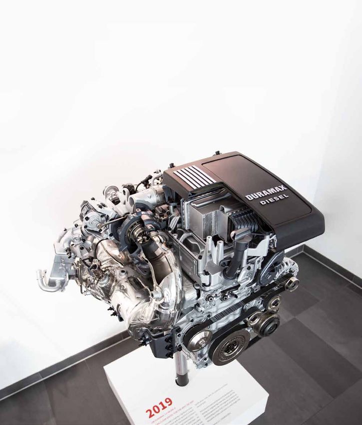
01 SUSTAINABLE DRIVE SOLUTIONS Emission reduction
E-catalyst + Temperature / °C Power / kW
electrically heated catalysts are re-activated Adsorption support GPF 800 12
brick E-catalyst system: Energy Power
Energy / kW
for short intervals during the cycle to ensure 600
8
the temperatures stay on a sufficiently high 400
Main catalyst 200 4
level at all times. Fuel consumption increases 0
TTWC, avg TInlet, BTWC
0
by 4.3 percent compared to the Euro 6d-TEMP CO massATWC / g battery energy content / kWh
baseline. 15 1.6
Secondary air pump EU7 limit
η CO / %
10 1.4
Cum. masse Conver. efficiency η
The zero-impact emission concept presented 5 1.2
Final exhaust aftertreatment system
here is extremely biased towards achieving 0 1.0
minimal NOX emissions. For the fulfillment of HC masseATWC / g Vehicle speed / (km / h)
1.5 150
"just" the Euro 7 emission limit, several concep- EU7 limit
η HC / %
1.0 100
tual adaptations are possible, e.g. reduction of
0.5 50
the number of electrical heated catalysts from CO ATWC / (g/km) Fuel consumption / (I / 100 km)
0.4 8.0 0.0 0
two to one. Moreover, the adsorption catalyst
NOx masseATWC / g 0 200 400 600 800 1,000 1,200 1,400 1,600 1,800
could be eliminated, allowing the entire cata- 0.3 7.5 0.9 EU7 limit Time / s
lyst system to be re-located back to a closed
η NOx / %
0.6
coupled position. 0.2 7.0
0.3
0.1 6.5 0.0
0 200 400 600 800 1,000 1,200 1,400 1,600 1,800
0.0 6.0 Time / s
HCATWC / (mg / km) NOxATWC / (mg / km) Final results with optimized e-catalyst
40 100 and hybrid operation strategy
30 10
By
20 1 Summary
Matthias Thewes · thewes@fev.com
Andreas Balazs · balazs@fev.com Zero-impact emissions are possible
10 0.1
Surya Kiran Yadla · yadla@fev.com To achieve them, the exhaust gas aftertreatment
0 0.01 Michael Görgen · goergen_m@fev.com needs to operate on high conversion efficiency as soon as
0.2 0.3 0.4 0.5 0.6 0.2 0.3 0.4 0.5 0.6 Jörg Seibel · seibel_j@fev.com the engine is started
Johannes Scharf · scharf@fev.com > Electrically heated catalysts in combination with
Electrical energy consumption for catalyst heating / kWh
Model points Valid points Optimum convective heat transfer prior to the engine start is identified
as one possible enabler for this
DoE results showing correlations between gaseous emissions and >H
C emission adsorption can support low NOX emissions by also
fuel consumption vs. the electrical energy used for catalyst heating
allowing to apply an adapted catalyst heating calibration
> Second generation GPFs enable a high filtration efficiency
Further improvement of the system is possible with even higher
convective heat transfer
The exhaust aftertreatment concept can be degraded
for purely meeting Euro 7 requirements
FEV has established the required know-how to
support you in the development of your next
generation exhaust aftertreatment system
10 11
01 SUSTAINABLE DRIVE SOLUTIONS Mild-Hybrid Diesel
MILD-HYBRID DIESEL
MILD-HYBRID-DIESEL-
T
he main concept was to locate compared to a conventional arrange- the exhaust system heats up, a thermal
the exhaust aftertreatment sys- ment (Figure 2). The introduction of a lag and overall temperature offset is seen
POWERTRAIN WITH A PRE-TURBINE tem (EATS) directly downstream
of the exhaust manifold, but up-
48V electric system to the vehicle enables
the incorporation of a pre-turbine after-
as a result of the higher thermal mass
upstream of the turbine. The heat loss
EXHAUST AFTERTREATMENT stream of the turbine as shown in Figure
1, so that the best CO2 reduction potential
treatment system via the integration of
an e-TC which compensates the loss of
profile over the PT-EATS leads to a cal-
culated cumulative enthalpy loss of ~ 4
and the best aftertreatment performances pressure and temperature caused by the percent over a WLTC (Figure 2). In order
The potential to achieve a simultaneous reduction in both NOx and CO2 emissions via can be achieved simultaneously. increased thermal inertia of the PT-EATS. to maintain the boost pressure levels in
fitting of a pre-turbine exhaust aftertreatment system (PT-EATS) in combination with a such low enthalpy phases, the electric
mild-hybrid concept was investigated via simulation. The main engine and hybrid system The engine hardware and PT-EATS were In the early phases of operation, the tem- turbocharger generates additional boost
hardware were specified and thereafter, the operating strategies for recuperation and designed and optimized via simulation perature before turbine is significantly pressure, it is also used to recuperate
turbocharger control were determined to enable the system to meet a defined tail- to identify the best layout of the catalysts lower than without the PT-EATS, owing excess energy whenever possible.
pipe NOX emissions value of 40 mg/km with a conformity factor (CF) of 1 over all and to quantify the potential benefits for to the increased thermal mass, but as
real-world driving cycles. The performance and drivability of the demonstrator CO2 and NOX emissions reduction. The
are defined to be equivalent to the 48V system, made up of a belt starter
base vehicle. generator (BSG) with the associated Urea Injector 1
eTurbo
VGT Urea Injector 2
control components, an electric assisted S
C SCRF
turbocharger (e-TC) and the 48V battery R SCR
Mixer
Mixer
as well as PT-EATS, were integrated to
the existing engine model. The simula- DOC PreTurbo Underfloor
Filter
tions optimized EATS component sizes to Cooler
Valve
achieve successfully the integration within LP-EGR
Cooler Valve
the engine bay. The e-Turbo was dimen- HFM Air Filter
AC
HP-EGR WCAC
sioned in GT Power and moreover the
BSG
EGR strategy was optimized to meet the DC Throttle Throttle
DC 2.0 L I4 EU6c
extremely low engine-out NOx emission DC
430 Nm @ 1750 rpm
48 V 12 V
targets. Furthermore, the recuperation Li-lon Lead-Acid 132 kW @ 4000 rpm
potential was established by using the Battery Battery HCU
simulation model. The original exhaust
manifold was rotated 180 °C to enable Pre-turbine aftertreatment system and 48V powertrain setup
the integration of the turbocharger and
a larger EGR cooler was inserted to allow
EGR to be used during full-load oper- Temperature at TC inlet / 0C
600 3.0 .107
ation. Additional design modifica-
tions were made to the intercooler 500 2.5 .107
bracket, the water lines and air
lines to allow the complete 400 2.0 .107
packaging within the engine
bay of the chosen J-Segment 300 1.5 .107 cum.
demonstrator vehicle. enthalpy / J
200 1.0 .107
Enthalpy impacts 100 5.0 .106
Placing the aftertreatment 0 WLTC 0.0 .100
system upstream of the
turbine results in an altered 0 200 400 600 800 1,000 1,200 1,400 1,600 1,800
enthalpy and thermal inertia Time / s
profile over the turbocharger
Temperature, EATS after TC Temperature, EATS before TC Enthalpy, EATS after TC
Enthalpy, EATS before TC Boosting required Recuperation possible
Temperature behavior and enthalpy input at the turbocharger
12 13
01 SUSTAINABLE DRIVE SOLUTIONS Mild-Hybrid Diesel
BSFC / g/kWh Pumping mean effective pressure v/ bar 6% 3% 30 % Fuel penalty as function of different
280 - 0.30
EATS volumes and EGR concept
- 0.35 rel. fuel 120
270 penalty by
- 0.40 e-TC boosting / 100
260
- 1.8 % - 3.3 % 100 %
- 0.45 80
250
- 0.50
60
240
- 0.55 + 32 – 44 %
230 40
- 0.60
220 20
- 0.65
- 1.1 %
- 0.3 %
210 - 0.70 0
0 125 250 375 500 625 750 875 1,000 0 125 250 375 500 625 750 875 1,000 EATS volume /L 4,5 L 3L 2,4 L 3L
mech. power / W HP-EGR only HP & LP-E-GR
e-TC recuperation BSG recuperation 4 bar, 2000 U / min 11 bar, 2000 U / min
Comparison of recuperation strategies at 2 part load points
pump losses, as seen in Figure 3, right. It there was minimal benefit to upsizing the acceleration time increases to 13.0 s, package space. All the above variables on the difference between desired and
Recuperation potential should be noted however that increasing the e-TC as the electrical boost required confirming that an e-Turbo is required. An were combined to create an optimised actual turbine torque. An additional
The recuperation potential of the sys- recuperation increases fuel consumption during transient operation would be in- increase in the E-machine power above air path strategy. Combining LP and HP- e-boost control factor is introduced to
tem was investigated at two part load as additional power is needed to generate creased so a smaller turbine was chosen. 11 kW showed no significant reduction in EGR, with a comparatively small turbine balance and adjust the responsiveness of
operating points, shown in Figure 3. The the same effective power. The key criteria in determining the size response time (9.0 s to 9.4 s) as accelera- and an 11 kW electric motor allows for the model-calculated torque demand to
comparison of the brake specific fuel con- of the e-machine used is the transient tion was limited by the electrical machine the lowest possible boost requirement the e-machine against the electric energy
sumption for 2 recuperation strategies response behavior of the vehicle. An speed to 180000 min-1. during transient driving conditions. The consumption. The fuel consumption pen-
was investigated and shown in Figure 3. Turbocharger sizing acceleration from a standstill to 100 km/h additional energy requirement for this alty and NOx engine-out emissions as a
Recuperation at the turbocharger via VGT The sizing of the e-TC was considered, as a was simulated with different sizes of e-TC configuration over a WLTC was approx. function of the e-boost control factor are
is compared with the extraction of the larger turbine could reduce fuel consump- to see which could achieve a comparable EGR strategy 52 Wh when omitting recuperation at the shown, in Figure 6 for the WLTC.
same power over the BSG via an operating tion via optimized pumping losses, but, acceleration behavior to the base vehicle Regarding the potential to reduce the BSG or e-Turbo.
point load shift. The latter strategy shows as typical passenger car driving scenarios (8.7 s in the sprint to 100 km/h). These cost and complexity of the EGR circuit, When applying small e-boost control
a more energy-efficient path by up to 3.3 are not significantly impacted by pumping simulations are seen in Figure 4. Illustrat- the use of an HP-EGR-only strategy was factors, the electric machine only sup-
percent, as closing the VGT increases the loss based fuel consumption penalties, ing that without electrical boost support, investigated which would consist of recu- Air path control ports during very high differences be-
perating excess exhaust gas energy, while The electrical VGT turbocharger requires tween desired and actual turbine torque,
controlling the VGT position to achieve a dedicated control strategy to optimize while for higher control factor values, the
Speed / kmh TC speed / krpm e-TC boosting / kw
120 210 18 the required back pressure to drive higher the different operating states. For this con- e-machine supports for smaller deltas
6kW eTC
180 16
11kW eTC
EGR rates at comparable boost pressure. cept configuration, the electric machine is in turbine torque. As such, the NOx en-
100 150 14
12 17kW eTCn The results showed, that including the mainly used for transient support during gine-out emissions are reduced at higher
80 150
120
10 PT-EATS w/TC LP-EGR path reduces the required elec- boost pressure build-up and recuperation e-boost control factor values, whereas
9.4 8
60
9.0 90 6 Base vehicle trical energy over the WLTC by about 30 during deceleration or in overrun oper- the fuel consumption increases signifi-
13.0
40 60 4 percent, therefore both HP- and LP- EGR ation. The conventional boost pressure cantly in consequence of the increased
8.7 10.3
30 2
20 0 0
are used. As the PT-EATS volume was control for the VGT was extended with electric power demand. These trends
0 2 4 6 8 10 12 14 0 2 4 6 8 10 12 14 0 2 4 6 8 10 12 found to show only minor impacts on an advanced model-based control for the were combined to determine the target
Time / s Time / s Time / s
the fuel consumption, compared to the power, respectively torque of the electric operation area.
Simulation of acceleration from standstill to 100 km/h EGR strategy influence, Figure 5, the EATS machine. In this approach the torque of
volumes were chosen to fill the available the electric machine is calculated based
HE KEY CRITERIA IN DETERMINING THE SIZE
T
OF THE E-MACHINE USED IS THE TRANSIENT
RESPONSE BEHAVIOR OF THE VEHICLE
14 15
01 SUSTAINABLE DRIVE SOLUTIONS Mild-Hybrid Diesel
Fuel penalty @ Engine-out NOx /
const. TP-NOx / % mg / km
12
Target
area
400
S THE RECUPERATED
A
20 380
ENERGY EXCEEDS THE
8 360 ELECTRICAL ENERGY
6 340 CONSUMPTION, APPROX.
4 320 30 PERCENT IS USED TO
2 300 CHARGE THE 48V BATTERY
0 280
0 20 40 60 80 100
e-boost control factor / %
The balance of the electrical energy within the 48V system over
the WLTC is shown in Figure 8. Recuperation takes place almost
exclusively by the BSG, whereas the energy consumption is split in
roughly equal parts between the supply of the consumers in the 12V
network and to support the electrical boosting. As the recuperated
energy exceeds the electrical energy consumption, approx.
30 percent is used to charge the 48V battery.
WLTC Schematic architecture of
Fuel consumption penalty the investigated concept
and NOx engine-out emissions 128
as a function of the e-boost
control factor.
- 437 Electric energy balance (Wh)
State of charge
309 Consumption
Recuperation
1 % by e-TC BSG boost 1 %
Overall hybrid strategy optimization liable supply for the on-board 12V network under all operating
The additional benefits of the 48V mild-hybrid system architecture conditions and simultaneously maximizes the potential of the by BSG 99 % by 12 V consumer 51 % 48 % e-TC boost
shown in Figure 7 were evaluated. A 48V belt starter generator various 48V components to balance transient support during
replaces the conventional 12V generator, a 48V battery with a boost pressure build-up and recuperation potential at engine
capacity of 0.5 kWh, and the electrically supported electrical VGT overrun operation and high enthalpy flow upstream turbine.
turbocharger were integrated with the 12V on-board power supply Electric energy Electric energy
recuperation consumption
provided via a bidirectional DC/DC converter. When optimizing
the control of the electrical VGT turbocharger, a priority manager
governs available power for the different consumers, based on
ICE
the current state of the electric system. The simulation model
uses a higher-level energy management strategy to ensure re- AT The second part of this paper in an upcoming SPECTRUM issue By
12 V
Starter
BSG will detail the PT–EATS system optimization and the overall Dr. Lynzi Robb
eTC
12 V-
DC 12 V Net
system performance over key RDE cycles. robb@fev.com
Battery
DC
48 V
48 V-
Battery
Balance of electrical energy in the 48V system
16 17
01 SUSTAINABLE DRIVE SOLUTIONS                                                                                                                    Efficient Mobility

     EFFICIENT MOBILITY

     PREDICTIVE FUNCTIONS IN
     THE HYBEX3 CONCEPT VEHICLE

                                                                                                        C
     The hybridization of powertrains is an important step toward efficient and clean                              ombined with the development of predictive and automat-
     mobility. In particular, the possibility of shifting the operation of the combustion                          ed driving functions, further potentials can be tapped. The
     engine to ranges with a higher efficiency level and representing purely electric                              key factor for an actual reduction of the energy require-
     driving modes is one of the main advantages of hybrid drives. This shifting of the                            ment under real driving conditions is a precise forecast
     load point can be further optimized on the basis of route data that includes the                   of the future development of a traffic situation. This forecast can
     expected vehicle speed as well as the road gradient, and is considered to be the                   be based on a multitude of potential sources, such as sensor data,
     state of the art with regard to modern hybrid drives                                               high-resolution maps, and vehicle communication, whereby all the
                                                                                                        data is fused into a comprehensive environmental model.

                                                                                                        Based on the information from this model, the longitudinal guid-
                                                                                                        ance of the vehicle and the powertrain control can be optimized.
                                                                                                        In cooperation with the Institute for Combustion Engines of RWTH
                                                                                                        University Aachen, Germany, FEV has developed a function structure
                                                                                                        that is capable of using a multitude of potential data sources. This
                                                                                                        creates a solution space for predictive speed profile optimization.
                                                                                                        This speed profile can then be used in order to optimize the operation
                                                                                                        of torque distribution between the hybrid components.

                                                                                                        The function structure was integrated in a hybrid prototype vehicle
                                                                                                        constructed jointly with DENSO. A robust, real-time model predic-
                                                                                                        tive control algorithm is used in order to optimize the longitudinal
                                                                                                        guidance of the vehicle.

                                                                                                        The HYBex3 concept vehicle
                                                                                                        The HYBex3 (”HYBrid power exchange 3 modes“) vehicle was devel-
                                                                                                        oped in order to determine the impact of a cost-effective DHT trans-
                                                                                                        mission concept on the driveability of the vehicle and test it under
                                                                                                        real conditions. It was developed jointly with DENSO AUTOMOTIVE
                                                                                                        Germany. The base vehicle is a MINI Cooper with a turbocharged
                                                                                                        100 kW three-cylinder combustion engine. The serial transmission
                                                                                                        was replaced with the hybrid transmission to be examined, which
                                                                                                        was specially developed for the application case.

                                                                                             HE HYBEX3 VEHICLE WAS DEVELOPED IN
                                                                                            T
                                                                                            ORDER TO DETERMINE THE IMPACT OF A
                                                                                            COST-EFFECTIVE DHT TRANSMISSION CONCEPT
                                                                                            ON THE DRIVEABILITY OF THE VEHICLE AND
                                                                                            TEST IT UNDER REAL CONDITIONS

18                                                                                                                                                                               19
01 SUSTAINABLE DRIVE SOLUTIONS Efficient Mobility
The powertrain topology is equivalent to a mixed hybrid equipped combustion engine, without compromising the overall dynamic Predictive functions Further information can be obtained from In contrast, the camera sensor can only
with two electric engines (EE) in a P2/P3 layout. The P2 machine of the powertrain. The operating strategy was optimized with a The function structure developed for pre- the on-board navigation systems, which provide estimates regarding the relative
is located between the electrohydraulically powered clutch and Design of Experiments. For this purpose, the parameters of the dictive longitudinal dynamic control is indicate speed limits, road gradients and speed and the distance, but can precisely
the two-stage spur gear component. The synchronization ele- stop-start strategy of the combustion engine were optimized designed in such a way that a multitude of curvatures as well as, potentially, inter- determine whether the detected object
ments are also actuated electrohydraulically. The P3 machine is simultaneously with the parameters of the battery charging data sources, optimization routines, and section data for the most probable path is in the same lane as the vehicle under
positioned at the transmission output and therefore has a fixed strategy. For the final parameterization, a compromise between powertrain structures can be represented of the vehicle via an "electronic horizon". consideration. After the fusion of several
transmission ratio to the wheel. the layouts for different driving cycles was selected. in said function structure. If the navigation system is connected to data sources, an aggregated object list
the internet, data on average speeds along is created, which only contains valid and
Various operating modes can be represented with this DHT The distribution of the torques of the two electric engines, The first step is an aggregation and fusion the planned route and traffic jams can relevant data for all detected objects, and
transmission. For purely electric driving, the combustion engine both in parallel operation and in fully electric driving, is deter- of the available data into an environmen- be provided. generates a corresponding environmental
is stopped and the clutch is opened. Electric engine P2 can mined by an online optimization patented by FEV. The search tal model, followed by a prediction of model.
therefore be operated in both transmission stages. In addition algorithm varies the torque distribution until the energetically the traffic situation. This enables an op- Additional data can be obtained through
to a high starting torque in the first gear, this enables a maximum optimal case is found. In doing so, both the battery limits and timization of the speed profile. On the the future connection of vehicles using 5G Before an optimization of the vehicle
vehicle speed of 140 km/h in the second gear. the power limits of the electric engines are taken into account basis of that, an acceleration control of or ETSI ITS G5. This Vehicle-to-everything trajectory can be carried out, there must
for the current situation. the vehicle is carried out. The planned (V2X) communication should include, be a forecast of the development of the
In hybrid operation, serial or parallel driving is possible. In parallel speed profile can also be used in order among other things, the positions, di- current situation. This forecast is based
operation, one of the two gear sets is engaged. In serial operation to adjust the charging status strategy. If rection, and speeds of other vehicles, as on the relevant objects that the environ-
mode, the transmission is shifted to neutral. The combustion the desired charging performance is de- well as the layout of intersections and the mental model provides. The first step is
EMS w / 2 Gear 3-Cylinder
engine is then exclusively connected to electric engine P2 while reduction gear transmission gasoline ICE Front axle termined, the torque distribution between status of traffic light systems. The vehicle the determination of the speed limit along
electric engine P3 operates the wheels. All gear changes are the powertrain components is carried out communication can therefore provide the prediction horizon. Based on that and
synchronized entirely electrically, so that the friction clutch can P2 EM on the basis of said performance and the data that goes beyond the horizon de- the current condition of detected vehicles
remain closed even in hybrid operation. The serial operation in wheel torque requirement. tectable via on-board sensors. driving ahead, the speed and position
the low speed range and the parallel operation at higher speeds trajectory of these vehicles is forecast.
enable a significant increase of the system efficiency level. The precise forecast of the current traffic Since the same object can therefore be
situation requires the aggregation of all detected multiple times by various data On the basis of this, a solution space is
The operating strategy provides for the combustion engine available data. This includes, for instance, sources, the data aggregation must also spread out in which the downstream op-
being operated at a very low dynamic and the implementation RADAR sensors, LIDAR sensors, or opti- include a functionality for data fusion. This timization algorithm can operate. The
P3 EM
of fast load changes by the electric path. The transmission ratios cal cameras that traffic participants can is especially advantageous for hardware function structure developed by FEV and
enable a significant reduction of the rotational speed of the identify with the help of image recogni- setups with different types of sensors, the Institute for Combustion Engines
HYBex3 transmission topology tion techniques. Usually, these sensors e.g. a RADAR sensor and camera sensor. enables the implementation of differ-
indicate the type (passenger car, truck, The RADAR sensor can precisely define ent algorithms to this end. Depending
pedestrian, etc.), the relative positions the distance to and the relative position on the requirement, simple, rule-based
and, potentially, the relative speed of the of a vehicle driving ahead, but cannot approaches, as well as model predictive
detected objects. determine the lateral position of the ve- control or discrete dynamic programming
hicle in relation to the road markings. methods can be represented.
Input Data handling and interpretation Powertrain control optimization
HYBex3 concept vehicle
based on a MINI Cooper Longitudinal
Situation Acceleration ICE torque
Camera trajectory
prediction control request
optimization
Data
aggregation
Electronic Torque split EM1 torque
into
horizon optimization request
environment
model
V2X, Charge power EM2 torque
SoC strategy
Radar … calculation request
Function architecture for predictive functions
20 2101 SUSTAINABLE DRIVE SOLUTIONS Efficient Mobility
Input Data aggregation Situation prediction
Data fusion Fellow vehicle Relevant fellow Fellow Position
Camera Distance / m Velocity / (km / h) Acceleration / (m / s2)
data selection prediction solution space 400 50 1
40 0.5
300
0
Electronic Traffic light Traffic light Green phase 30
horizon data selection selection 200 - 0.5
20
-1
100 10 - 1.5
Road gradient
Radar, ... 0 0 -2
data
0 5 10 15 20 25 30 0 5 10 15 20 25 30 0 5 10 15 20 25 30
Time / s Time / s Time / s
Velocity
V2X Speed limits
solution space
POSITION VELOCITY ACCELERATION
Function architecture
for data aggregation and
situation prediction
Application in the vehicle
To test the function structure, a real time-compatible model predictive By
control (MPC) was implemented in the rapid prototyping control unit of Dr. Georg Birmes . birmes@fev.com
the HYBex3 concept vehicle and various test scenarios were carried out. In Dr. Rene Savelsberg . savelsberg@fev.com
a first demonstration, the functionality and real-time compatibility of these
scenarios for a predictive adjustment of the HYBex3 concept vehicle was Marius Wegener
proven. With an efficient implementation of the MPC using the qpOASES Prof. Jakob Andert
tool, an optimization of the speed curve for a horizon of 10 s can be carried Institute for Combustion Engines,
out within less than 100 µs. RWTH Aachen University, Germany
0.0 % 37.7 km / h - 0.4 m / s2
In the future, the modular design of the function structure can be used to Ulrich Schwarz
expand the forecast horizon of the vehicle – for instance, with traffic lights DENSO AUTOMOTIVE
ahead – or to represent predictive, automated driving functions such as Deutschland GmbH
Predictive Cruise Control (PCC). ACCELERATOR PEDAL VELOCITY ACCELERATION
Experimental validation of the functions on the test track
22 2301 SUSTAINABLE DRIVE SOLUTIONS Fuel Cell
FUEL CELL
FUEL CELL SYSTEMS FOR Use cases for fuel cell electric vehicles Although in the passenger car segment, higher quantities are
HEAVY DUTY APPLICATIONS: As fuel cell systems and batteries do not emit hazardous green-
house gases during their utilization, their implementation into
generally achieved, commercial vehicles could first possibly
experience greater market penetration of fuel cell electric pow-
FROM CONCEPT TO passenger cars, light commercial vehicles and heavy duty ap-
plications can contribute to the reduction of CO2 emissions
ertrains. However, compared to the passenger car segment, the
implementation of fuel cell systems in heavy duty applications
SYSTEM VALIDATION from the transport sector, if the hydrogen for their operation is
generated with e.g. electricity from renewable energy sources.
brings new challenges. One of the major challenges is the
required lifetime of approximately 20,000 h, which is almost
Compared to battery electric vehicles (BEV), fuel cell electric three times higher than for passenger cars.
Since the transport sector has not seen the gradual decline of CO2 emissions as other sectors vehicles (FCEV) allow for larger driving ranges, shorter refueling
have, it is more than ever at the forefront of public attention, as well as priority for research. times - comparable to the refueling process of vehicles with diesel
Particularly for the heavy duty (HD) transport with its high specific CO2 emissions, major research
and development programs are ongoing for the implementation of low- and zero-emission
or gasoline engines - as well as reduced powertrain weight, and
therefore higher payloads. SPECIALLY FOR HEAVY
E
powertrains. Not only does the reduction of the fleet’s average CO2 emissions to prevent high DUTY VEHICLES WITH
financial charges for exceeding CO2 emission limits, but also the system efficiency, durability,
reliability and total cost of ownership (TCO) need to be considered to find competitive
The decision as to which powertrain is the most suitable for an
application and use case depends on several factors such as
HIGH ANNUAL MILEAGE,
alternatives to internal combustion engines for heavy duty transport. costs, efficiency and durability. However, the focus must be on FUEL CELL ELECTRIC
the benefit to the customer. POWERTRAINS SHOULD
Exclusive usage of pure battery electric powertrains for heavy duty applications is not yet a
viable option, as large batteries are necessary, which lead to high powertrain weight, increased Considering driving range and vehicle weight, Figure 1 provides a
BE FAVORED
power demand and reduced payloads. That is why proton ex-change membrane fuel cells general overview about suitable electric powertrains for different
(PEMFC) in combination with smaller batteries represent a promising approach for heavy duty vehicles. Due to their high efficiency, but also lower power den-
vehicles with electric drives. sity, battery electric powertrains (BEV) are expected to be more
suitable for light duty vehicles with small driving ranges, whose
The Institute of Combustion Engines (VKA) of the RWTH Aachen University, Germany and FEV daily trips are primarily inner-city. For larger driving ranges and
Europe GmbH investigate, inter alia, the implementation of PEMFCs in transport applications. In heavy duty applications, fuel cell electric powertrains, supple-
order to assess alternative powertrains for commercial vehicles, the investigation of total cost of mented with small-size batteries for peak power and
ownership for different powertrains, considering different scenarios for electricity generation from re-cuperation (FC-HEV) should be
renewable sources, is important to make decisions on the development of future HD powertrain favored in partic-
systems.
The following details FEV’s and VKA’s development and validation of fuel cell systems
with advanced operating strategies for heavy duty applications up to 250 kWnet power
output. Fuel cell degradation mechanisms and their mitigation strategies
are introduced to optimize the hybrid operating strategy
and to prove durability and reliability of the
designed systems. The
importance of
TCO in the commercial
vehicle segment
A main technology driver within the commercial vehicle segment
has always been Total Cost of Ownership (TCO). Beneath the
ular, also with vehicle price and the resell value, the operational costs represent
regard to overall power- the most relevant factor of TCO. An FEV study on the TCO for dif-
train weight. A combination of a fuel ferent commercial vehicle segments analyzed various use cases
cell system and a medium-sized battery (FC- to determine whether conventional diesel powertrains, battery
PHEV) is often the most promising option. The question electric or fuel cell electric powertrains will have the lowest TCO
about where the sweet-spot of the fuel cell system power and in the future. Considering target driving profiles, as well as the
the battery power/capacity is, remains a subject of discussion mainstream fuel cell boosters and inhibitors, the study came
and is still a major focus of research. to the result that especially for heavy duty vehicles with high
24 2501 SUSTAINABLE DRIVE SOLUTIONS Fuel Cell
Fuel Cell Stack
Long
Distance Coolant Ion
Expansion tank pump
FC-HEV exchanger
Compressor Motor
Inverter Humidifier
FC-PHEV
Air filter Compressor Charge
air cooler
BEV
Muffler Throttle SoV
City Hydrogen storage
and supply module Drain valve
Purge valve
Dosage
Light Duty Heavy Duty TPRD valve Water
separator
H2-Tank
Pressure Jet pump
reducer CVM
Use cases for battery electric vehicles (BEV), fuel cell plug-in hybrid electric vehicles (FC-PHEV) H2 recirculation
and fuel cell hybrid electric vehicles (FC-HEV) module
TPRD Thermally activated pressure relief device
CVM Cell voltage measurement Hydrogen path
FCCU Fuel cell control unit Air path
annual mileage and occasional trips > 400 km, fuel cell electric as feedstock, their costs are a linear function of the hydrogen SoV Shut-off valve Coolant path
powertrains should be favored. Further-more, in zero emission costs. Currently, only hydrogen produced via steam reforming
zones, especially in cold regions, a stringent environmental policy, can compete with the low costs of conventional diesel fuel.
Simplified system layout of a fuel cell system concept
as well as a hydrogen price < 4 €/kgH2 can boost the implemen-
tation of fuel cell systems for heavy duty applications. The fuel To further reduce the TCO of fuel cell electric vehicles, the devel-
prices have a large impact on the operational costs. Especially opment and production costs of fuel cell systems also need to
for hydrogen, the future cost and price remains uncertain due to be taken into consideration. Due to the high required lifetime of Since the power demand varies with the application and use different phases starting with the requirements specification, and
the high dependence on the production process, energy source fuel cell systems for heavy duty applications, improving reliability case, the fuel cell stacks and their BoP components need to be the concept until the first tests and the final system validation.
and taxation. In Figure 2, the hydrogen costs depending on the and durability is of utmost importance to avoid the premature scaled. To reach cost efficiency for fuel cell electric vehicles in the At first, the FCEV is decomposed into its different subsystems,
primary energy source and production process, as well as the replacement of fuel cell stacks and auxiliary components, as low quantity commercial vehicle segment, synergies with fuel such as the hybrid system. Then it can be further decomposed
costs of petroleum based diesel fuel and several promising well as minimize unscheduled maintenance and downtimes. cell systems for passenger car into the traction battery and the
E-fuels are shown. Currently, most of the hydrogen is produced applications need to be utilized. fuel cell system, fuel cell stack
via steam reforming (fossil H2) with costs of approximately
0.6 to 2.9 €/kgH2. Aiming to establish green hydrogen, produced Scaling of fuel cell systems
A modular approach is desired
to avoid the new design of sev-
HE INTEGRATION OF
T and BoP components. These
subsystems can be further di-
via electrolysis, leads to costs of approximately 4.5 to 7.3 €/ and synergy effects eral BoP components or even SIMULATED COMPONENTS vided into their individual com-
kgH2, if wind is used as renewable ener-
gy source. Using photovoltaics as a
Fuel cell systems consist of several components which ensure
that the fuel cell stack is operated as optimally as possible. These
the whole system. On the other
hand, production costs need to
REDUCES DEVELOPMENT ponents, which are not shown
in Figure 5 for the sake of clarity.
renewable energy source, leads to so-called ‘Balance of Plant Components’ (BoP) can be assigned be considered, which are higher COSTS AND ACCELERATES For all the subsystems and their
costs of approximately 7.3 to 10 to the air path, fuel path, coolant path and high voltage system. for the modular approach than SYSTEM DEVELOPMENT components, the requirement
€/kgH2. Since the production of An exemplary layout of a fuel cell system is shown in Figure 3. for a scaled fuel cell system. By specification needs to be for-
most E-fuels requires hydrogen using scaled fuel cell systems, mulated in close consultation
it is also possible to reach higher system efficiency, since the with the customer. This has to be conducted not only on hard-
fuel cell system can be adapted optimally to the particular ware, but also on the software level. In this work, the focus will
application. Figure 4 shows that within the commercial vehicle be on the calibration of the fuel cell system during start-up and
Fossil H2 H2 from Wind H2 from PV segment, these scaling methods offer a flexibility in design and shut-down, and the system validation.
Fuel cost 450 OME3-5 (Trioxan Route) need to be investigated in detail. However, the key arguments
[€-ct / Liter 400 FT-Alcohol for the modular approach are the high carry-over rate from
Diesel equivalent]
350
OME1 (Me Oh Route)
Methan (200 bar) the passenger car segment, as well as the potential to achieve System validation for
300 Methanol increased reliability and durability of the fuel cell systems. By heavy duty applications
250 DME using several fuel cell systems, advanced operating strategies Especially the optimization of water management on cathode,
200 H2 (800 bar)
can be developed to run the different fuel cell stacks each on a as well as anode side, the optimal membrane humidifier size
150 Fossil Diesel: Incl. tax
for mineral oil & sales tax different constant load to reduce excessive voltage cycling and and the active and/or passive recirculation of hydrogen on the
100
Fossil Diesel: Netto mitigate degradation. anode side in combination with an improved purge and drain
50
logic are important aspects during calibration. The software
0
0 1 2 3 4 5 6 7 8 9 10 for the control of the entire fuel cell system (Fuel Cell Control
H2 Cost (€ / kg)
Development of fuel cell systems Unit, FCCU) needs to be calibrated so that in various operat-
for heavy duty applications ing points and during dynamic operation stack and system
Hydrogen costs depending on production process/energy source The V-Model for the development process of a fuel cell electric performance, operational stability and durability are ensured.
and related E-fuel and diesel fuel costs vehicle (FCEV) is represented in Figure 5. It is characterized by During calibration, the start-up and shut-down procedure of
26 2701 SUSTAINABLE DRIVE SOLUTIONS Fuel Cell
Application case Efficiency / %
70 1 Stack efficiency
Power range 30 – 70 kW 50 – 120 kW > 200 kW
System efficiency
60
0.8 Stack power
Stack platforms or System power
50
Synergies Off-Highway Passenger Cars 0.6
40
P / P Max.1 Stack
Possibilities of 30
0.4
system scaling Parallel arrangement of Combination of scaling and Completely scaled system
independent identical systems multiple usage of components 20
0.2
Full redundancy Partly redundancy Optimally adapted system 10
Lowest development costs Lowest costs (component-wise Lowest component unit costs Stack and
decision about multiple usage
or customized development 0 0 system performance
based on the expected quantities) 0.2 0.4 0.6 0.8 1
Highest production costs No redundancy
Potentially lower efficiency Potentially highest component
development costs
Key Blower representing all auxiliary components Stack incl. end plate
Real-time network for the investigations of the
Power demand for fuel cell systems in various commercial vehicle application cases advanced fuel cell electric powertrains
and scaling methods for fuel cell systems The real-time communication between different component test benches as By
shown in Figure 8, enables the further improvement of the fuel cell system Dr. Marius Walters
and hybrid system already in early development phases. The integration of walters@fev.com
the developed fuel cell system must be given special attention. evenly over a bleed resistance, fuel/air fronts and reverse current simulated components reduces development costs and accelerates system FEV Europe GmbH
This is illustrated in Figure 6. The implementation of diagnostic phenomena during following start-up procedures and related development. By setting up virtual powertrains, the interactions between
functions to detect malfunctioning components and ensure degradation mechanisms, especially the carbon corrosion of different components, the dynamic behavior in varying driving cycles, and the Johannes Buchmann
proper communication is as essential as the checks of cathode/ the catalyst support, can be reduced. advantages and disadvantages of different HV-topologies can be analyzed to buchmann@fev.com
anode valves and leakproofness. improve the control strategies on vehicle and fuel cell system level. Powertrains FEV Consulting GmbH
After the calibration and commissioning of the fuel cell system, with a fuel cell system power of up to 250 kW can be investigated, which are
To prevent the condensation of excess water during the shut- the performance and efficiency during normal operation is in- suitable not only for heavy-duty applications for road, but also for rail trans- Steffen Dirkes
down procedure, after the reduction of stack power, a drying rou- vestigated. System efficiencies between 41 at full load and more port. Especially for cold start studies, a climate chamber with temperatures Institute for Combustion Engines,
tine is conducted. In this way, the fuel cell system is well-prepared than 53 percent at part load are achieved as shown in Figure 7. reaching from -42 to 110 °C can be used within this framework. RWTH Aachen University, Germany
for longer downtimes even in cold environments. By inertizing
the cathode and dissipating the residual potential of the cells
Start-up produce
Start-up procedure
De
1 1
Fuel Cell Stack BoP Components 1 1
Functional principle of
co
Average cell voltage / V
Voltage
Voltage 3
Real-time Network
System off
m
0 0
the real-time network
0.8 0.8
System off
Fuel Cell System Current
Current
po
0.8 0.8
for the fuel cell electric
sit
Average cell voltage / V
0.6 0.6
procedure
Hybrid System Standby
l / l max
Standby 1 1
max
i
on
1 2 4 5
Average cell voltage / V
vehicle setup
0.6 0.6
I/I
Fuel Cell System + DC/DC Inverter + Electric Engine
0.4 0.4
max
Fuel Cell Electric Vehicle Cooling system scheck
Cooling system check
2 2
Idle
I/I
Idle
0.4 0.2 0.4 0.2
Start-up procedure
Cathode check
Cathode check 3
H2 + 02
procedure Start-up
3
0 0
Customer Value
0.2 0.2
Time
Time
Anode check
Anode check
4
4
Shut-down produce
Shut-down procedure
Fuel Cell DC/DC Electric
Re ecifi
1 1
0 0
Inverter
sp
Abstraction
qu cat
Warm up phase Time
5
System FCS
Single cell voltage / V
Engine
ses
Warm up phase 5
Average cell voltage / V
Operating Principle
ire ion
0.8 0.8
t ca
me
Normal operation 6
Normal operation 6 6
Tes
0.6 0.6
nt
Shut-down procedure
l / l max
Average cell voltage / V
Shut-down
Technical Solution
max
Part
Drying 7
Drying
load
I/I
7
DC Bus Virtual Shaft
0.4 0.4
Cathode inertization 8 7 Time
Cathode inertization
1 1
8
Idle Voltage
Industrialization
0.2 Voltage 0.2
Idle
Emergency shut-down 9 0.8
8 Current
Current
0.8
Differential +
0 0
Emergency shut-down 9 Time
Time
DC/DC
Average cell voltage / V
Traction
0.6 0.6
Deliverables Transmission
max
Battery BAT
I/I
0.4 0.4
0.2 0.2
V-Model of the FCEV development process Simplified illustration of the most important operational Hardware
with its decomposition into sub-systems states (left); stack voltage and normalized stack current
0 0
Traction Battery + DC/DC Transmission
Time
Simulated
during start-up (top right); stack voltage and normalized
stack current during shutdown (bottom right); zoomed
in view: minimum, maximum and selected cell voltages
during cathode inertization (measured data, plotted partly
schematically).
28 29You can also read