Dynamic optimization of snake robot with environment detection and analysis
←
→
Page content transcription
If your browser does not render page correctly, please read the page content below

IOP Conference Series: Materials Science and Engineering

PAPER • OPEN ACCESS

Dynamic optimization of snake robot with environment detection and
analysis
To cite this article: P Jeevanantham and J Daniel Glad Stephen 2018 IOP Conf. Ser.: Mater. Sci. Eng. 402 012019

View the article online for updates and enhancements.

                              This content was downloaded from IP address 46.4.80.155 on 01/09/2021 at 10:21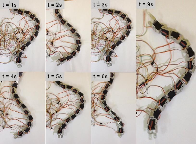
2nd International conference on Advances in Mechanical Engineering (ICAME 2018)            IOP Publishing
IOP Conf. Series: Materials Science and Engineering 402 (2018) 012019 doi:10.1088/1757-899X/402/1/012019
                                               1234567890‘’“”

Dynamic optimization of snake robot with environment
detection and analysis

                    P Jeevanantham* and J Daniel Glad Stephen
                    Department of Mechanical engineering, SRM Institute of Science and Technology,
                    Kattankulathur – 603203, Chennai

                    *
                        Corresponding authors: jeevan221093@gmail.com
                    Abstract. Recent developments of snake robots have seen increasing interest in the aid of robotic
                    systems to assist in disaster operations. This paper presents a design of snake robot for dynamic
                    optimization to maneuver in various environments. The robot makes utilization of the friction
                    between the body of the robot and the environment to move in. The components of snake robot
                    chassis fabricated using 3D printing. Environment parameters such as temperature and moisture can
                    be used to analysis the hazardous scenario. Obstacle avoidance techniques were also incorporated.
                    Such a model was also simulated using the V-REP to verify its movements capabilities and to
                    compare with real-time operation. Zig-bee module were utilized to wirelessly control the snake robot
                    in remote areas for search and rescue operations. This paper describes the dynamic optimization of
                    snake robot and presents experimental results of the robot locomotion through various environments.

1. Introduction
         Recently, interest in bio-inspired robots has increased. In present, the most of the death of the people
is due to disasters. To solve this problem, rescue robots have to develop with efficient robotics technology
to save human being in disaster. The robot needs to be small enough to get into places inaccessible by
humans. However, the robot must be able to surmount obstacles in disaster areas [1]. The robot should be
controlled wirelessly and have camera for detection of persons trapped in disaster areas [2].
         Snake robots are propelled by the structure of real snakes. But still, there is a large scale between
the locomotion efficient of snake like robots and real snakes. They can move in irregular terrain, swim in
underwater, climb and even glide in air by some species. They can move by undulating their bodies to
exploit roughness in the terrain for locomotion which allows them to adapt in various sorts of situations [3].
Previous projects equipped tactile sensor in snake robot for contact type obstacle avoidance [4].
         Fabricating a snake robot with such activity is a most attractive one. The development of such a
robot is motivated by the way that diverse applications might be use in testing constant operations, hazardous
situations, pipe in and out examination, and search and rescue. Snake robot utilizes walls/external objects in
a scattered environment for obstacle avoidance [5] [6].

              Content from this work may be used under the terms of the Creative Commons Attribution 3.0 licence. Any further distribution
              of this work must maintain attribution to the author(s) and the title of the work, journal citation and DOI.
Published under licence by IOP Publishing Ltd                          1
2nd International conference on Advances in Mechanical Engineering (ICAME 2018)            IOP Publishing
IOP Conf. Series: Materials Science and Engineering 402 (2018) 012019 doi:10.1088/1757-899X/402/1/012019
                                               1234567890‘’“”

        The mechanism of the robot has serially connected joint modules which have the capability to bend
in various planes. The high degrees of freedom of snake robot makes difficult to control but provide efficient
locomotion skills in scattered and irregular environments which better than the mobility of more prevailing
wheel and leg robots [7].
        Most of the previous robots use passive wheels to generate anisotropic friction for locomotion [8].
This robot generates anisotropic friction by undulating the bodies which makes hard to slip to sideways.
         For the locomotion of snake robot, still none of the robots completely imitate the locomotion of
biological snake. Most of the snake robot gait is a periodic mode of motion [9]. There are several types of
locomotion for snake robot, where the movement is carried by using wheels, legs or slide by their bodies.
        This robot moves in a specific gait, which is a serpenoid curve motion, like a lateral undulation
motion. The lateral undulation locomotion has advantages over legged or wheeled motion are:
            x   Stability
            x   Terrain ability

                               Figure 1. Serpentine Locomotion of biological Snake
        The lateral undulation locomotion has better stability than the wheel and legged one, because the
connection between the body and wheels may be jammed [10].
        Terrain ability is the ability of moving in an irregular terrain. Comparing the lateral undulation
motion robot to the robot using wheels or legs, this robot has better terrain ability than the other gaits. For
example, wheels and legs robot will stuck or jammed at a hole but this problem won’t happen in lateral
undulation motion robot [11] [12].
2. Methodology of work
The process towards making the snake robot have different steps of process which starts from designing,
modelling, fabrication and control of the robot.
        First step is to determining the problem. The second step is analyzing the problem and developing
a model. The next process is to develop the 3D model using modelling software. Next stage is to select the
material for fabrication. Then, is to fabricate the model.
       Finally, snake robot is modelled for search and rescue operation with obstacle aided locomotion and
dynamic optimization.
       The snake robot has three distinct parts of assignment, to be specific mechanical, electrical and
programming. The programming part controls the progression of the snake robot by programming the servo
motor associated with PWM pins and ready to lift the body in required movement for step climbing and
hindrance helped motion [13] [14].

                                                       2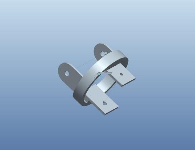
2nd International conference on Advances in Mechanical Engineering (ICAME 2018)            IOP Publishing
IOP Conf. Series: Materials Science and Engineering 402 (2018) 012019 doi:10.1088/1757-899X/402/1/012019
                                               1234567890‘’“”

        To generate a sine wave using PWM pins, will use two pins for positive half cycle and negative half
cycle. Creating a sine wave has its importance particularly with devices like microcontrollers which keeps
running on digital voltages. The sine wave is alluded to as the fundamental of all sort of waveform since the
mix of sine waves can create any required wave. In microcontroller frameworks the simple yield like sine
wave is created with the assistance of digital pulses itself which are produced such that their width is
balanced comparing to the amplitude variations of a sine wave.
        The robot motion should optimize by changing the amplitude, phase and frequency values to get an
optimized sidewinding motion. The experimental results should compare with the simulation results using
MATLAB [14] [15].

                                           Figure 2. Process Diagram

                                                      3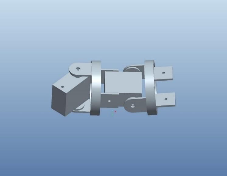
2nd International conference on Advances in Mechanical Engineering (ICAME 2018)            IOP Publishing
IOP Conf. Series: Materials Science and Engineering 402 (2018) 012019 doi:10.1088/1757-899X/402/1/012019
                                               1234567890‘’“”

2.1. Mechanical Specification
                             Table 1. Mechanical specification of snake robot

           SPECIFICATIONS                                     DETAILS
             Number of joints                                     12
             Size of link (mm)                                100x80x80
           Weight of link (Kg)                                   0.168
       Motion Range of joint [deg]                             [-90, +90]
                Actuators                                Dual shaft servo motor
                                                         16Kg.cm Stall Torque
                 Sensors               Ultrasonic Sensor, Temperature Sensor (DHT11)
                   Battery                                   7.4v 4400mah

2.2. Servo Motor
The following cad model is the dual shaft servo motor chosen for snake robot.

                                  Figure 3. CAD model of Servo motor

                                                     4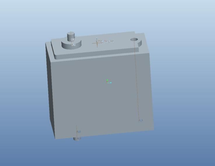
2nd International conference on Advances in Mechanical Engineering (ICAME 2018)            IOP Publishing
IOP Conf. Series: Materials Science and Engineering 402 (2018) 012019 doi:10.1088/1757-899X/402/1/012019
                                               1234567890‘’“”

The dual shaft servo meter has the dimensions 39.88mmx19.81mmx36.32mm. Command signal for this
servo motor is pulse width modification. The gear is made up of metal and its total weight is 59g. It has 2
ball bearings.
        Sine curve equation is given to the servo motor using PWM pins to get the serpentine locomotion
where it’s similar to serpenoid curve.

                                        Figure 4. Serpenoid curve
When V= 6.0, torque and no-load speed is 16kg.cm and 0.16sec/60deg.
When V= 7.4, torque and no-load speed is 18.2kg.cm and 0.14sec/60deg.
Therefore, the speed of the servo motor is decreased when increasing in voltage.
2.3. Module
The figure 4. is the module which two servos will be placed for roll and yaw joint.

                                      Figure 5. 3D model of Module

                                                      5
2nd International conference on Advances in Mechanical Engineering (ICAME 2018) IOP Publishing
IOP Conf. Series: Materials Science and Engineering 402 (2018) 012019 doi:10.1088/1757-899X/402/1/012019
1234567890‘’“”
The figure 5. is the frame where two servos are connected by alternate sides, which one servo is
used for yaw joint and another is used for rolling joint.
2.4. Single Module
The figure 6. is the assembly of the servo motor and frame. Two servos assembly with the frame makes
the yaw and rolling joint.
Each module will have two active joints and this module helps to generate body friction with the
environment.
Figure 6. Assembly of single module
One module consists of two active joints which means two servo motors will be connected in the
module for yaw and rolling motion.
2.5. Snake Robot Assembly
62nd International conference on Advances in Mechanical Engineering (ICAME 2018) IOP Publishing
IOP Conf. Series: Materials Science and Engineering 402 (2018) 012019 doi:10.1088/1757-899X/402/1/012019
1234567890‘’“”
Figure 7. Snake robot assembly using aluminium brackets
3. Control Interface
The control interface is divided into three parts: pc, wireless and snake robot. The pc will analysis and
display the sensor parameters and display of video in real time. The pc software with GUI providing master
control of the robot. The bluetooth module on pc and robot side will make highly secure one to one
communication.
Figure 8. Block diagram of control interface
The snake robot consists of 6 modules which has 12 servo motors, a DHT11 temperature sensor and Arduino
Mega as its microcontroller. All the servo motors are supplied with a 7.4v 4400mah battery to power up and
the control signal is from the Arduino mega controller.
72nd International conference on Advances in Mechanical Engineering (ICAME 2018) IOP Publishing
IOP Conf. Series: Materials Science and Engineering 402 (2018) 012019 doi:10.1088/1757-899X/402/1/012019
1234567890‘’“”
4. Locomotion
4.1 Sidewinding Motion
Sidewinding is a movement utilized by snakes when they are on moving landscape, for example, sand.
This movement is really a blend of the serpentine and rectilinear movements. To accomplish this
movement the robot must be reconfigured. A side section associating one fragment to the C-section of the
following portion is unscrewed and pivoted 90 degrees. This is done along the whole length of the snake.
The odd servos will be situated concerning serpentine movement and even servos will have situated with
respect to rectilinear movement. Sidewinding movement is accomplished by sending a flat cosine wave
down the odd numbered servos and a vertical cosine wave (counterbalance from the level wave by 90
degrees) down the even numbered servos. The outcome is a sideways movement.
Signal modulation changes a sine wave to encode information. The equation representing a sine wave is as
follows,
. cos(2 + ) (1)
Where A is the amplitude, f is the frequency, t is the time and is the phase of the sine wave.
. (90 + ∗ cos ∗ ∗ − ∗
(2)
In the equation (2)., the Arduino command is used in a loop to create the sidewinding motion. Where n is
the quantity of the present segment and takes esteems from 1 to 12, amp decides how wide the wave is (i.e.
how much the "S" shape is bended), freq (along the variable delay Time) decide the speed of the snake,
counter is the loop variable that takes the snake through its serpentine motion and lag is the consistent
precise contrast between segments. The term
/180 is used to change degrees to radian.
5. Experimental Results
A test setup has been built to exhibit the proposed plan of snake robot. The actuator utilized for investigations
is a dual shaft servo motor. Each link has 2DOF movements of roll and pitch which used to ground and lift
the parts. The quantity of links is additionally in charge for curvature of the snake robot locomotion. This
system is motivated by regular snakes that have more number of vertebrae. Every one of the vertebrae is
considered as one link of the snake robot. Extensive quantities of connections are exceptionally hard to
control in view of high degree of freedom and so the modest number of links will produce results on the
fine curvature. In this manner, in this trial we set a snake robot with 12 segments. The changing of the speed
by directing the frequency of the sidewinding locomotion velocity is approved by the experiment.
Table 2. Testing the sidewinding motion with different amplitudes
S.No Amplitude direction Amplitude Frequency Speed
1 Amplitude Horizontal 30 1 0.206km/hr
Amplitude Vertical 30
2 Amplitude Horizontal 35 1 0.258km/hr
Amplitude Vertical 35
3 Amplitude Horizontal 40 1 0.396km/hr
Amplitude Vertical 40
4 Amplitude Horizontal 45 1 0.365km/hr
82nd International conference on Advances in Mechanical Engineering (ICAME 2018) IOP Publishing
IOP Conf. Series: Materials Science and Engineering 402 (2018) 012019 doi:10.1088/1757-899X/402/1/012019
1234567890‘’“”
Amplitude Vertical 45
5 Amplitude Horizontal 50 1 0.312km/hr
Amplitude Vertical 50
From the table 2., it can conclude that the amplitude value = 40cm and frequency =1Hz is optimum value
to get maximum speed for sidewinding motion.
Figure 9. Sidewinding motion of the robot (optimized)
The figure 9. represents the optimized working of the robot for each second (max 9secs). For completion of
one curve the time taken is 2secs and it can be seen in the figure 9. from t=1sec to t=3sec.
6. Conclusion
This paper presented an experimental result to get maximum speed for sidewinding motion to the proposed
design. The sidewinding motion is obtained by placing the servo motor in horizontal and vertical direction
to ground and lift the parts. Experimental results demonstrated the effectiveness of the sidewinding motion.
Future work will investigate the simulation and experimental results for serpentine motion with obstacle
avoidance using ultrasonic sensor.
7. References
[1] Aksel A. Transeth, Remco I. Leine, Christoph Glocker, Kristin Y Pettersen 2008 3-D Snake Robot
Motion: Nonsmooth Modeling, Simulations, and Experiments. IEEE Transactions on Robotics. 24,
361 - 376
92nd International conference on Advances in Mechanical Engineering (ICAME 2018) IOP Publishing
IOP Conf. Series: Materials Science and Engineering 402 (2018) 012019 doi:10.1088/1757-899X/402/1/012019
1234567890‘’“”
[2] Kazuyuki Kon, Motoyasu Tanaka, Kazuo Tanaka 2016 Mixed Integer Programming-Based
Semiautonomous Step Climbing of a Snake Robot Considering Sensing Strategy, IEEE
Transactions on Control Systems Technology. 24, 252 - 264
[3] Motoyasu Tanaka, Kazuo Tanaka 2017 Shape Control of a Snake Robot with Joint Limit and Self-
Collision Avoidance, IEEE Transactions on Control Systems Technology. 25, 1441 - 1448
[4] Pål Liljeback, Kristin Y. Pettersen, Øyvind Stavdahl, Jan Tommy Gravdahl, 2012 Snake Robot
Locomotion in Environments With Obstacles, IEEE/ASME Transactions on Mechatronics. 17, 1158
- 1169
[5] Pål Liljeback, Kristin Y. Pettersen, Øyvind Stavdahl, Jan Tommy Gravdahl, 2010 Hybrid Modelling
and Control of Obstacle-Aided Snake Robot Locomotion, IEEE Transactions on Robotics. 26, 781
- 799
[6] Pål Liljeback, Kristin Y. Pettersen, Øyvind Stavdahl, Jan Tommy Gravdahl, 2011 Experimental
Investigation of Obstacle-Aided Locomotion with a Snake Robot, IEEE Transactions on Robotics
27, 792 - 800
[7] Ryo Ariizumi, Fumitoshi Matsuno 2017 Dynamic Analysis of Three Snake Robot Gaits, IEEE
TRANSACTIONS ON ROBOTICS. 33, 1075 - 1087
[8] Motoyasu Tanaka, Kazuyuki Kon, Kazuo Tanaka 2015 Range-Sensor-Based Semiautonomous
Whole-Body Collision Avoidance of a Snake Robot, IEEE Transactions on Control Systems
Technology. 23, 1927 - 1934
[9] Peipei Shi, Qianjun Shao, Dongtai Liang 2016 Design and improved serpentine curve locomotion
control of a planar modular snake robot, IEEE International Conference on Information and
Automation (ICIA). 1398 - 1402
[10] Motoyasu Tanaka, Kazuo Tanaka 2016 Singularity Analysis of a Snake Robot and an Articulated
Mobile Robot with Unconstrained Links, IEEE Transactions on Control Systems Technology. 24,
2070 - 2081
[11] Chao Wang, Hong-bin Deng, Fei Xia, Yang Li 2016 Study on climbing locomotion mechanism of
snake robot with universal unit, 8th International Conference on Modelling, Identification and
Control. 460 - 465
[12] Md. Masum Billah, Md. Raisuddin Khan, Amir Akramin Shafie 2015 Autonomous flexible snake
robot for 3D motion, IEEE International Symposium on Robotics and Intelligent Sensors (IRIS).
105 - 110
[13] Motoyasu Tanaka, Kazuo Tanaka 2015 Control of a Snake Robot for Ascending and Descending
Steps, IEEE Transactions on Robotics. 31, 511 - 520
[14] Aksel Andreas Transeth, Remco I. Leine, Christoph Glocker, Kristin Ytterstad Pettersen, PÅl
LiljebÄck 2008 Snake Robot Obstacle-Aided Locomotion: Modeling, Simulations, and
Experiments, IEEE Transactions on Robotics. 24, 88 - 104
[15] Dinal Herath H M J, Jayananda M K 2016 Comparison of serial and parallel snake robots for lateral
undulation motion using Gazebo, IEEE International Conference on Information and Automation
for Sustainability (ICIAfS). 1 - 6
10You can also read