Tethered Detachable Hook for the Spiderman Locomotion (Design of the Hook and its Launching Winch)
←
→
Page content transcription
If your browser does not render page correctly, please read the page content below
Tethered Detachable Hook for the Spiderman
Locomotion
(Design of the Hook and its Launching Winch)

Nobukazu ASANO, Hideichi NAKAMOTO, Tetsuo HAGIWARA, Shigeo
HIROSE

Abstract This paper introduces a new concept of ”tethered detachable hook (TDH)”
and its launching winch. TDH system is the device which will be mounted on a mo-
bile robot and enhances its traversability over extremely hostile terrain by launching
detachable hook to nearby objects, producing large traction force by the tether and
detaching/recovering the hook to the launcher again. In this paper the authors first of
all introduce several prototype models of the TDH. We then discuss the design of lat-
est model which features pneumatic detaching mechanism, the pneumatic launcher
and the reel mechanism having three motion states; active rotation, free rotation and
braking. Finally, the result of several experiments of constructed TDH model will
be explained.

1 Introduction

Many types of mobile robots have been developed so far to move on off-the-road
terrains, such as modified wheel, track, legs, and snake-like configuration. Even
jumping can be considered as one of the means for high mobility [1]. However,
if long and steep slope or ditch much wider than the size of the robots is on the
way, terrain adaptability of these conventional methods is not enough. In this paper,
we propose a new type of locomotion method which assists the mobility of these
mobile robots. It consists of ”tethered detachable hook” and its launcher and winch
system, which assists the mobile robot as shown in Fig.1(a). Here the mobile robot

Nobukazu ASANO, Shigeo HIROSE
Tokyo Institute of Technology, 2-12-1, Ookayama, Meguro-ku, Tokyo, 152-8552, Japan, e-mail:
nasano@robotics.mes.titech.ac.jp, hirose@mes.titech.ac.jp
Hideichi NAKAMOTO
Toshiba Corporation, 1, KomukaiToshiba-cho, Saiwai-ku, Kawasaki-shi, 212-8582, Japan
Tetsuo HAGIWARA
KinderHeim Corporation, 335, kaminakazato-cho, Isogo-ku, Yokohama-shi, 235-0045, Japan

                                                                                         1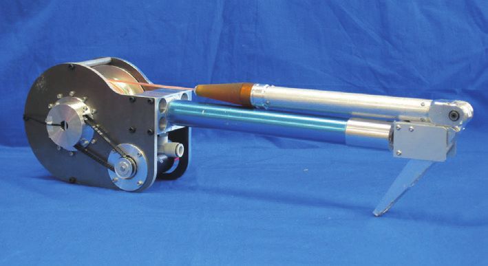
2            Nobukazu ASANO, Hideichi NAKAMOTO, Tetsuo HAGIWARA, Shigeo HIROSE

is going to climb the steep slope and the ”tethered detachable hook” is launched to
the branch of a tree. When the hook is connected to the branch, the winch winds the
tether and produces large traction force to assist the robot to go over the steep slope.
After the motion is over, the hook is detached from the branch by changing the shape
of the hook to smooth and linear shape, rewinding the winch, and finally restoring
the hook in the launcher again to prepare for the next launching task. If the mobile
robot has more than two tethered detachable hooks and their launcher-winch system,
it can even lift itself from the ground and move from branch to branch as shown in
Fig.1(b). This is like the motion of long-armed ape in forest or the spiderman flying
from building to building.
    Until now several tethered robots were already proposed, such as TITAN VII [2]
or DANTE II [3]. They are supported by tethers which are anchored beforehand
at the top of the slopes. Cliffbot [4] is supported by an anchor robot which stays
at the top of the cliff and connected by the tether. Casting manipulator [5] has the
tether with a gripper at the end and casted to catch an object. Although the objective
of this casting manipulator was for the manipulation of a remotely located object,
the concept can easily be extended to the supporting system for mobile robot. The
automated tether management system [6] is most closely related to our concept. It
used a tether with a gripper which can be remotely operated to lock or detach it
and help the flying motion of a space robot. But as it is designed for the activity in
micro-gravity environment, the system can not directly apply for the application of
field robotics which we are targeting in this paper.
    This paper is organized as follows. Section 2 describes the design of former mod-
els of TDH. Section 3 presents design of the latest model of TDH and its launching
winch. Section 4 reports experimental results of the constructed TDH and its launch-
ing winch. Section 5 concludes the results and proposes future works.

2 Former Models of Tethered Detachable Hook

2.1 Model I

As the first model of the ”tethered detachable hook”, the authors developed the
Model I as shown in Fig.2(a). Although we call it as ”tethered detachable hook”, we

          Cast              Climb             Detach
            (a) Slope climbing by using TDH            (b) Ditch crossing by using a pair of TDHs

Fig. 1 Concept of tethered locomotion by using tethered detachable hook(TDH)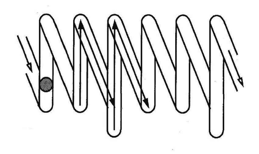
Tethered Detachable Hook for the Spiderman Locomotion                                                              3

did not selected the hook but gripper. As shown in Fig.2(a) and (b), the gripper is
designed to grip an object when the tip end of the rod contact the object and hold
its gripping state by the ratchet mechanism. Ability to hold the object tight was the
main reason why we selected gripper configuration for this first model. Release of
the gripping motion is designed to be done by a mechanical memory system. The
mechanical memory system is already used in the ballpoint pen with different colors.
It consists of a cylindrical cam with zigzag grooves (Fig.2(c)) in which the pin fixed
to the external cylinder is inserted. When the tension of the tether connected to the
cylindrical cam changes and drives the cam to make reciprocating motion, the cam
is driven by the pin and starts to rotate in one direction. In the three zigzag grooves,
one of the grooves is made longer, so the ratchet release rod is inserted in the ratchet
trigger to release the ratchet and open the finger every three times of the pulling
motion of the tether.
    For this Model I we also made simple launcher and made the experiment to cast
it to the branch. Once it is gripped the branch, it showed strong connection and
release motion was also very smooth. But the problem of this first model was its
difficulty of aiming at the target object (branch). The gripper should be aimed at the
object precisely in position and also in orientation; otherwise the gripper could not
hold the object successfully. This is the big problem if we hope to make automatic
launching system. Another problem of this first model was the shape of the gripper
in open state. It is not streamlined and there is always the danger to be stacked in
narrow gap.

2.2 Model II

To solve the difficulty of precise aiming of the target, we selected hook for the
following models. The Model II of the tethered detachable hook is shown in Fig.3.
As shown in Fig.3, the Model II also adopted the mechanical memory system, and it
could be released by pulling the tether for few times. Repeated traction of the tether

                          Trigger release spring                                                 Pin

               Rachet release rod                                                    1

            Ratchet trigger                             Pin
         Fingers                            Cylindrical groove cam

                                                                                     2
                                       Ratchet

                               Fingers release spring

                                                                                     3     Release points

                      (a) Mechanism                                  (b) Gripping motion   (c) Zigzag cam motion

Fig. 2 Mechanism of the TDH model I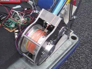
4                     Nobukazu ASANO, Hideichi NAKAMOTO, Tetsuo HAGIWARA, Shigeo HIROSE

rotate the cylindrical cam and it drives the lock lever, and release the stopper to open
the claws.
   The Model II has four claws attached radially at the end of the hook so that the
hook can be anchored to the target object much easier than the gripper. It can be
hooked the target object only by throwing it over the target. The Model II was much
easier to connect to the target objects than former model, however it still remained
several problems. One of them is its weight. As there are four claws, it is heavy and
powerful launcher is needed. The second problem is the shape of the hook in release
state. Although the shape is more streamlined than that of Model I, the shape is still
in wedge like and there remained the possibility to be stack in narrow gap while it is
recovering to the launcher. The third problem is the possibility of mal-operation of
the mechanical memory system, for the tether will always be affected by accidental
pulling and releasing motion and it may be released by chance.

2.3 Model III

To solve the problems mentioned above, we developed Model III. The model III has
three important modifications as follows;
1. reduce the number of claws from four to one
2. change the shape of the hook as a simple rod in the release state
3. introduce active detaching mechanism
    Modification 1 is done to reduce the weight of the hook. We selected four claws
configuration for the Model II to secure reliable anchor action in any posture of
the hook. However, we found that even one claw hook can exhibit similar action
only by adding enough length and weight to the claw. Effect of this configuration
is observed in the experiment of Fig.10. In this experiment, when the hook pulled
slowly over a branch (in this case a pipe), the hook will rotate around its stem and
let the claw lower on the branch as the claw is heavy, and thus the claw grips the
branch.
    Modification 2 is done to minimize the stack action while the hook is in retract-
ing state. As shown in Fig.4, the hook is designed to change from L-shaped state
to linear-shaped state. Difficulty of realizing this shape was in the joint design of

Tether   Pin   Cylindrical Intermittent    Lock lever Set ring Claw Stopper
               cam         swash plate cam

                                                                        Detach

                                                                         Reset

Fig. 3 Mechanism of the TDH model II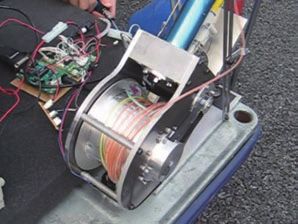
Tethered Detachable Hook for the Spiderman Locomotion 5
the claw. As large torque is applied at the joint to support large traction force of
the tether, the joint mechanism has to produce large torque and the joint tends to be
bulky and heavy. To solve this problem, we introduced tether supported joint mech-
anism. In this mechanism, the end of the tether is connected to the claw and joint
torque is directly supported by the traction of tether as shown in Fig.4. The tether is
designed to go out of the joint to produce large torque in this hooked state. In the
linear-shaped state, to the contrary, the tether retracts inside the joint and the joint is
made slender.
Modification 3 is done to eliminate the expected malfunction of the release mo-
tion depending upon the accidental pulling action of the tether. The mechanical
memory system was ideal because normal rope can be used as the tether and lock-
and-release mechanism of the hook in Model II, or gripper in Model I could be
made comparatively simple. To make comparative system with high reliability, we
considered electric and pneumatic types of trigger driving mechanisms.
Design of the electric detachable mechanism is shown in Fig.5. A stopper is
connected to the tether and the stopper is locked by a trigger that is fixed by the
rod (Phase 1). In this state, the hook holds L shaped configuration and act as an
anchor. Release motion of the hook is done by rotating the screw by the small motor
and slides the rod fixing the rotation of the trigger. This motion frees the stopper
and the tether automatically slides to open the claw in a release state by the spring
attached around the joint (Phase 2). Required electric current is very small and it
can be supplied by small diameter electric wire inside the tether. As the tether has
to support large traction force, we used a Kevlar fiber-reinforced wire together
with the fine electric wires. The authors have already used it as the ”Hyper Tether”
system [7] and Anchor climber [8].
Stopper Trigger Wire
Detach
Reset
Fig. 4 Basic structure of the TDH model III
Trigger Rod Nut Screw Motor
1 2
Stopper Wire
Fig. 5 Electric detach type of the TDH model III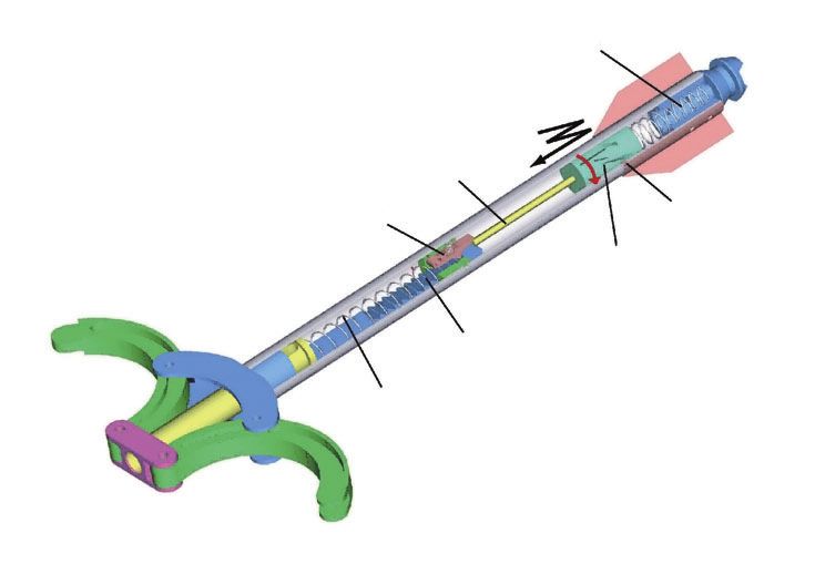
6              Nobukazu ASANO, Hideichi NAKAMOTO, Tetsuo HAGIWARA, Shigeo HIROSE

    A pneumatic detachable mechanism is shown in Fig.6. The tether consists of air
tube and wire, and the end of the tube is connected to a small air bag which is located
inside a stopper. The stopper can slide inside a pipe fixed to the hook and the stopper
is locked by the trigger as shown in Fig.6 (Phase 1). The wire inside the air tube is
connected to the stopper and the end of the wire is connected to the claw. Detaching
motion of the hook can be done by supplying pressurized air in the air tube and
expand the airbag. Expanded airbag pushes out the projection point of the bag and
drive the trigger out of the hole and release the stopper (Phase 2). It enables the
stopper and the wire connected to slide freely and open the claw. Although the gap
between air tube and wire (polyethilene line) is small, we found that the pressurized
air could easily be transmitted along the air tube longer than 10[m] with ease.

Table 1 Specifications of the TDH model II & III
Type                             Mass               Total length   Length of claw
Model II                         840 [g]            435 [mm]       85 [mm]
Model III (Electric)             395 [g]            325 [mm]       150 [mm]
Model III (Pneumatic)            390 [g]            345 [mm]       150 [mm]

   We successfully made both types of detachable mechanisms and verified their
motions. Specifications of these types are shown in Table 1 with those of Model II.
Between these types, we selected the pneumatic type, because tether of the pneu-
matic type can be lighter and driving mechanism of the hook can be lighter and
rugged enough to be protected against the shock.

3 Design of Launching Winch for the Tethered Detachable Hook

A casting device developed for TDH Model III is shown in Fig.7. It consists of a
launcher for the hook and a winch to wind the tether.

    1      Stopper   Spring      Trigger       2

Air tube    Fiber       Airbag   Wire
                                              Air
Fig. 6 Pneumatic detach type of the TDH model III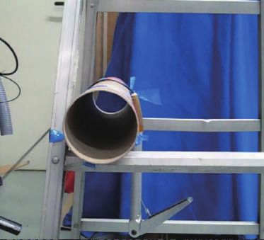
Tethered Detachable Hook for the Spiderman Locomotion                                                              7

    First we describe a launcher. Among the spring type and pneumatic cylinder
type, we found that the pneumatic one is better because it can generate powerful
and high speed launching motion with lightweight mechanism. We already adopted
pneumatic hook detachable system and selection of the pneumatic system for the
launcher will have other effect to make the total system simple. One of the most
important parts of the launching system is in its trigger mechanism, and designed
mechanism is shown in Fig.8. At first, a piston is locked by a ball type trigger, and
is pressed by high-pressured air from ”Port A” as shown in Fig.8(a). At this time,
high-pressured air from ”Port B”, that is for the control rod, is also supplied. Launch
motion can be done by decompress the air for ”Port B” and drive the control rod out
of the balls and let the air pressure from ”Port A” drives the piston go right direction
and launch the hook(Fig.8(b)). Compared with the trigger mechanism using normal
valve, introduced mechanism can makes the trigger motion smoothly and as the
pressurized air gives pressure to the hook from the beginning, it can increase the
initial speed of the hook and enable it to cast in longer distance.
    Next we explain a winch for the TDH. It is designed to have three modes; drive
mode, free mode and brake mode.
    The ”drive mode” is used when it is used as winch, and large traction force should
be generated to support a robot. The ”free mode” is used when the hook is going
to be launched. As the spool have to rotate in high speed, the actuator to produce
large traction force in drive mode should be mechanically disconnected. The ”brake
mode” is needed for two reasons, one of them is to support the suspended robot
without energy loss and the other is to adjust the rotational speed of the winch
when it is in ”free mode” and launching the hook. As the hook is launched by

                                                                              Reel                  Casting hook

Fig. 7 Overview of a launch-
ing winch with pneumatic
TDH model III                                                                                  Launcher

Spring   Trigger housing    Control rod   Balls   Piston   Piston rod

 Port B :                                                               Port B :
 ON                                                                     OFF

 Air holes                  Port A : ON                                               Port A : ON

                           (a) Standby                                               (b) Launch
Fig. 8 Pneumatic trigger mechanism of the launcher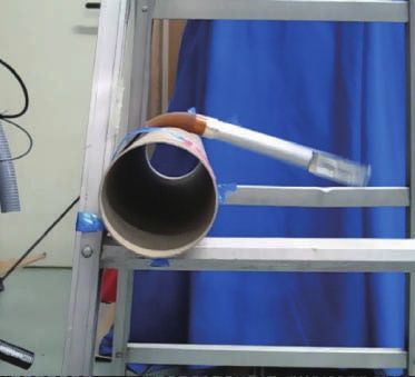
8             Nobukazu ASANO, Hideichi NAKAMOTO, Tetsuo HAGIWARA, Shigeo HIROSE

pneumatic pressure, winch in free mode tends to keep rotating while the hook is
flying. However the speed of the hook decelerates while flying and the tether tends
to excessively goes out of the reel and entangle around the reel. This phenomenon
is called as ”backrush” among anglers for their fishing reel motion. To prevent the
backrush we need proper braking of the winch in the free mode.
    To switch these 3 modes, we adopted a multi-plate clutch mechanism which is
installed inside the spool as shown in Fig.9. Multiple input and output clutch plates
are piled up to increase the braking torque. Maximum torque of this clutch mecha-
nism Tc can be estimated as follows;

                                    Tc = N p µ Fp re                                (1)

where, Np is the number of friction surfaces between clutch plates, µ is the coeffi-
cient of static friction, Fp is a pushing force for clutch plates generated by the motor
thrusting force and re is an effective radius of friction surfaces.
   As the winch rotate infinitely and pressurize air have to be supplied to the air tube
to connect the hook, a rotary pneumatic joint is introduced. Air is supplied from a
joint in right section of the figure, and it pass through holes on a hollow shaft. Two
movable O-rings are installed to prevent the leak of the air.

            Frame
                                                                   Spool

    Harmonic gear                                                  Encoder
    Circular spline
        Flex spline                                                Clutch
                                                                   pusher
    Wave generator
                                                                   Pneumatic
                                                                   rotary joint
                                                                   Slide
                                                                   screw
     Clutch-control
     motor                                                         Spool-drive
                                                                   motor
      Clutch plates

       Timing belt

Fig. 9 Mechanism of the winch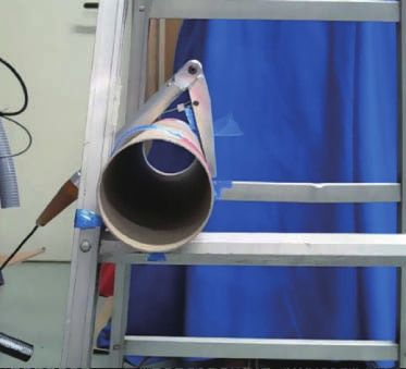
Tethered Detachable Hook for the Spiderman Locomotion 9
4 Experiment
The authors confirmed motion performance of tethered detachable hook of Model
III. Basic motion to hook the object was examined as shown in Fig.10. As is dis-
cussed before, the claw was automatically lowered and gripped the branch when the
hook was pulled and located above the object. From this experiment, we confirmed
the validity of introducing the one claw configuration for the TDH.
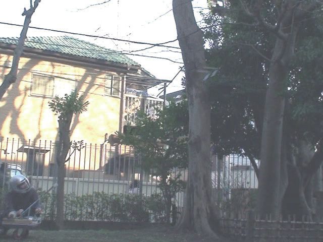
Next, the authors made a simple experiment of casting the Model III TDH to the
real branch of the tree as shown in Fig.11. From this experiment, the anchoring func-
tion of the hook and its detaching motion was successfully demonstrated. Besides,
smooth collection was achieved because of its straight shape after the detaching
motion.
With the casting device mentioned above, the authors also made the experiments
to verify the effectiveness of the prevention of ”backrush” by the braking. Fig.12(a)
shows the comparison of the tether on the after launching the hook. Left is the result
without braking and right is the result with proper braking. From the comparison
of these results, we know the importance of the braking of the winch in free mode.
Fig.12(b) shows measurement results of outer circumferential velocity of the winch.
They were measured by an encoder connected to the winch. From this figure too, we
can know that proper braking enable to increase the launching speed. In Fig.12(b)
Fig. 10 Sequential motion to
show the self adjustment of
the claw direction to the target
branch 1 2 3
3.5[m]
2.5[m]
Object
to anchor 2. Anchor
Fig. 11 Real launching ex-
periment of the TDH model
III to the branch of a tree 1. Cast 3. Detach
10 10
Outer circumferential velocity
9 9
8 Without brake 8 With brake
7 7
6 6
of the winch [m/s]
5 5
4 4
3 3
2 2
1 1
0 0
0 0.2 0.4 0.6 0.8 1 1.2 1.4 1.6 1.8 2
Without brake With brake 0 0.2 0.4 0.6 0.8 1 1.2
Time [sec]
1.4 1.6 1.8 22
Time [sec]
(a) Comparison of the tether with and without braking control (b) Measurement results of outer circumferential velocity of the winch
Fig. 12 Comparison experiment with and without braking control10 Nobukazu ASANO, Hideichi NAKAMOTO, Tetsuo HAGIWARA, Shigeo HIROSE
we can observe the speed change of the reel at the time near the 1.2[sec]. It is caused
by the falls of the hook on the ground.
5 Conclusions and Future Works
This paper introduces a new concept of ”tethered detachable hook (TDH)” and its
launching winch for use as the locomotion assisting device for mobile robots. This
paper firstly discusses about several prototype models of the TDH and elaborate lat-
est model, such as pneumatic lock and release mechanism of the hook, pneumatic
launcher and the reel mechanism which exhibits three motion states; active rota-
tion, free rotation, and braking of the rotation. Performance of developed TDH and
its launching winch are successfully demonstrated by the constructed mechanical
model. Study of the proposing tethered detachable hook (TDH) is still at the
starting point, and there remained many interesting research subjects to be studied
on the hook, launcher, and winch mechanisms and their control. We are hoping to
study further on these points and realize the mobile robots having TDH and move
around mountainous area or disaster site by successively casting the tethers around
the environment just like Spiderman does among buildings in near future.
References
1. T.Tanaka, S.Hirose, Development of leg-wheel hybrid quadruped ”AirHopper” design of
powerful light-weight leg with wheel, IROS2008, pp.3890-3895, 2008.
2. R.Hodoshima, T.Doi, Y.Fukuda, S.Hirose, T.Okamoto, J.Mori, TITAN VII: quadruped walk-
ing and manipulating robot on a steepslope, ICRA1997, pp.494-500, 1997.
3. M.Krishna, J.Bares, E.Mutschler, Tethering System Design for Dante II, ICRA 1997,
pp.1100-1105, 1997.
4. JPL Robotics: http://www-robotics.jpl.nasa.gov/
5. H.Arisumi, K.Komoriya, Catching Motion of Casting Manipulation, IROS 2000, pp.2351-
2357, 2000.
6. M.A.Minor, C.R.Hirschi, R.O.Ambrose, An Automated Tether Management System for Mi-
crogravity Extravehicular Activities, ICRA 2002, pp.2289-2295, 2002.
7. E.F.Fukushima, N.Kitamura, S.Hirose, A New Flexible Component for Field Robotics System,
ICRA 2000, pp.2583-2588, 2000.
8. S.Kitai, K.Tsuru, S.Hirose, The proposal of Swarm Type Wall Climbing Robot System ”An-
chor Climber”: The Design and Examination of Adhering mobile unit, IROS 2005, pp.475-
480, 2005.You can also read