Dynamic Response Analysis of Stiffened Triceratops under Regular Waves - irjet
←
→
Page content transcription
If your browser does not render page correctly, please read the page content below
International Research Journal of Engineering and Technology (IRJET) e-ISSN: 2395-0056
Volume: 05 Issue: 05 | May-2018 www.irjet.net p-ISSN: 2395-0072
Dynamic Response Analysis of Stiffened Triceratops under Regular Waves
Harija K S1, Dr. Jayalekshmi R2
1PG Student, Department of Civil Engineering, NSS College of Engineering, Palakkad
2Professor, Department of Civil Engineering, NSS College of Engineering, Palakkad
---------------------------------------------------------------------***---------------------------------------------------------------------
Abstract - Offshore triceratops is fairly an emerging concept this independent motion essentially in terms of rotation, will
with respect to the structural form that has been tried for not be transferred to the hull because of the ball joint.
ultra-deep waters. It consists of a deck, buoyant leg structures Similarly, when the hull starts activating or rotating because
(BLS), ball joints and the platform is position-restrained by of the aerodynamic force, the wind action is not transferred
tethers. Ball joints connects deck to the positively buoyant BLS to the BLS. Ball joint makes the structure different from
units. Ball joint restrains the transfer of rotations between the other platforms. Restraining system can be either a
deck and the BLS as well. Introduction of ball joints between restraining leg or tether. If depth of water is less than 1500
the deck and buoyant leg structure (BLS) makes triceratops m, restraining legs will be employed and if it is greater than
different from other offshore structures. In case of a stiffened 1500 m, tethers act as a restoring system. The restoring
triceratops, each buoyant leg unit is stiffened using a set of system will be under high pretension. Excess buoyancy
stiffeners joining the three columns and central moon-pool. ensures high initial pre-tension of tethers. Foundation
Stiffeners are added to make the BLS units monolithic and in system can be a suction pile, multiple driven piles or a
that way reducing the effect of the encountered wave loads. gravity base structure.
This study aims to find out the dynamic behavior of the
stiffened triceratops under regular and random waves. Buoyant legs are designed as stiffened cylinders since they
have to resist both axial stress and bending moment caused
Key Words: Triceratops, Buoyant Leg Structure, Central by lateral forces. Stiffeners are welded to the shell, this
Moon Pool System, Stiffeners. enhances their lateral resistance. In addition to ring
stiffeners, longitudinal stiffeners called as stringer stiffeners
1. INTRODUCTION are also provided at equal spacing, both externally and
internally. The operational advantages of the structural
Since hydrocarbons have started depleting in shallow water, configuration include its reduced deck response and good re-
oil exploration is moving towards greater water depths. centering capability.
Offshore structure should be enabled to counteract the
lateral force acting on it by its geometric arrangement. There
arises the need for new generation offshore platforms to be
developed which will be capable of balancing the load acting
on it. One among the developing platforms is triceratops. A
lot many researchers have studied the response behavior of
several innovative structural forms. The concept of Buoyant
Leg Structure(BLS) was introduced by Robert W. Copple et
al. (1995). The studies have shown that it suits well in deep
water and was cost effective. Charles N. White et al. (2005)
introduced the concept of triceratops platform. It has
evolved its form from BLS, TLP and SPAR as well.
Triceratops is a new generation platform proposed to serve
deep water applications. Its main components are deck
structure, buoyant leg structures (BLS), ball joints that
connect buoyant legs with deck, tethers and a foundation
system. Deck structure is equipped to serve topside facilities
like providing space for crew quarters and for other
production facilities. BLS is a positively buoyant system. The
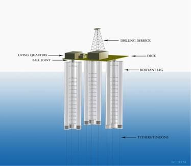
BLS unit resembles a SPAR due to its deep draft, while the Fig 1: Conceptual view of a Stiffened Triceratops
restraining system makes it act more like a TLP. Deck is
Ball joint carries the entire weight of the deck and holds the
partly isolated from the buoyant legs by ball joints. Ball
equally spaced buoyant leg structures (BLS). Faults in this
joints are special components that transfer displacements
element as a result of corrosion, fatigue, fabrication errors,
from BLS to deck structure and restricts the transfer of
etc. can probably lead to the breakdown of this structure.
rotations. Comfortable working environment is guaranteed
Any defect on each of the ball joint will impose more load on
to the people on board by restraining transfer of rotation to
other bearing ball joints on the structure that can eventually
the deck. Since the BLS are not interconnected to each other,
cause the entire structure to collapse.
each one of them have the freedom to move independently,
© 2018, IRJET | Impact Factor value: 6.171 | ISO 9001:2008 Certified Journal | Page 1997International Research Journal of Engineering and Technology (IRJET) e-ISSN: 2395-0056
Volume: 05 Issue: 05 | May-2018 www.irjet.net p-ISSN: 2395-0072
1.2 Advantages Table 2: Geometric properties of triceratops
The structural form of offshore triceratops is less complex Description Quantity
than that of TLPs and Spar. It only requires simpler station Water depth 896 m
maintenance systems. The installation and decommissioning Density of steel 7850 kg/m3
of the platform contribute to a significant reduction in
Density of sea water 1025 kg/m3
spending, making it more affordable. The risers are
Total length of leg 155 m
positioned in a protected environment making them laterally
supported. This contributes to additional safety. Draft 125 m
Freeboard 30 m
Common types of offshore deep-water structures have rigid c/c distance b/w legs 70 m
connections. This leads to the production of more stress on Outer diameter of cylinder 9.5 m
the members, when they are subjected to environmental
Thickness of cylinder 40 mm
loads. Triceratops reduces the severity of environmental
Outer diameter of moonpool 5m
loads encountered under its new structural form and design.
The advantages of triceratops are as follows: Thickness of moonpool 25 mm
Vertical COG of BLS 44.74 m
(i) Simplicity of the structure, simpler station keeping Metacentric height 16.668 m
system and simpler restraining system Length of tether 771 m
(ii) Easy to install and decommission; Stiffness of tether 203 MN/m
(iii) Reusable and re-locatable;
4. NUMERICAL MODELING AND ANALYSIS UNDER
(iv) Forces acting on the platform is reduced due to the REGULAR WAVES
reduction in the exposed fraction of the structure
The numerical analysis was carried out using the finite
(v) Risers are protected from lateral forces since they are element software ANSYS AQWA. Deck is modelled and its
situated inside the moon pool. weight and payload is assigned at the mass center of
deck. BLS units are modelled as line elements in ANSYS
(vi)Reduced deck response offer better working
AQWA, as they qualify for the Morison region (πD/ℓ< 0.5).
environment to the workers
Mass center of each group of legs is assigned with buoyant
leg mass and ballast loads. TUBE elements are used to model
2. STIFFENED TRICERATOPS
the buoyant legs. BLS unit is connected to the deck by means
A finite number of stiffeners are used to connect three of ball joints. Ball joints are modelled to transfer all
columns of single BLS unit to the central moon-pool. This translations and no rotation to the deck. Tether which
makes the structure a stiffened triceratops. These stiffeners extends from keel of each buoyant leg to the seafloor is
make the BLS units monolithic and henceforth decrease the modelled as cable elements with suitable axial stiffness and
effect of the wave loads on the structure. the initial tension is imparted to the cable by stretching it.
3. PRELIMINARY DESIGN Equation of motion for free oscillation studies is as
follows:
The triceratops is proposed at a water depth of 896 m at
+ + = [Ref 3]
Mississippi Canyon, Gulf of Mexico. Configuration is chosen
similar to an existing TLP at the same place. Geometric where [M] is the mass matrix, [Ma] added mass matrix, [C]
details and structural properties are given in the table 1 and
damping matrix, [K] stiffness matrix of the platform,
2. The triangular deck supports the same payload carried by
the MARS TLP. Single BLS unit consist of three cylinders and displacement, velocity and acceleration of the structure.
a central moon pool. These three cylinders are connected to Mass matrix is given by,
the moon pool with the help of stiffeners.
Table 1: Mass properties of triceratops
Description Quantity
Payload 7200 ton
Ball joint 1013 ton
Leg weight 15633 ton
Ballast weight 15738 ton
Pretension 6248 ton
Total displacement 45832 ton
© 2018, IRJET | Impact Factor value: 6.171 | ISO 9001:2008 Certified Journal | Page 1998International Research Journal of Engineering and Technology (IRJET) e-ISSN: 2395-0056
Volume: 05 Issue: 05 | May-2018 www.irjet.net p-ISSN: 2395-0072
Stiffness matrix is given by, regular waves, the amplitude of structural response is
generally normalized with reference to the amplitude of
wave. For linear systems these normalized responses are
invariant to the wave amplitude at a frequency and these are
referred to the response amplitude operator (RAO).
Response Amplitude Operator (RAO) is plotted for the
comparison of response in various degrees of freedom. For a
wave height of 8 m, the wave period chosen is 7 s to 17 s.
Time history response for a time period of 14 s is shown in
fig 3, 4 and 5
The coefficients, kij, of the stiffness matrix of the triceratops
are derived as the reaction in the degree of freedom i due to
unit displacement in the degree of freedom j, keeping all
other degrees of freedom restrained.
Numerical analysis is performed on the model of triceratops
by solving equation of motion under lateral loads as given
below:
+ + =
where {f(t)} is the force vector
To estimate the wave force exerted by waves added mass
and drag coefficient of 1.05 and .75 are assigned
respectively. The wave force is calculated using Morison Fig 2: Direction of wave.
equation:
where is the drag coefficient, is the inertia coefficient,
D is the characteristic drag diameter, is the fluid velocity
in the transverse direction, are the structural velocity
and acceleration respectively in the transverse direction of
BLS, A is the cross-sectional area, is the mass density of
the fluid and is the instantaneous relative velocity
in the considered direction.
Regular waves are simulated in ANSYS AQWA software.
Time history analyses are performed under unidirectional
regular waves for different wave heights and for different
Fig 3: Surge Response of BLS and deck
wave heading angles (0, 120 and 180°) by solving the
equation of motion at each time using the numerical
integration scheme. Nonlinear analysis is carried out in time
domain under regular waves. Airy's wave theory is used for
evaluating the water particle kinematics for the assessment
of hydrodynamic forces on buoyant legs.
5. RESULTS AND DISCUSSIONS
The triceratops has been analyzed for three different wave
heights (8 m, 12m,15m) to find out the variation of response
with wave height. Fig 2 shows the wave heading towards the
triceratops when the wave heading angle is 0°. Triceratops
has also been analyzed for regular wave loading by varying
the wave heading angles (0°, 120° and 180°). In the case of Fig 4: Pitch Response of BLS and deck
© 2018, IRJET | Impact Factor value: 6.171 | ISO 9001:2008 Certified Journal | Page 1999International Research Journal of Engineering and Technology (IRJET) e-ISSN: 2395-0056
Volume: 05 Issue: 05 | May-2018 www.irjet.net p-ISSN: 2395-0072
From fig 6, RAO in surge degree shows that the deck
response is slightly less than the bls response. Fig 7 shows
the heave RAO of the bls unit and the deck. The deck
response seems to be slightly more than the bls response
after 10 s. The rotations of the deck can also induce heave
forces (contribution of k36, k37 and k38 ) Pitch RAO of the
deck and bls is shown in fig 8. From the RAO it is clear that
the deck response is much lesser than the bls response. This
is mainly due to the presence of ball joint. This makes it
clear that the ball joint is effective in restraining rotations to
the deck.
Fig 5: Heave Response of BLS and deck
Time history response show that the deck response in all
active degrees of freedom is reduced with respect to the BLS.
In case of pitch the motion of deck is almost negligible.
RAO of deck and that of a single bls is plotted in surge, heave
and pitch degrees of freedom for different wave height.
Fig 9: Surge RAO for 12 m wave
Fig 6: Surge RAO for 8 m wave
Fig 10: Heave RAO for 12 m wave
Fig 7: Heave RAO for 8 m wave
Fig 11: Pitch RAO for 12 m wave
RAO for 12 m wave height is shown in fig 9, 10 and 11. The
pattern followed is almost same. But the response has
increased.
Fig 8: Pitch RAO for 8m wave
© 2018, IRJET | Impact Factor value: 6.171 | ISO 9001:2008 Certified Journal | Page 2000International Research Journal of Engineering and Technology (IRJET) e-ISSN: 2395-0056
Volume: 05 Issue: 05 | May-2018 www.irjet.net p-ISSN: 2395-0072
Fig 12: Surge RAO for 15 m wave
Fig 16: Heave RAO of fore BLS under various wave heading
angle
Fig 13: Heave RAO for 15 m wave
Fig 17: Pitch RAO of fore BLS under various wave heading
angle
Fig 15, 16 and 17 shows the surge, heave and pitch RAOs
respectively of fore BLS under 0°, 120° and 180° wave
Fig 14: Pitch RAO for 15 m wave
heading angle. From the RAO it is observed that the
RAOs in fig 12, 13 and 14 shows the response at 15 m wave response for 0° and 180° wave heading angle remains almost
height for time period varying from 9 to 18 s. the same but the response for 120° heading angle is reduced.
This may be because of the reduction in wave forces at the
By comparing the response of triceratops with varying wave point of application. This reduction in wave force can be
height, it is seen that the response of deck and BLS increases accounted due to the angle of inclination of wave force .
with increase in wave height.
4. SUMMARY AND CONCLUSIONS
The response of the fore bls is found out for various wave
heading angle (0°, 120° and 180°) and plotted as RAOs. Structures in deep and ultra-deep water will be subjected to
loads of higher intensities and they should be designed to
withstand the loads acting on it. Offshore triceratops is an
emerging platform which has been proved suitable for deep
waters. A triceratops has been designed for a water depth of
896 m. the selected site is located at Mississippi Canyon, Gulf
of Mexico. Numerical studies have been conducted on
triceratops under unidirectional regular waves. The
structure is stiff in heave degrees of freedom. Thus makes it
more adaptable to deep waters. Studies done by varying the
wave heights have shown that the response of deck and BLS
increases with increase in wave height. Studies have also
been done by varying the wave heading angles (0°, 120° and
180°).RAOs are plotted for comparing the results. Responses
Fig 15: Surge RAO of fore BLS under various wave heading
obtained for 120° wave heading angle in surge, heave and
angle
© 2018, IRJET | Impact Factor value: 6.171 | ISO 9001:2008 Certified Journal | Page 2001International Research Journal of Engineering and Technology (IRJET) e-ISSN: 2395-0056
Volume: 05 Issue: 05 | May-2018 www.irjet.net p-ISSN: 2395-0072
pitch degrees of freedom is lesser than 0° and 180° and this [10] R. Nagavinothini and S. Chandrasekaran (2018),
is because of the reduction in wave forces. The rotational “Dynamic analyses and preliminary design of
response of the deck is almost negligible when compared to offshore triceratops in ultra-deep waters”,
the bls response. This is mainly because of the presence of Innovative Infrastructure Solutions, pp 1-13.
ball joint. The deck remains almost horizontal. Reduction in
deck response contributes to a safe and comfortable working
environment to the workers on board. The study shows that
triceratops offers numerous operational benefits and
better motion characteristics when put next to
alternative offshore platforms.
REFERENCES
[1] Charles N White and Robert W. Copple (2005),
“Triceratops: an effective platform for developing oil
and gas fields in deep and ultra-deep water”,
Proceedings of Fifteenth International Offshore and
Polar Engineering Conference, ISOPE 2005, pp 133-
139.
[2] S Madhuri and S. Chandrasekaran (2012), “Stability
Studies on Offshore Triceratops”, International
Journal of Innovative Research and Development, pp
398-404
[3] S Madhuri and S. Chandrasekaran (2013),
“Aerodynamic Response of Offshore Triceratops”,
Ships and Offshore Structure, pp 123-140.
[4] Madhuri Nannaware and S Chandrasekaran (2014),
“Response Analysis of Offshore Triceratops to
Seismic Activity”, Ships and Offshore Structure, pp
633-642.
[5] Chandrasekaran S and S Madhuri (2015), “Dynamic
Response of Offshore Triceratops: Numerical and
Experimental Investigation”, Ocean Engineering 109,
pp 401-409.
[6] Jamshed Nassery and S Chandrasekaran (2015),
“Springing and Ringing Response of Offshore
Triceratops”, Proceedings of the ASME 34th
International Conference on Ocean, Offshore and
Arctic Engineering OMAE2015, Canada, pp 1-6.
[7] Dennis Ittyavirah and Vivek Philip (2016), “Dynamic
Response of Offshore Triceratop Supporting 5 MW
Wind Turbine”, International Journal of Engineering
Research and Technology, pp 708 – 714
[8] Senger Mayanak and S. Chandrasekaran (2016),
“Dynamic Analyses of Stiffened Triceratops under
Regular Waves: Experimental Investigation”, Ships
and Offshore Engineering, pp 1-9.
[9] Ikpe and E Aniekan (2016), “Feasibility Studies on
Offshore Triceratops as Future Offshore Structure
Using FMEA Approach”, International Journal of
Innovative Research and Development, pp 104-113
© 2018, IRJET | Impact Factor value: 6.171 | ISO 9001:2008 Certified Journal | Page 2002You can also read