E-identification idME - Subsystems for the UAS intergration into the airspace - Aerobits
←
→
Page content transcription
If your browser does not render page correctly, please read the page content below

Subsystems for the
                           UAS intergration into
                                   the airspace

E-identification
idME

Data sheet & User manual
1        |                                                                   E-identification idME    Datasheet

          E-identification idME

Introduction
idME is designed to meet requirements of remote drone identification and localization in ASTM/ASD-STAN stan-
dard. Using the BLE broadcast technology the deviceprovides surveillance and drone operator identification capa-
bility based on anymodern mobile devices such as smartphone or tablet.

For more information please contact: support@aerobits.pl.

    Revision: 23-July-2021                                                    Document Number: 07122021
     This document is subject to change without notice. For technical questions, contact: support@aerobits.pl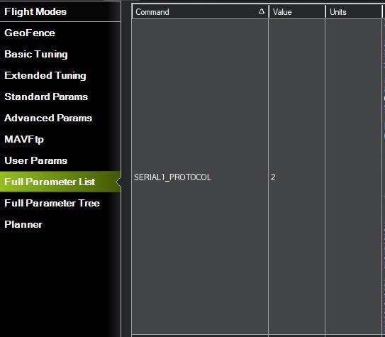
2 | E-identification idME Datasheet
Contents
1 Technical parameters 3
1.1 Basic technical information . . . . . . . . . . . . . . . . . . . . . . . . . . . . . . . . . . . . . . . . 3
1.2 Main features . . . . . . . . . . . . . . . . . . . . . . . . . . . . . . . . . . . . . . . . . . . . . . . . . 3
2 Electrical specification 4
2.1 Basic electrical parameters . . . . . . . . . . . . . . . . . . . . . . . . . . . . . . . . . . . . . . . . 4
2.2 PIN definition . . . . . . . . . . . . . . . . . . . . . . . . . . . . . . . . . . . . . . . . . . . . . . . . . 4
2.3 LED indicators . . . . . . . . . . . . . . . . . . . . . . . . . . . . . . . . . . . . . . . . . . . . . . . . 4
3 Mechanical specification 5
3.1 Mechanical parameters . . . . . . . . . . . . . . . . . . . . . . . . . . . . . . . . . . . . . . . . . . 5
3.2 Dimensions . . . . . . . . . . . . . . . . . . . . . . . . . . . . . . . . . . . . . . . . . . . . . . . . . . 5
3.3 Connectors . . . . . . . . . . . . . . . . . . . . . . . . . . . . . . . . . . . . . . . . . . . . . . . . . . 5
4 Principle of operation 6
4.1 States of operation . . . . . . . . . . . . . . . . . . . . . . . . . . . . . . . . . . . . . . . . . . . . . 6
4.1.1 BOOTLOADER state . . . . . . . . . . . . . . . . . . . . . . . . . . . . . . . . . . . . . . . . 6
4.1.2 RUN state . . . . . . . . . . . . . . . . . . . . . . . . . . . . . . . . . . . . . . . . . . . . . . . 6
4.1.3 CONFIGURATION state . . . . . . . . . . . . . . . . . . . . . . . . . . . . . . . . . . . . . . . 6
4.2 Transitions between states . . . . . . . . . . . . . . . . . . . . . . . . . . . . . . . . . . . . . . . . 6
4.2.1 BOOTLOADER to RUN transition . . . . . . . . . . . . . . . . . . . . . . . . . . . . . . . . 6
4.2.2 RUN to CONFIGURATION transition . . . . . . . . . . . . . . . . . . . . . . . . . . . . . . . 7
4.2.3 CONFIGURATION to RUN transition . . . . . . . . . . . . . . . . . . . . . . . . . . . . . . . 7
4.2.4 CONFIGURATION to BOOTLOADER transition . . . . . . . . . . . . . . . . . . . . . . . . 7
5 UART configuration 8
6 Settings 9
6.1 Write settings . . . . . . . . . . . . . . . . . . . . . . . . . . . . . . . . . . . . . . . . . . . . . . . . 9
6.2 Read settings . . . . . . . . . . . . . . . . . . . . . . . . . . . . . . . . . . . . . . . . . . . . . . . . 9
6.3 Settings description . . . . . . . . . . . . . . . . . . . . . . . . . . . . . . . . . . . . . . . . . . . . 9
6.4 Errors . . . . . . . . . . . . . . . . . . . . . . . . . . . . . . . . . . . . . . . . . . . . . . . . . . . . . . 9
6.5 Command endings . . . . . . . . . . . . . . . . . . . . . . . . . . . . . . . . . . . . . . . . . . . . . 9
6.6 Uppercase and lowercase . . . . . . . . . . . . . . . . . . . . . . . . . . . . . . . . . . . . . . . . 10
6.7 Available settings . . . . . . . . . . . . . . . . . . . . . . . . . . . . . . . . . . . . . . . . . . . . . . 11
6.8 Example . . . . . . . . . . . . . . . . . . . . . . . . . . . . . . . . . . . . . . . . . . . . . . . . . . . . 11
7 Commands 13
7.1 Commands in BOOTLOADER and CONFIGURATION state . . . . . . . . . . . . . . . . . . . . . 13
7.1.1 AT+LOCK . . . . . . . . . . . . . . . . . . . . . . . . . . . . . . . . . . . . . . . . . . . . . . . 13
7.1.2 AT+BOOT . . . . . . . . . . . . . . . . . . . . . . . . . . . . . . . . . . . . . . . . . . . . . . . 13
7.2 Commands in CONFIGURATION state . . . . . . . . . . . . . . . . . . . . . . . . . . . . . . . . . 13
7.2.1 AT+CONFIG . . . . . . . . . . . . . . . . . . . . . . . . . . . . . . . . . . . . . . . . . . . . . . 13
7.2.2 AT+SETTINGS? . . . . . . . . . . . . . . . . . . . . . . . . . . . . . . . . . . . . . . . . . . . 13
7.2.3 AT+HELP . . . . . . . . . . . . . . . . . . . . . . . . . . . . . . . . . . . . . . . . . . . . . . . 13
7.2.4 AT+SETTINGS_DEFAULT . . . . . . . . . . . . . . . . . . . . . . . . . . . . . . . . . . . . . 14
7.2.5 AT+SERIAL_NUMBER . . . . . . . . . . . . . . . . . . . . . . . . . . . . . . . . . . . . . . . 14
7.2.6 AT+FIRMWARE_VERSION . . . . . . . . . . . . . . . . . . . . . . . . . . . . . . . . . . . . . 14
7.2.7 AT+REBOOT . . . . . . . . . . . . . . . . . . . . . . . . . . . . . . . . . . . . . . . . . . . . . 14
7.2.8 AT+REBOOT_BOOTLOADER . . . . . . . . . . . . . . . . . . . . . . . . . . . . . . . . . . . 14
7.3 Commands in RUN state . . . . . . . . . . . . . . . . . . . . . . . . . . . . . . . . . . . . . . . . . . 14
8 Quick start 15
8.1 Configuration . . . . . . . . . . . . . . . . . . . . . . . . . . . . . . . . . . . . . . . . . . . . . . . . . 15
9 Revision history 17
Revision: 23-July-2021 Document Number: 07122021
This document is subject to change without notice. For technical questions, contact: support@aerobits.pl
3         |                                                                   E-identification idME    Datasheet

1     Technical parameters
1.1    Basic technical information
         Parameter                        Description                              Typ.                   Unit
         Frequency                         Bluetooth                           2.402 - 2.480              GHz
        Max. output                 Maximum output power                            +8                    dBm
      ESD protection                    All connectors                                                      -
       Interface baud              Configuraton or MAVLink                       115200                   bps
      Main connector               SM06B-GHS-TB(LF)(SN)                                                     -
     Antenna connector              2x RF-IPX125-1G-AU                                                      -
         Dimension                                                           32.0 x 16.7 x 7.5            mm
    Weight (with antenna)                                                            4                   grams

Table 1: General technical parameters.

1.2     Main features
       • Capability to work with MAVLINK devices
       • BLE broadcast technology compliant with ASTM and ASD-STAN
       • Interfaces: UART, USB

       • Supports Bluetooth 4.0 and 5.2
       • Free Android application available
       • Simple plug&play integration

    Revision: 23-July-2021                                                     Document Number: 07122021
      This document is subject to change without notice. For technical questions, contact: support@aerobits.pl
4 | E-identification idME Datasheet
2 Electrical specification
2.1 Basic electrical parameters
Parameter Value
Input voltage 5V
Current consumption 15 mA
Table 2: General electrical parameters.
Figure 1: Appendant drawing of E-identification idME bottom.
2.2 PIN definition
PIN Color Name Function
1 - GND Ground
2 - NC Not connected
3 - NC Not connected
4 - TX MAVLink, AERO TXD
5 - RX MAVLink, AERO RXD
6 - +5 V Power supply (5 V/ 70 mA)
Table 3: Pin definition.
2.3 LED indicators
LED Color Function
POWER White Power supply indicator
STATUS White Device operation status
Table 4: LED indicators.
Revision: 23-July-2021 Document Number: 07122021
This document is subject to change without notice. For technical questions, contact: support@aerobits.pl5 | E-identification idME Datasheet
3 Mechanical specification
3.1 Mechanical parameters
Parameter Value
Dimensions 32.0 x 16.7 x 7.5mm
Weight 4g
Table 5: Mechanical parameters of E-identification idME
3.2 Dimensions
Figure 2: Dimensions of E-identification idME
3.3 Connectors
Connector Type Example
Main Installed on board SM06B-GHS-TB(LF)(SN)
Mating connector GHR-06V-S
Pins SSHL-002T-P0.2
Antenna Installed on board RF-IPX125-1G-AU
Mating connector GSM-IPX or GSM-IPX/SMA-1G-150
Table 6: Connectors
Revision: 23-July-2021 Document Number: 07122021
This document is subject to change without notice. For technical questions, contact: support@aerobits.pl6 | E-identification idME Datasheet
4 Principle of operation
During work module goes through multiple states. In each state operation of the module is different. Each state and
each transition is described in paragraphs below.
Figure 3: State machine of E-identification idME
4.1 States of operation
4.1.1 BOOTLOADER state
This is an initial state of E-identification idME after restart. Firmware update is possible here. Typically module
transits automatically to RUN state. It is possible to lock module in this state (prevent transition to RUN state) using
one of BOOTLOADER triggers. UART baud is constant and is set to 115200bps. After powering up module, it
stays in this state for up to 3 seconds. If no BOOTLOADER trigger is present, module will transit to RUN state.
Firmware upgrade is possible using Micro ADS-B App software. For automated firmware upgrading scenarios,
aerobits_updater software is available. To acquire this program please contact: support@aerobits.pl.
4.1.2 RUN state
In this state module is broadcasting drone identification data.
4.1.3 CONFIGURATION state
In this mode change of stored settings is possible. Operation of the module is stopped and baud is set to fixed
115200bps. Change of settings is done by using AT-commands. Changes to settings are stored in non-volatile
memory on exiting this state. Additional set of commands is also available in this state, allowing to e.g. reboot
module into BOOTLOADER state, check serial number and firmware version. It is possible to lock module in this
state (similarly to BOOTLOADER) using suitable command.
4.2 Transitions between states
For each of state transitions, different conditions must be met, which are described below. Generally, the only stable
state is RUN. Module always tends to transit into this state. Moving to other states requires host to take some action.
4.2.1 BOOTLOADER to RUN transition
BOOTLOADER state is semi-stable: the module requires additional action to stay in BOOTLOADER state. The
transition to RUN state will occur automatically after short period of time if no action will be taken. To prevent
transition from BOOTLOADER state, one of following actions must be processed:
• Send AT+LOCK=1 command while device is in BOOTLOADER state (always after power on for up to 3s)
• Send AT+REBOOT_BOOTLOADER command in CONFIGURATION state. This will move to BOOTLOADER
state and will lock module in this state.
If none of above conditions are met, the module will try to transit into RUN state. Firstly it will check firmware integrity.
When firmware integrity is confirmed, module will transit into RUN state, if not, it will stay in BOOTLOADER state.
Revision: 23-July-2021 Document Number: 07122021
This document is subject to change without notice. For technical questions, contact: support@aerobits.pl7 | E-identification idME Datasheet
To transit into RUN state:
• If module is locked, send AT+LOCK=0 command
When module enters RUN mode it will send AT+RUN_START command.
4.2.2 RUN to CONFIGURATION transition
To transit from RUN into CONFIGURATION state, host should do one of the following:
• Send AT+CONFIG=1 (using current baud).
When module leaves RUN state it sends AT+RUN_END message, then AT+CONFIG_START message on entering
CONFIGURATION state. The former is sent using baud from settings, the latter always uses 115200bps baud.
4.2.3 CONFIGURATION to RUN transition
To transit from CONFIGURATION into RUN state, host should do one of the following:
• Send AT+CONFIG=0 command.
When module leaves CONFIGURATION state it sends AT+CONFIG_END message, then AT+RUN_START message
on entering RUN state. The former is always sent using 115200bps baud, the latter uses baud from settings.
4.2.4 CONFIGURATION to BOOTLOADER transition
To transit from CONFIGURATION into BOOTLOADER state, host should do one of the following:
• Send AT+REBOOT_BOOTLOADER command.
• Send AT+REBOOT and when module enters BOOTLOADER state, prevent transition to RUN state.
When entering the bootloader state, the module sends AT+BOOTLOADER_START .
Revision: 23-July-2021 Document Number: 07122021
This document is subject to change without notice. For technical questions, contact: support@aerobits.pl8 | E-identification idME Datasheet
5 UART configuration
Communication between module and host device is done using UART interface.
The UART interface uses settings as described in table 7.
UART Settings
Parameter Min. Typ. Max Unit
Baud - 115200 - bps
Stop Bits Number - 1 - -
Flow Control - None - -
Parity Bit - None - -
Table 7: UART settings.
Revision: 23-July-2021 Document Number: 07122021
This document is subject to change without notice. For technical questions, contact: support@aerobits.pl9 | E-identification idME Datasheet
6 Settings
In RUN state, operation of the module is determined based on stored settings. Settings can be changed in CON-
FIGURATION state using AT-commands. Settings can be written and read.
NOTE: New values of settings are saved in non-volatile memory when transitioning from CONFIGURATION
to RUN state.
Settings are restored from non-volatile memory during transition from BOOT do RUN state. If settings become
corrupted due to memory fault, power loss during save, or any other kind of failure, the settings restoration will fail,
loading default values and displaying the AT+ERROR (Settings missing, loaded default) message as a
result. This behavior will occur for each device boot until new settings are written by the user.
6.1 Write settings
After writing a new valid value to a setting, an AT+OK response is always sent.
AT+SETTING=VALUE
For example AT+PROTOCOL=1
Response: AT+OK
6.2 Read settings
AT+SETTING?
For example: AT+PROTOCOL?
Response: AT+PROTOCOL=1
6.3 Settings description
AT+SETTING=?
For example: AT+PROTOCOL=?
Response:
Setting: PROTOCOL
Description: Selected protocol (0: NONE, 2: CSV, 3: MAVLINK)
Type: Integer decimal
Range (min.): 0
Range (max.): 5
Is preserved: 1
Is restart needed: 0
6.4 Errors
Errors are reported using following structure:
AT+ERROR (DESCRIPTION)
DESCRIPTION is optional and contains information about error.
6.5 Command endings
Every command must be ended with one of the following character sequences: “\n”, “\r” or “\r\n”. Commands without
suitable ending will be ignored.
Revision: 23-July-2021 Document Number: 07122021
This document is subject to change without notice. For technical questions, contact: support@aerobits.pl10 | E-identification idME Datasheet
6.6 Uppercase and lowercase
All characters (except preceding AT+) used in command can be both uppercase and lowercase, so following com-
mands are equal:
AT+PROTOCOL?
AT+pRoToCoL?
NOTE: This statement is true in configuration state, not in bootloader state. in bootloader state all letters
must be uppercase.
Revision: 23-July-2021 Document Number: 07122021
This document is subject to change without notice. For technical questions, contact: support@aerobits.pl11 | E-identification idME Datasheet
6.7 Available settings
Setting Min Max Def Comment
BAUDRATE 0 2 0 Baudrate in RUN state
0 - 115200bps
1 - 921600bps
2 - 3000000bps
DRONE_ID_ADVERTISING_ENABLE 0 1 1 Enable Bluetooth advertising
DRONE_ID_SCAN_ENABLE 0 1 0 Enable Bluetooth scan
DRONE_ID_HEIGHT_TYPE 0 1 0 Device Height type
0 - Above Takeoff
1 - AGL
MAVLINK_CONNECTION_TIMEOUT 0 99 5 Mavlink connection timeout in seconds
DRONE_ID_OPERATOR_ID - - - Operator ID (20 bytes )
DRONE_ID_OPERATOR_ID_TYPE 0 255 0 Operator ID type
0 - Operator ID
201-255 - Available for private use
DRONE_ID_OPER_STATUS 0 2 0 Operation status
0 - Undeclared
1 - Ground
2 - Airborne
DRONE_ID_SELF_ID - - - Self ID (20 bytes )
DRONE_ID_SELF_ID_TYPE 0 255 0 Self ID type
0 - Text Description
201-255 - Available for private use
DRONE_ID_STANDALONE 0 1 0 Ignore streams from Mavlink protocol
DRONE_ID_TYPE 0 3 0 UAS ID type
0 - None
1 - Serial Number
2 - CAA Assigned Registration ID
3 - UTM Assigned UUID
DRONE_ID_UAS_TYPE 0 15 0 Specification of the type of UAS
0 - None
1 - Aeroplane
2 - Helicopter or Multirotor
3 - Gyroplane
4 - Hybrid Lift
5 - Ornithopter
6 - Glider
7 - Kite
8 - Free Balloon
9 - Captive Balloon
10 - Airship
11 - Free Fall
12 - Rocket
13 - Tethered Powered Aircraft
14 - Ground Obstacle
15 - Other
DRONE_ID_UAS_NAME - - Device serial number UAS ID (20 bytes)
SETTINGS_DEFAULT Load default settings
Table 8: Settings
6.8 Example
As an example, to set parameter DRONE_ID_OPERATOR_ID for E-identification idME device, one should send fol-
lowing commands. “” is a response.
Revision: 23-July-2021 Document Number: 07122021
This document is subject to change without notice. For technical questions, contact: support@aerobits.pl12 | E-identification idME Datasheet > AT+OK\r\n > AT+OK\r\n >> AT+OK\r\n
13        |                                                                   E-identification idME    Datasheet

7       Commands
Apart from settings, module supports set of additional commands. Format of this commands are similar to those
used for settings, but they do not affect operation of module in RUN state.

7.1     Commands in BOOTLOADER and CONFIGURATION state
7.1.1    AT+LOCK
AT+LOCK=1 - Set lock to enforce staying in BOOTLOADER or CONFIGURATION state
AT+LOCK=0 - Remove lock
AT+LOCK? - Check if lock is set

7.1.2     AT+BOOT
AT+BOOT? - Check if module is in BOOTLOADER state

Response:

AT+BOOT=0 - module in CONFIGURATION state
AT+BOOT=1 - module in BOOTLOADER state

7.2      Commands in CONFIGURATION state
7.2.1     AT+CONFIG
AT+CONFIG=0 - Transition to RUN state.
AT+CONFIG? - Check if module is in CONFIGURATION state.

Response:

AT+CONFIG=0 - module in RUN state
AT+CONFIG=1 - module in CONFIGURATION state

7.2.2     AT+SETTINGS?
AT+SETTINGS? - List all settings. Example output:
AT+PROTOCOL=2
AT+SUBPROTOCOL=0
AT+BAUDRATE=0

7.2.3      AT+HELP
AT+HELP - Show all settings and commands with descriptions. Example output:
SETTINGS:
AT+PROTOCOL=2                 [Selected protocol (0: NONE, 2: CSV, 3: MAVLINK)]
AT+SUBPROTOCOL=0              [Subprotocol of selected protocol]
COMMANDS:
AT+HELP                       [Show this help]
AT+TEST                       [Responds "AT+OK"]
AT+SETTINGS_DEFAULT           [Load default settings]
AT+REBOOT                     [Reboot system]

 Revision: 23-July-2021                                                        Document Number: 07122021
      This document is subject to change without notice. For technical questions, contact: support@aerobits.pl
14 | E-identification idME Datasheet
7.2.4 AT+SETTINGS_DEFAULT
AT+SETTINGS_DEFAULT - Set all settings to their default value.
7.2.5 AT+SERIAL_NUMBER
AT+SERIAL_NUMBER? - Read serial number of module.
Response:
AT+SERIAL_NUMBER=07-0001337
7.2.6 AT+FIRMWARE_VERSION
AT+FIRMWARE_VERSION? - Read firmware version of module.
Response:
AT+FIRMWARE_VERSION=10101017(May 11 2018)
7.2.7 AT+REBOOT
AT+REBOOT - Restart module.
7.2.8 AT+REBOOT_BOOTLOADER
AT+REBOOT_BOOTLOADER - Restart module to BOOTLOADER state.
NOTE: This command also sets lock.
7.3 Commands in RUN state
AT+CONFIG=1 - transition to CONFIGURATION state.
NOTE: This command also sets lock.
Revision: 23-July-2021 Document Number: 07122021
This document is subject to change without notice. For technical questions, contact: support@aerobits.pl15 | E-identification idME Datasheet
8 Quick start
8.1 Configuration
1. Connect appropriate antenna to UFL connector.
2. Configure device settings using Micro ADS-B software via USB or UART interface.
Mavlink dependent mode
3. Connect IdMe to device supports Mavlink V2 protocol. In this example IdMe will be connected to Pixhawk TELEM1
port using JST connectors with not crossed wire(TX and RX are not swiched).
NOTE: In mavlink dependent mode DRONE_ID_STANDALONE parameter should be configure to 0.
4. Using Mission Planner software enable Mavlink V2 protocol on TELEM 1 port.
5. Connect Pixhawk to Mission Planner.
6. Select CONFIG tab.
7. Select Full Parameter List.
Revision: 23-July-2021 Document Number: 07122021
This document is subject to change without notice. For technical questions, contact: support@aerobits.pl16 | E-identification idME Datasheet
8. Find SERIAL1_BAUD parameter and set a value to 115.
9. Find SERIAL1_PROTOCOL parameter and set a value to 2.
10. Reboot Pixhawk.
After configuration device is ready to work when status led starts blinking slowly (once every second).
Revision: 23-July-2021 Document Number: 07122021
This document is subject to change without notice. For technical questions, contact: support@aerobits.pl17 | E-identification idME Datasheet
9 Revision history
Date Revision Changes
21-July-2021 1 Initial release.
Table 9: Revision history.
Revision: 23-July-2021 Document Number: 07122021
This document is subject to change without notice. For technical questions, contact: support@aerobits.pl18 | E-identification idME Datasheet
Please read carefully
Information contained in this document is provided solely in connection with Aerobits products. Aerobits reserves the
right to make changes, corrections, modifications or improvements to this document, and to products and services
described herein at any time, without notice. All Aerobits products are sold pursuant to our own terms and conditions
of sale. Buyers are solely responsible for the choice, selection and use of the Aerobits products and services
described herein, and Aerobits assumes no liability whatsoever, related to the choice, selection or use of Aerobits
products and services described herein. No license, express or implied, by estoppel or otherwise, to any intellectual
property rights is granted under this document. If any part of this document refers to any third party products or
services, it shall not be deemed a license granted by Aerobits for use of such third party products or services, or
any intellectual property contained therein or considered as a warranty covering use, in any manner whatsoever, of
such third party products or services or any intellectual property contained therein.
UNLESS OTHERWISE SET FORTH IN AEROBITS TERMS AND CONDITIONS OF SALE, AEROBITS DISCLAIMS
ANY EXPRESS OR IMPLIED WARRANTY WITH RESPECT TO USE AND/OR SALE OF AEROBITS PRODUCTS
INCLUDING, WITHOUT LIMITATION, IMPLIED WARRANTIES OF MERCHAN-TABILITY, FITNESS FOR A PAR-
TICULAR PURPOSE (AND THEIR EQUIVALENTS UNDER THE LAWS OF ANY JURISDICTION), OR INFRINGE-
MENT OF ANY PATENT, COPYRIGHT OR OTHER INTELLECTUAL PROPERTY RIGHT. UNLESS EXPRESSLY
APPROVED IN WRITING BY AN AUTHORIZED AEROBITS REPRESENTATIVE, AEROBITS PRODUCTS ARE
NOT RECOMMENDED, AUTHORIZED OR WARRAN-
TED FOR USE IN LIFE SAVING, OR LIFE SUSTAINING APPLICATIONS, NOR IN PRODUCTS OR SYSTEMS
WHERE FAILURE OR MALFUNCTION MAY RESULT IN PERSONAL INJURY, DEATH, OR SEVERE PROPERTY
OR ENVIRONMENTAL DAMAGE.
Information in this document supersedes and replaces all previously supplied information.
© 2021 Aerobits - All rights reserved
Revision: 23-July-2021 Document Number: 07122021
This document is subject to change without notice. For technical questions, contact: support@aerobits.plYou can also read