ECPAPE03 Man in cold room alarm Alarm "Personen im Kühlraum" - Use and maintenance manual Technische Bedienungsanleitung - NordCap
←
→
Page content transcription
If your browser does not render page correctly, please read the page content below
ECPAPE03
   Man in cold room alarm
Alarm "Personen im Kühlraum"

 Use and maintenance manual
Technische Bedienungsanleitung
ECPAPE03           - ENG -

                                       ENGLISH

                                          CONTENTS

INTRODUCTION
                                                                                  CHAP. 1
Page   14    1.1               MAN IN COLD ROOM ALARM KIT COMPONENTS
Page   14    1.2               PRODUCT IDENTIFICATION CODES
Page   14    1.3               TECHNICAL CHARACTERISTICS
Page   15    1.4               DIMENSIONS OF ALARM CONTROL UNIT
Page   15    1.5               DIMENSIONS OF EMERGENCY PUSHBUTTON UNIT
Page   15    1.6               IDENTIFICATION DATA
Page   16    1.7               DESCRIPTION OF SYSTEM

INSTALLATION
                                                                                  CHAP. 2
Page 17      2.1               INSTALLING THE OUT-OF-ROOM ALARM CONTROL UNIT
Page 18      2.2               INSTALLING THE IN-ROOM EMERGENCY PUSHBUTTON UNIT
Page 18      2.3               OPERATION AND MAINTENANCE
Page 19      2.4               EXPLODED DIAGRAM
Page 20      2.5               ELECTRICAL CONNECTIONS
Page 21      2.6               WARRANTY TERMS

APPENDICES
Page    22   A.1               EC DECLARATION OF CONFORMITY

                   Rev. 1-09             USE AND MAINTENANCE MANUAL               Pag.13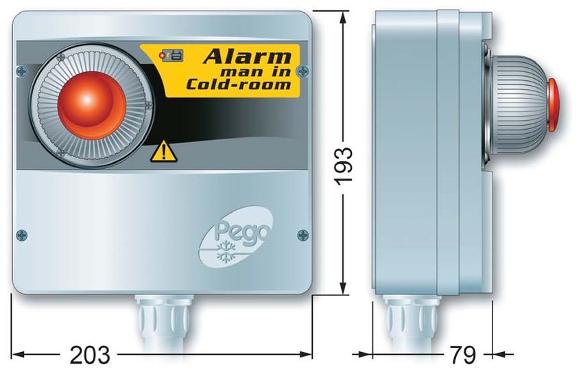
ECPAPE03             - ENG -                                        CHAP. 1 - Introduction

                   CHAPTER 1: INTRODUCTION

      1.1              MAN IN COLD ROOM ALARM KIT COMPONENTS

THE MAN IN COLD ROOM ALARM KIT consists of:

- Visual/acoustic alarm control unit complete with buffer battery.
- N° 3 seals, to be inserted between fixing screw and box backing.
- Emergency cold room light switch.
- Use and maintenance manual.

      1.2                      PRODUCT IDENTIFICATION CODE

    ECPAPE03                                            kit complete with luminous/acoustic man in
                                                        cold room emergency alarm.

    . 1.3                   TECHNICAL CHARACTERISTICS

Mains power supply                230 V AC 50 Hz
Max consumption on mains power    20 mA
Buffer battery                    12 V DC Ni-MH 1300 mAh
                                  Complete recharge time: 110 h
Operating autonomy                - With 230 V AC NOT ON
                                  (running on charged buffer battery) :      14 h approx.

                                  - With 230 V AC power ON:                  unlimited
Out-of-room module                IP 43 protection rating
                                  Operating temperature: -5 - +45 °C
Acoustic characteristics          Type: piezoelectric
                                  Sound power: 90 dB at 1m
Visual warning                    Flashing red LED, 12 V DC
In-room emergency pushbutton      Lighting: red LED, 12 V DC
                                  NC contact
                                  Keypad with IP65 protection rating
                                  Operating temperature: -25 - +70 °C
Auxiliary relay                   8A AC1 (contact closes with alarm on)

 Pag.14           USE AND MAINTENANCE MANUAL                              Rev. 1-09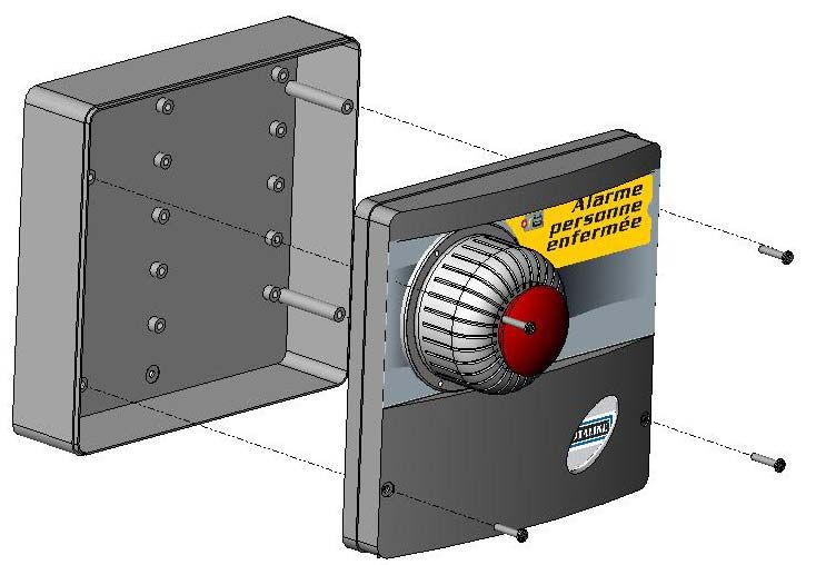
CHAP. 1 - Introduction                                       ECPAPE03           - ENG -

   DIMENSIONS OF ALARM CONTROL UNIT                                                   1.4

            DIMENSIONS OF EMERGENCY PUSHBUTTON UNIT                                  1.5

                                 IDENTIFICATION DATA                                 1.6
The unit described in this manual has, on its side, an ID plate showing all the relevant
identification data:

• Name of Manufacturer
• Code and model of UNIT electrical board
• Serial number
• IP protection rating
• Power supply voltage

               Rev. 1-09             USE AND MAINTENANCE MANUAL                   Pag.15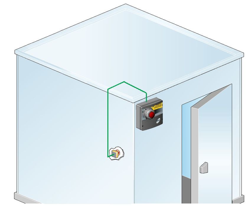
ECPAPE03           - ENG -                                    CHAP. 1 - Introduction

    1.7                        DESCRIPTION OF SYSTEM

The purpose of this safety system is to allow a person trapped inside the cold room to
activate an acoustic/luminous alarm located outside the room and so request help.
The system has been designed to function even in the event of a temporary mains power
failure: in this event the system is powered by a buffer battery housed in the external unit.
The system consists of the following parts:
    • Emergency pushbutton to be fitted inside the cold room.
        Consists of a luminous mushroom-type button with N.C. contact.
        The pushbutton is permanently lit by LEDs so that it can be located in the dark.
    • Acoustic/visual alarm control unit to be fitted outside the cold room.
        Features a siren and flashing light and a buffer battery to provide power in the event
        of a black-out.
        There is also a clean contact (closed with alarm on) that can be used to activate
        other devices such as a remote warning dialler or additional sirens.

Connection between the two devices - consisting of a lead laid by the installer as per the
wiring diagram - is ensured by the system safety logic. Should the lead be cut or
disconnected the alarm will be activated immediately.

 Pag.16         USE AND MAINTENANCE MANUAL                       Rev. 1-09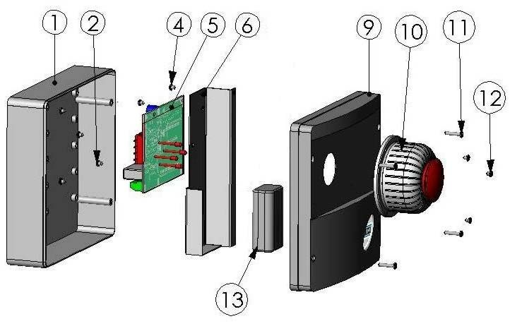
CHAP. 2 - Installation                                         ECPAPE03             - ENG -

+

                   CHAPTER 2: INSTALLATION

     INSTALLING THE OUT-OF-ROOM ALARM CONTROL UNIT                                          2.1

1. Undo the 4 closure screws on the front panel.

2. Use the three existing holes to fix the box back panel to
the wall: use three screws of a length suitable for the
thickness of the wall to which the panel will be attached. Fit a
rubber washer (supplied) between each screw and the box
backing.

Make all the electrical connections as illustrated in the diagram for the corresponding
model (see relative table in APPENDICES). To effect correct electrical connection
and maintain the protection rating, use appropriate wire/raceway grips to ensure a
good seal. Route the wiring inside the unit in as tidy a fashion as possible: be         (
especially careful to keep power wires away from signal wires. Use clips to hold wires in place.

3. Re-close the front panel, making sure that all the wires are inside
the box and that the box seal sits in its seat properly.
Tighten the front panel using the 4 screws, making sure the
O-rings on the head of each screw are used.

                Rev. 1-09                USE AND MAINTENANCE MANUAL                     Pag.17
ECPAPE03          - ENG -                                     CHAP. 2 - Installation

       2.2              INSTALLING THE IN-ROOM EMERGENCY PUSHBUTTON

1. The in-room pushbutton must be positioned so that it is always visible and easily
reachable.

2. Undo the two closure screws on the front of the pushbutton panel.

3. Using the two internal holes fix the box backing with three screws of a length suitable for
the thickness of the wall to which it is to be attached.

       2.3                  OPERATION AND MAINTENANCE

   -    Carry out the connections as per the wiring diagram.
   -    After initial connection it will take 110 hours to fully charge the battery.
   -    Press the luminous pushbutton installed inside the cold room to activate the
        acoustic and luminous warning devices on the external alarm control unit.
        The auxiliary relay contact closes.
   -    In the event of a 230 V AC power failure the buffer battery will intervene and power
        the system for the duration indicated on the technical characteristics chart.
   -    Reset the emergency switch inside the cold room to cancel the alarm.
   -    Periodically check that the buffer battery is working properly.
   -    If the battery is replaced make sure it is disposed of properly at an authorised waste
        collection facility.
   -    If the alarm is tripped without the pushbutton being pressed check the connection
        lead and the connections between the pushbutton and external control unit.

SPARE PARTS:

Buffer battery: ACC12VNIMH

 Pag.18          USE AND MAINTENANCE MANUAL                       Rev. 1-09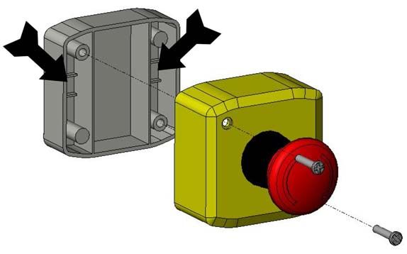
CHAP. 2 - Installation                           ECPAPE03     - ENG -

                            EXPLODED DIAGRAM                     2.4

                              KEY
REF                 DESCRIPTION
1                   BOX BACKING IN ABS
2                   BOARD ATTACHMENT SCREWS
4                   BUFFER BATTERY SUPPORT FIXING SCREWS
5                   BOARD
6                   BUFFER BATTERY SUPPORT METAL SHEETING
9                   FRONTAL SECTION IN ABS
10                  ACOUSTIC/VISUAL ALARM
11                  BOX CLOSURE SCREWS
12                  ACOUSTIC/VISUAL ALARM ATTACHMENT SCREWS
13                  BUFFER BATTERY

            Rev. 1-09         USE AND MAINTENANCE MANUAL      Pag.19
ECPAPE03 - ENG - CHAP. 2 - Installation
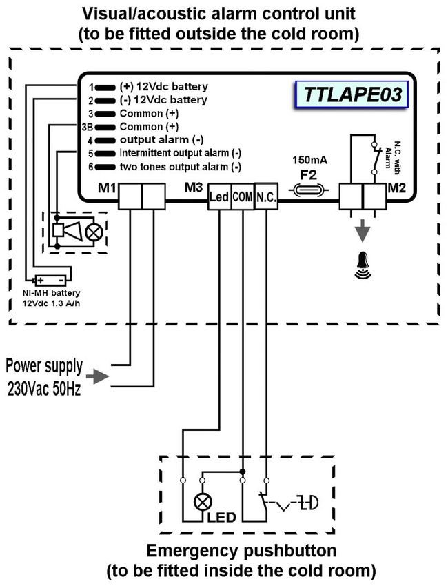
2.5 ELECTRICAL CONNECTIONS
Warning: The positive pole of the battery (Fastom with red wire) is initially disconnected
to maintain the charge during product storage.
Once the in-room keypad connections have been made it is, therefore, necessary to
connect this fastom to the connector marked (1) on the upper left side of the board as also
indicated on the wiring diagram.
It is advisable to first connect the control unit to the relative emergency pushbutton and
only then connect up the battery and the mains power. This will prevent activation of the
alarm.
Pag.20 USE AND MAINTENANCE MANUAL Rev. 1-09CHAP. 2 - Installation ECPAPE03 - ENG -
WARRANTY TERMS 2.6
The man in cold room alarm kit is covered by a 24-month warranty against all
manufacturing defects, valid from date of delivery. If the system malfunctions as a result of
tampering, impact or improper installation the warranty will automatically be rendered null
and void. It is strongly recommended that you observe all instructions/information
regarding the technical characteristics of the device.
Any modifications made to wiring and/or internal components or any work
carried out in a way that fails to comply with the information/instructions in this
manual shall render the warranty null and void immediately.
Modifications/improper work can also cause malfunctions, irreparable damage,
serious injury or put persons/objects in danger.
) PEGO S.r.l. cannot be held liable for possible errors or inaccuracies written in
this manual as a result of printing or transcription errors.
PEGO S.r.l. reserves the right to modify its products as it deems necessary
without altering its main characteristics. Each new release of a PEGO user
manual replaces previous ones.
Rev. 1-09 USE AND MAINTENANCE MANUAL Pag.21ECPAPE03 - ENG - Appendicies
APPENDICES
A.1 EC DECLARATION OF CONFORMITY
COSTRUTTORE / MANUFACTURER
PEGO SRL Via Piacentina,6b 45030 Occhiobello (RO) - ITALY -
DENOMINAZIONE DEL PRODOTTO / NAME OF THE PRODUCT
MOD.: ECPAPE03
IL PRODOTTO E’ CONFORME ALLE SEGUENTI DIRETTIVE CE / THE PRODUCT
COMPLIES WITH THE REQUIREMENTS OF THE FOLLOWING EUROPEAN
DIRECTIVES:
2006/95/CE Direttiva del Consiglio per l’unificazione delle normative dei Paesi CEE relativa al
materiale elettrico destinato ad essere utilizzato entro certi limiti di tensione e
successive modificazioni
2006/95/EC EC Directive on unification of laws of the Member States relating to electrical equipment
employed within certain voltage limits and subsequent amendments
2004/108/CE Direttiva del Consiglio per l’unificazione delle normative dei Paesi CEE relativa
alla compatibilità elettromagnetica e successive modificazioni
2004/108/EC EC Directive on unification of the laws of the Member States relating to electro-magnetic
compatibility and subsequent amendments
93/68 CEE Direttiva del consiglio per la marcatura CE del materiale elettrico destinato ad essere
utilizzato entro talunni limiti di tensione.
93/68 EEC Council Directive for the CE marking of electrical materials to be used within certain limits of
voltage
LA CONFORMITA’ PRESCRITTA DALLE DIRETTIVE E’ GARANTITA DALL’
ADEMPIMENTO A TUTTI GLI EFFETTI DELLE SEGUENTI NORME:
CONFORMITY WITH THE REQUIREMENTS OF THIS DIRECTIVE IS TESTIFIED BY
COMPLETE ADHERENCE TO THE FOLLOWING STANDARDS:
NORMES HARMONISÉES / HARMONIZED EUROPEAN STANDARDS
EN 61000-6–1 EN 61000-6–3 EN 60335 – 1
II Edition II Edition
Pag.22 USE AND MAINTENANCE MANUAL Rev. 1-09ECPAPE03 - DEU -
DEUTSCH
INHALT
EINFüHRUNG
KAP. 1
Seite 34 1.1 BAUTEILE DES BAUSATZES ALARM "MANN IM KÜHLRAUM"
Seite 34 1.2 IDENTIFIZIERUNGSKODIZES DES PRODUKTES
Seite 34 1.3 TECHNISCHE EIGENSCHAFTEN
Seite 35 1.4 AUSMASSE DES ALARMVERTEILERKASTEN
Seite 35 1.5 AUSMASSE DES NOTLEUCHTKNOPFES
Seite 35 1.6 IDENTIFIZIERUNGSDATEN
Seite 36 1.7 SYSTEMBESCHREIBUNG
INSTALLIERUNG
KAP. 2
Seite 37 2.1 INSTALLIERUNG DER ALARMVERTEILERKASTENS AUSSERHALB DES
KÜHLRAUMS
Seite 38 2.2 INSTALLIERUNG DES NOTLEUCHTKNOPFES INNERHALB DES
KÜHLRAUMS
Seite 38 2.3 BETRIEB UND INSTANDHALTUNG
Seite 39 2.4 INNENANSICHT
Seite 40 2.5 ELEKTRISCHE VERBINDUNGEN
Seite 41 2.6 GARANTIEBESTIMMUNGEN
ANLAGEN
Seite 42 A.1 EUROPÄISCHE KONFORMITÄTSBESCHEINIGUNGEN
GEBRAUCHSANWEISUNGEN UND INSTANDHALTUNG
Rev. 1-09 GEBRAUCHSANWEISUNGEN UND INSTANDHALTUNG Pag.33ECPAPE03 - DEU -
KAPITEL 1 : EINFÜHRUNG
1.1 BAUTEILE DES BAUSATZES ALARM "MANN IM KÜHLRAUM"
DER ALARMBAUSATZ "MANN IM KÜHLRAUM" besteht aus:
- Alarmverteilerkasten mit Leucht- und Sirenenalarm und Pufferbatterie.
- 3 Sicherheitsdichtungsringe, die zwischen der Befestigungsschraube und der
Schachtelbasis gelegt wird.
- Notleuchtdruckknopf innerhalb des Kühlraums.
- Gebrauchsanweisung und Instandhaltung.
1.2 IDENTIFIZIERUNGSKODIZES DER PRODUKTE
ECPAPE03 Kompletter Leucht- und Sirenenalarm-
bausatz "Mann im Kühlraum".
. 1.3 TECHNISCHE EIGENSCHAFTEN
Hauptstromverbindung 230 Vac 50 Hz
Max. Stromverbrauch der 20 mA
Hauptstromverbindung
Pufferbatterie 12 VDC Ni-MH 1300 mAh
Komplette Ladedauer: 110 h
Betriebsautonomie - Mit Unterbrechung der 230Vac Hauptstromverbindung
(Betrieb mit geladener Pufferbatterie) : 14 h circa
- Mit Hauptstromverbindung 230Vac : unbegrenzt
Externes Modul Schutzgrad IP 43
Betriebstemperatur: -5 ÷ +45 °C
Akustische Eigenschaften Typ: piezoelektrisch
Pegelstärke: 90 dB in 1m Entfernung
Leuchtalarm Blinklichtdiode rot 12 Vdc
Notleuchtdruckknopf im inneren Beleuchtung: rote Diode 12 Vdc
Bereich des Kühlraums NC Kontakt
Schaltpult mit Schutzgrad IP65
Betriebstemperatur: -25 ÷ +70 °C
Hilfsrelais 8A AC1 (Kontakt schlieβt bei Alarm)
Pag.34 GEBRAUCHSANWEISUNGEN UND INSTANDHALTUNG Rev. 1-09KAP. 1 - Einführung ECPAPE03 - DEU -
AUSMAβE DES ALARMVERTEILERKASTENS 1.4
AUSMAβE DES NOTLEUCHTKNOPFES 1.5
IDENTIFIZIERUNGSDATEN 1.6
Das in diesem Handbuch beschriebene Gerät ist mit einem seitlichen Schildchen
versehen, das die Identifizierungsdaten wiedergibt:
• Name des Herstellers
• Kodex und Modell des elektrischen Schaltpults
• Matrikelnummer
• IP Schutzgrad
• Stromspannung
Rev. 1-09 GEBRAUCHSANWEISUNGEN UND INSTANDHALTUNG Pag.35ECPAPE03 - DEU - KAP. 1 - Einführung
1.7 SYSTEMBESCHREIBUNG
Dieses Sicherheitssystem hat die Aufgabe, einen auβerhalb des Kühlraums angebrachten
Leucht- und Akustikalarm zu aktivieren sobald eine Person im Kühlraum eingeschlossen
bleiben sollte. Das System ist so geschaffen, dass es auch im Falle eines Black-outs des
Stromnetzes funktioniert, dank einer Pufferbatterie die sich im äuβeren Bereich befindet.
Die Bauteile des Systems sind folgende:
• Notschalteinheit für den internen Bereich des Kühlraums.
Sie besteht aus einem Leuchtdruckknopf mit N.C. Verbindung
Die Dioden des Notleuchtdruckknopfes sind ständig beleuchtet damit er auch im
Dunkeln sichtbar ist.
• Leucht- und Sirenenalarmverteilerkasten für den externen Bereich des
Kühlraums.
Er besteht aus einer Sirene, einem Blinklicht um den Alarm zu signalisieren und
einer Pufferbatterie für den Fall eines Black-outs. Es ist u. a. eine separate
Verbindung vorgesehen (geschlossen aber aktiv), um weitere
Sicherheitsvorkehrungen verbinden zu können wie z. B. ein automatisches
Telefonsignal oder zusätzliche Alarmsirenen.
Die Verbindung der zwei Sicherheitseinrichtungen besteht aus einem vom Installateur
gemäβ Plan verlegten Kabel und ist durch die Logik des Sicherheitssystems garantiert.
Falls die Stromleitung durchgetrennt oder abgeschaltet wird, setzt sich das Alarmsystem
automatisch ein.
Pag.36 GEBRAUCHSANWEISUNGEN UND INSTANDHALTUNG Rev. 1-09KAP. 2 - Installierung ECPAPE03 - DEU -
KAPITEL 2: INSTALLIERUNG
INSTALLIERUNG DER NOTSCHALTEINHEIT AUβERHALB DES KÜHLRAUMS 2.1
1. Die vier auf der Frontseite befestigten.
Schrauben abschrauben.
2. Mittels der drei vorgefertigten Schraublöchern und
den drei der Stärke der Wand angemessenen
Schrauben an der die Schalteinheit befestigt werden
soll, die Schachtelbasis anschrauben. Die mitgelieferte
Gummibeilagscheibe zwischen die Schachtelbasis und
Schraube legen.
Alle elektrischen Anschlüsse gemäβ den beigelegten Zeichnungen des bezüglichen Modells
verbinden (man siehe die Tabellen in den ANLAGEN). Um die elektrischen Anschlüsse zuverlässig
zu verbinden und um die Schachtel unversehrt zu lassen, ratet man eigene Kabelpressen und/oder
Rohrpressen für die Verkabelung zu benützen. Weiters empfiehlt man den Durchgang der
Leitungen innerhalb des Schaltpults so ordentlich wie nur möglich zu verlegen. Man sollte vor
allem beachten die Stromleitungen von den Signalleitungen gut entfernt zu halten. Eventuell
Sicherheitskabelschellen verwenden.
3. Den Frontaldeckel schlieβen. Sorgfältig darauf achten,
dass sich alle Kabel im Inneren der Schachtel befinden und
dass die Schachtelabdichtung richtig sitzt. Den Frontdeckel
mit den 4 Schrauben schlieβen indem man die O-Ringe am
Hals jeder Schraube wieder verwendet.
Rev. 1-09 GEBRAUCHSANWEISUNGEN UND INSTANDHALTUNG Pag.37ECPAPE03 - DEU - KAP. 2 - Installierung
INSTALLIERUNG DES NOTLEUCHTDRUCKKNOPFES INNERHALB DES KÜHLRAUMS
2.2
1. Der Druckknopf innerhalb des Kühlraums sollte an einer erreichbaren und gut
sichtlichen Position installiert werden.
2. Die zwei Verschlussschrauben auf der Frontseite der Schachtel abschrauben.
3. Mittels der zwei vorgefertigten Schraublöchern und den der Stärke der Wand
angemessenen Schrauben, die Schachtelbasis anschrauben
2.3 BETRIEB UND INSTANDHALTUNG
- Die elektrische Verkabelung gemäβ Plan verlegen.
- Nach der Erstverbindung sind 110 Stunden Ladezeit der Batterien notwendig.
- Den internen Notleuchtdruckknopf drücken um die Alarmsirene und das
Alarmblinklicht des externen Verteilerkastens zu aktivieren. Der Kontakt des
Sicherheitsrelais wird geschlossen.
- Im Falle einer Unterbrechung der 230 Vac Stromzufuhr, kommt die Pufferbatterie
zum Einsatz um das System für die in den technischen Angaben erklärte Dauer
weiterlaufen zu lassen.
- Den Sicherheitskontakt im Innern des Kühlraums wiederherstellen um die
Alarmierung abzubrechen.
- Die Pufferbatterie periodisch auf Effizienz kontrollieren.
- Falls die Pufferbatterie ausgetauscht werden sollte, bitte die alte Batterie auf dem
Sondermüll entsorgen.
- Falls sich das Alarmsystem auch ohne Betätigung des Alarmknopfes auslöst, bitte
die Unversehrtheit der Verkabelung zwischen Druckknopf und externen
Warnanlage kontrollieren.
ERSATZTEILE:
Pufferbatterie: ACC12VNIMH
Pag.38 GEBRAUCHSANWEISUNGEN UND INSTANDHALTUNG Rev. 1-09KAP. 2 - Installierung ECPAPE03 - DEU -
INNENANSICHT 2.4
LEGENDE
BEZ BESCHREIBUNG
1 HINTERE SCHACHTEL AUS ABS
2 BEFESTIGUNGSSCHRAUBEN
4 BEFESTIGUNGSSCHRAUBEN DER
PUFFERBATTERIEHALTERUNG
5 PLATINE
6 BLECHUNTERLAGE DER PUFFERBATTERIE
9 FRONTALE SCHACHTEL AUS ABS
10 SIRENE UND LEUCHTALARM
11 SCHRAUBEN ZUR VERSCHLIESSUNG DER
SCHACHTEL
12 VERSCHLUSSSCHRAUBEN FÜR SIRENE UND
LEUCHTALARM
13 PUFFERBATTERIE
Rev. 1-09 GEBRAUCHSANWEISUNGEN UND INSTANDHALTUNG Pag.39ECPAPE03 - DEU - KAP. 2 - Installierung
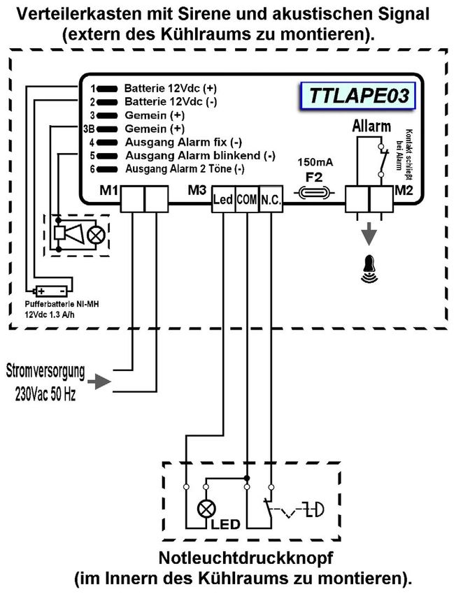
2.5 ELEKTRISCHE VERKABELUNG
Achtung: der positive Pol der Batterie (Fastom mit rotem Kabel) ist anfänglich nicht
verbunden um die Ladung derselben während der Lagerung des Produkts beizubehalten.
Nach der Verkabelung ist es deshalb notwendig den Fastom mit dem Verbindungsstück
(1) das sich oben links auf der Platine befindet, zu verbinden (auch auf den elektrischen
Plan erkennbar).
Man empfiehlt zuallererst den Verteilerkasten mit dem Notleuchtdruckknopf zu verbinden
und erst dann die Batterie und die Stromverbindung, um die sofortige Aktivierung des
Alarms zu vermeiden.
Pag.40 GEBRAUCHSANWEISUNGEN UND INSTANDHALTUNG Rev. 1-09KAP. 2 - Installierung ECPAPE03 - DEU -
GARANTIEBEDINGUNGEN 2.6
Der Alarmbausatz "Mann im Kühlraum" ist gegen alle Fabrikationsschäden für die Dauer
von 24 Monaten ab Lieferdatum garantiert. Schäden die auf direktes Eingreifen, Stöβen
oder durch eine nicht fachgerechte Installierung verursacht worden sind, sind nicht von der
Garantie gedeckt. Man empfiehlt die technischen Eigenschaften während des Betriebs zu
beachten.
ACHTUNG !
Eingriffe die die elektrische Verkabelung und/oder interne Bauteile
beeinflussen oder verändern, nicht fachgerecht oder nicht gemäβ den
mitgelieferten Zeichnungen durchgeführt werden, haben einen sofortigen
Verfall der Garantie zur Folge. Auβerdem können sie beachtliche Schäden,
defekten Betrieb oder Gefahren für Personen oder Sachschäden hervorrufen.
) PEGO lehnt jede Verantwortung die auf Druckfehler oder Textübertragung des
vorliegenden Handbuchs zurückzuführen sind, ab.
PEGO behält sich das Recht vor an den eigenen Produkten solche Änderungen
vorzunehmen die sie für notwendig oder nützlich hält und nicht die
grundlegenden Eigenschaften des Produkts verändern.
Jede Handbuchneuausgabe der PEGO produkte ersetzt alle vorher verteilten
Handbücher.
Rev. 1-09 GEBRAUCHSANWEISUNGEN UND INSTANDHALTUNG Pag.41ECPAPE03 - DEU - Anlagen
ANLAGEN
A.1 EC DECLARATION OF CONFORMITY
COSTRUTTORE / MANUFACTURER
PEGO SRL Via Piacentina,6b 45030 Occhiobello (RO) - ITALY -
DENOMINAZIONE DEL PRODOTTO / NAME OF THE PRODUCT
MOD.: ECPAPE03
IL PRODOTTO E’ CONFORME ALLE SEGUENTI DIRETTIVE CE / THE PRODUCT
COMPLIES WITH THE REQUIREMENTS OF THE FOLLOWING EUROPEAN
DIRECTIVES:
2006/95/CE Direttiva del Consiglio per l’unificazione delle normative dei Paesi CEE relativa al
materiale elettrico destinato ad essere utilizzato entro certi limiti di tensione e
successive modificazioni.
2006/95/EC EC Directive on unification of laws of the Member States relating to electrical equipment
employed within certain voltage limits and subsequent amendments.
2004/108/CE Direttiva del Consiglio per l’unificazione delle normative dei Paesi CEE relativa
alla compatibilità elettromagnetica e successive modificazioni
2004/108/EC EC Directive on unification of the laws of the Member States relating to electro-magnetic
compatibility and subsequent amendments.
93/68 CEE Direttiva del consiglio per la marcatura CE del materiale elettrico destinato ad essere
utilizzato entro talunni limiti di tensione.
93/68 EEC Council Directive for the CE marking of electrical materials to be used within certain limits of
voltage.
LA CONFORMITA’ PRESCRITTA DALLE DIRETTIVE E’ GARANTITA DALL’
ADEMPIMENTO A TUTTI GLI EFFETTI DELLE SEGUENTI NORME:
CONFORMITY WITH THE REQUIREMENTS OF THIS DIRECTIVE IS TESTIFIED BY
COMPLETE ADHERENCE TO THE FOLLOWING STANDARDS:
NORMES HARMONISÉES / HARMONIZED EUROPEAN STANDARDS
EN 61000-6–1 EN 61000-6–3 EN 60335 – 1
II Edition II Edition
Pag.42 GEBRAUCHSANWEISUNGEN UND INSTANDHALTUNG Rev. 1-09- ITA - ECPAPE03
NOTE
Rev. 1-09 Pag.43Cool Italia GmbH Schmidener Weg 13 D – 70736 Fellbach Tel.: + 49 (0) 711 / 65883-15 Fax.: + 49 (0) 711 / 653602 e-mail: info@coolitalia.de
You can also read