Energy Resource Interconnection Service and Network Resource Interconnection Service (Q137) - Prepared by: December 1, 2016
←
→
Page content transcription
If your browser does not render page correctly, please read the page content below
Facilities Study Report

 Energy Resource Interconnection Service and Network Resource Interconnection Service (Q137)

Prepared by:

Shady Hills (Q137) Facilities Study                               Date:     December 1, 2016
Facilities Study Report

Table of Contents
1.0     Introduction ...................................................................................................................................... 4
2.0     Baseline Assumptions ....................................................................................................................... 5
3.0     Required Network Upgrades ............................................................................................................ 6
  3.1      Transmission Lines ........................................................................................................................ 6
      3.1.1        Work Scope ........................................................................................................................... 6
      3.1.2        Clarifications and Assumptions ............................................................................................. 6
      3.1.3        Transmission Line Cost Estimate ........................................................................................... 7
  3.2      Substation Physical ....................................................................................................................... 8
      3.2.1        Work Scope ........................................................................................................................... 8
      3.2.2        Clarifications and Assumptions ........................................................................................... 10
      3.2.3        Cost Estimate ...................................................................................................................... 11
  3.3      Protection and Control................................................................................................................ 12
      3.3.1        Work Scope ......................................................................................................................... 12
      3.3.2        Clarifications and Assumptions ........................................................................................... 14
      3.3.3        Protection and Control Cost Estimate ................................................................................ 15
  3.4      Telecommunications ................................................................................................................... 15
      3.4.1        Work Scope ......................................................................................................................... 16
      3.4.2        Clarifications and Assumptions ........................................................................................... 16
      3.4.3        Telecommunications Cost Estimate .................................................................................... 17
4.0     Connection Requirements .............................................................................................................. 18
  4.1      General ........................................................................................................................................ 18
  4.2      Point of Interconnection ............................................................................................................. 18
  4.3      Short Circuit Withstand Capability .............................................................................................. 18
  4.4      Equipment Ratings ...................................................................................................................... 18
  4.5      Insulation Requirements ............................................................................................................. 18
  4.6      Instrument Transformer Requirements ...................................................................................... 19
  4.7      Communications ......................................................................................................................... 19
  4.8      Metering...................................................................................................................................... 19
5.0     Cost Estimate Summary .................................................................................................................. 20

Shady Hills (Q137) Facilities Study                                                                            Date:          December 1, 2016
                                                                  Page 2 of 24
Facilities Study Report

  5.1      Milestone Schedule ..................................................................................................................... 20
6.0     Appendix ‐ Transmission Lines ‐ Lines Routes – and Substation 3‐Lines ....................................... 21
7.0     Facilities Study Approval ................................................................................................................. 24

Shady Hills (Q137) Facilities Study                                                                       Date:         December 1, 2016
                                                               Page 3 of 24
Facilities Study Report
1.0 Introduction
EFS Shady Hills LLC (Customer) has submitted an Interconnection Request (Q137) on Duke Energy
Florida’s (DEF’s) system for a new combined cycle generating unit capable of 500 MW summer and
520 MW winter output. The request was to evaluate this new generation for Energy Resource
Interconnection Service (ERIS) and Network Resource Interconnection Service (NRIS) with a
proposed Commercial Operating Date (COD) of June 1, 2020. The generating facility will be located
adjacent to the existing Shady Hills Plant in Spring Hill Florida.
DEF previously completed a System Impact Study (SIS) report on July 29, 2016, that summarizes
the thermal, voltage, short circuit and transient stability impacts associated with the proposed
interconnection.
The primary objective of the Facilities Study (FS) is to quantify necessary Transmission Owner
network upgrade(s), other direct assigned upgrade(s), and associated upgrade lead times.
Therefore, this FS quantifies the cost, work scope, and tentative schedules associated with the
design and installation of the required network modifications. This study evaluates and estimates
the earliest dates service that could be granted based on specific criteria outlined within this report.
The SIS results indicate that the interconnection of the new generating unit would require the
following new and upgraded facilities prior to the Q137 COD:
1. A new three (3) breaker 230 kV ring bus switching station called Hudson North is proposed.
The existing Brooksville West to Seven Springs 230kV line will be looped into this station.
See 3‐line diagram of the proposed station in appendix A3. It is proposed that this new
switching station be located adjacent to the existing Brooksville West to Seven Springs
230kV line approximately 0.5 miles west of the existing Shady Hills Plant.
2. Rebuilding of the Crystal River Plant to Bronson 230 kV line (38 miles).
3. Construction of a new (third) Powerline to Holder 230 kV line (11.5 miles)
The FS includes cost estimates to permit, engineer, procure equipment and materials, construct and
place facility upgrades or additions in service to accomplish the requested service.
The projects required to provide ERIS and NRIS have been reviewed and proposed schedules for
completion were based on the assumption that the DEF and Customer execute an
Agreement/Contract by July 3, 2017. Schedules were developed utilizing typical project durations
experienced by DEF for project engineering, procurement, permitting, right of way acquisition,
construction, and outage requirements. Schedules also consider seasonal capacity considerations as
well as system configuration constraints such as concurrent line outages.
Shady Hills (Q137) Facilities Study Date: December 1, 2016
Page 4 of 24Facilities Study Report
Subsequent to the requirements and preparation listed in this document a design review shall take
place prior to any facilities construction to maintain compliance with the North American Electric
Reliability Corporation (NERC) Reliability Standard FAC‐002‐1, or its successor.
Also in compliance with the NERC Reliability Standard FAC‐002‐1, or its successor, a testing and
inspection activity will take place prior to the in‐service date.
2.0 Baseline Assumptions
The Transmission Company’s (DEF’s) Facilities are based on application of industry standard
equipment. All new and rebuilt facilities will be designed and built according to the DEF’s current
practice. As such the total energy handling capability of the proposed network modifications could
potentially accommodate energy flows greater than the requested 500 MW (Summer) / 520 MW
(Winter) in the Q137 request. In the event the Customer decides to designate additional capacity, a
new request will be required to evaluate the impacts. Any constraints that may result will be
identified as part of the new study request.
Any required outages necessary to support construction of the DEF Associated Facilities must be
coordinated with the DEF Energy Control Center (“ECC”). If an outage of sufficient duration cannot
be obtained to support any of the required construction activities, alternative solutions such new
facilities or temporary facilities may have to be constructed to maintain integrity of grid. No
provisions have been made for temporary work in the estimates provided herein.
The proposed protection schemes to be installed by DEF at its Associated Facilities are intended to
protect DEF’s Transmission Network.
It is assumed that the new Powerline substation will be in‐service, the Bronson Line terminal will
be upgraded at Crystal River Plant and the connection of the Brookridge to Hudson 230 kV line into
the Brooksville West substation will all be complete prior to the construction of the upgrades
associated with Q137 and are therefore not included in the scope of work.
Estimates prepared for this FS are considered to be good faith estimates represented in present day
dollars as of the date of the study. The estimates do not include upgrade costs for third party
facilities. The cost estimates provided use currently available pricing in Duke’s estimating system.
The estimated budget has been computed with an expected accuracy of +/‐20 %. Costs may
fluctuate due to inflation or changes in market price. The estimates are further premised on being
able to perform work during normal business hours with minimum overtime or weekend work.
Shady Hills (Q137) Facilities Study Date: December 1, 2016
Page 5 of 24Facilities Study Report
3.0 Required Network Upgrades
3.1 Transmission Lines
The transmission line scope changes of the facilities that are required to support this transmission
service are addressed by the following sections.
3.1.1 Work Scope
The result of the SIS requires the following network upgrades in support of the Q137
interconnection request:
3.1.1.1 Crystal River Plant to Bronson
Rebuild the existing line to a higher capacity. Current DEF practice is to utilize 3000A capacity
lines with 2627 KCM ACSS/TW/HS Santee conductor. See Appendix A1.
3.1.1.2 Powerline to Holder
Build a new Transmission Line from the proposed Powerline Substation to the existing Holder
Substation. Current DEF practice is to utilize 3000A capacity lines with 2627 KCM ACSS/TW/HS
Santee conductor. See Appendix A2 with proposed new route.
3.1.1.3 Loop Brooksville West to Seven Springs 230 kV line into Hudson North
Loop the existing Brooksville West to Seven Springs 230 kV line (CRS) into the proposed
Hudson North Switching station.
3.1.2 Clarifications and Assumptions
The estimate assumes no changes in scope or design from that provided in previous studies.
It is assumed that the outages/clearances required for construction are compatible with
load flow conditions at the time of construction. These projects require several and difficult
to obtain outages which could delay or increase the cost of this project, if they are not
received in a timely manner.
Permitting costs have been allotted based on historical costs. If permitting requirements
(Including mitigation, fill work and landscaping requirements) are increased then the
estimate will increase accordingly.
Cost estimates are all‐inclusive of engineering, material (structures, conductors, OPGW,
etc.), survey, geotechnical, access, clearing, easements, siting, environmental, construction
and removal.
This study does not consider third party components or impacts.
The Crystal River to Bronson line will be rebuilt in the existing right‐of‐way.
Shady Hills (Q137) Facilities Study Date: December 1, 2016
Page 6 of 24Facilities Study Report
The new Powerline to Holder line will be built in the existing Crystal River Plant to Central
Florida right‐of‐way.
The new Powerline substation will be in‐service, prior to the construction of the upgrades
associated with Q137 and is therefore not included in the scope of work.
The connection of the Brookridge to Hudson 230 kV line into the Brooksville West
Substation will be complete prior to the construction of the upgrades associated with Q137
and is therefore not included in the scope of work.
The Customer will build the generator lead line from the Shady Hills Plant to the new
Hudson North switching station.
3.1.3 Transmission Line Cost Estimate
Delivery Monitored Facility Type Estimated Cost*
($)
Q137 Shady 230 kV Line S/C from Powerline Sub to Holder
New $ 32,054,000
Hills Plant Substation
Q137 Shady 230 kV Line S/C from Crystal River Plant Sub Rebuild $ 93,393,000
Hills Plant to Bronson Sub
Loop Brookville West to Seven Spring (CRS)
Q137 Shady
230 kV line into the new Hudson North New $ 1,708,000
Hills Plant Switching Station
Total $ 127,155,000
Shady Hills (Q137) Facilities Study Date: December 1, 2016
Page 7 of 24Facilities Study Report
3.2 Substation Physical
3.2.1 Work Scope
The physical scope of work identified in this study is listed below. For all the equipment identified:
Bus, jumpers, switches, breakers, connectors etc. shall be installed to have a minimum
continuous current rating of 3000A.
230kV breakers shall have a minimum 63kA interrupting capability.
The scope of work shall include any associated work required for the installation which are
but not limited to: lightning protection, insulation coordination, yard lightning, grounding,
conduit, trench, station auxiliary systems, bus design, structures, foundations, drainage,
fencing, rock, siting, permits, environmental studies and mitigations.
A. Bronson Substation (230kV)
Upgrade the Crystal River Plant line position at Bronson. The scope of work includes:
Upgrade five (5) 230kV, 3000A, disconnect switches. Includes four (4) breaker switches and
one (1) motor operated line switch.
Upgrade two (2) 230kV, 3000A, breakers
Upgrade single conductors to double 1750 AAC
Removal of one (1) 230kV wave trap
Installation of new raceway for fiber
B. Brooksville West Substation (230kV)
The existing Seven Springs terminal at Brooksville West will be redesignated Hudson North. The
scope of work includes:
Updating substation drawings to reflect new terminal designation.
C. Crystal River Plant Substation (230kV)
The scope of work at the Crystal River Plant substation includes:
Removal of two (2) 230kV wave traps.
The existing Bronson terminal at Crystal River Plant is currently being upgraded to 3000A by a
separate project. See Clarifications and Assumptions section 3.2.2 below.
D. Holder Substation (230kV)
Install a new line position at Holder for a third Powerline substation line. The scope of work
includes the installation of:
Shady Hills (Q137) Facilities Study Date: December 1, 2016
Page 8 of 24Facilities Study Report
Three (3) 230kV, 3000A, disconnect switches. Includes two (2) breaker switches and one
(1) motor operated line switch.
Two (2) 230kV, 3000A, breakers
One (1) 230kV, deadend tower
Three (3) 230kV CCVTs
Three (3) 230kV surge arresters
Complete 230kV ring bus
4” IWCB bus & double 1750 AAC jumpers
E. Hudson North Substation (230kV)
A new Hudson North substation is proposed for the interconnection of Q137. Install a two (2) bay
230kV breaker and half yard. The breaker and half bays will be initially configured in a ring bus and
include two (2) 230kV transmission line positions and one (1) 230kV line position for the Q137
interconnection. The 230kV line switch at the Q137 interconnection line position will be controlled
by DEF. DEF reserves the right to lock it in the open position. See 3‐line diagram of the proposed
station in appendix A3.
The scope of work the installation of:
Three (3) 230kV, deadend towers
Nine (9) 230kV, 3000A, disconnect switches. Includes six (6) breaker switches and three (3)
motor operated line switches.
Three (3) 230kV, 3000A, breakers
4” IWCB bus & double 1750 AAC jumpers
Three (3) Free Standing CTs for metering
Twelve (12) 230kV CCVTs. Includes nine (9) CCVTs for protection and three (3) CCVTs for
intertie metering.
Nine (9) 230kV surge arresters
One (1) medium size CEE
Shady Hills (Q137) Facilities Study Date: December 1, 2016
Page 9 of 24Facilities Study Report
F. Powerline Substation (230kV)
Install a new line position at Powerline for a third Holder line. The scope of work includes the
installation of:
Five (5) 230kV, 3000A, disconnect switches. Includes four (4) breaker switches and one (1)
motor operated line switch.
Two (2) 230kV, 3000A, breakers
One (1) 230kV, deadend tower
Three (3) 230kV CCVTs
Three (3) 230kV surge arresters
4” IWCB bus & double 1750 AAC jumpers
The Powerline substation is a proposed substation. It is being engineered, procured, and
constructed by a separate project. See Clarifications and Assumptions section 3.2.2 below.
G. Seven Springs Substation (230kV)
The existing Brooksville West terminal at Seven Springs substation will be redesignated Hudson
North. The scope of work includes:
Updating substation drawings to reflect new terminal designation.
This terminal is currently being upgraded to 3000A by a separate project. See Clarifications and
Assumptions section 3.2.2 below.
3.2.2 Clarifications and Assumptions
This report does not consider possible environmental (wetlands, soil contamination,
asbestos, lead paint, chemical spray etc.) mitigation. Testing and environmental
assessments are required to identify and quantify environmental costs. These items are
outside the scope of this study.
The ability to utilize standard and typical foundations is assumed.
AC load studies are outside the scope of this document. It is assumed that existing AC
systems at substations have sufficient capacity for the proposed additions. However, future
AC load studies are required to determine the adequacy of AC systems.
Third party impacts are outside the scope of this estimate. It is assumed that separate
facilities studies will be completed by others to capture impacts at those locations.
This report assumes the ability to acquire a suitable site adjacent to the existing Duke right
of way for the proposed Hudson North substation. Cost estimates in this report assume
Shady Hills (Q137) Facilities Study Date: December 1, 2016
Page 10 of 24Facilities Study Report
typical cost of the following siting and real estate items: land purchase, clearing, fill, grading,
and drive access. Unique siting and real estate situations are possible; however, they
depend on site selection and availability and are not accounted for in this report.
There is a proposed project to loop the existing Brookridge to Hudson line into the
Brooksville West substation. It is assumed this work is completed prior to the
interconnection of Q137.
There is an existing project to upgrade the Bronson line terminal at the Crystal River Plant
substation. It is assumed this upgrade work is completed prior to the interconnection of
Q137.
There is an existing project to upgrade the existing Brooksville West line terminal at the
Seven Springs substation. It is assumed this upgrade work is completed prior to the
interconnection of Q137.
There are plans to build a new Powerline substation and install and loop the two (2) Crystal
River Plant to Holder lines into Powerline 230kV transmission lines. It is assumed this work
is completed prior to the interconnection of Q137.
3.2.3 Cost Estimate
A summary of the estimated cost for the substation physical scope of work is listed in the table
below.
Substation Sum of Cost
Bronson Substation $1,286,000
Brooksville West Substation $9,000
Crystal River Plant Substation $18,000
Holder Substation $2,347,000
Hudson North Substation $8,655,000
Powerline Substation $1,662,000
Seven Springs Substation $9,000
Grand Total $13,986,000
Shady Hills (Q137) Facilities Study Date: December 1, 2016
Page 11 of 24Facilities Study Report
3.3 Protection and Control
3.3.1 Work Scope
Protection system addition or upgrades shall be implemented with full redundancy. New breakers
will utilize a breaker control relay and a breaker failure relay, with current supervision, from a
separate bushing current transformer on the breaker. Should a breaker fail to trip within the
allowable time setting, the associated breaker failure trip relay and associated lockout relay will
trip and lock out adjacent breakers and remote breakers via breaker failure transfer trip.
The transmission line protective relay schemes continuously monitor conditions of the
transmission lines and are designed to detect and isolate the faults with maximum speed and
minimum disturbance to the system. The transmission lines will be protected by redundant Line
Protection 1 and Line Protection 2 current differential relays designed to clear a fault on the line.
The schemes will use relay‐to‐relay communications utilizing fiber optic cable.
The 230kV protection & control for a two breaker line shall include items listed the following table:
Total Device Function
Qty
1 SEL‐311L Line Protection 1
1 SEL‐411L Line Protection 2
1 86‐LOR/ER Breaker Failure Transfer Trip Lockout (Elec
Reset)
1 SEL‐351S MOS Control
2 SEL‐351S Breaker Control
2 SEL‐451 Breaker Failure
2 86‐LOR Breaker Failure Lockout
Items listed in the above table are collectively referred to as “P&C line package” in subsequent
scope items.
The protection & control scope of work identified in this study is listed below:
A. Bronson Substation (230kV)
Upgrade the Crystal River Plant line position at Bronson. The scope of work includes:
Removal of the existing power line carrier equipment
Installation of communication equipment for fiber assisted protection
B. Brooksville West Substation (230kV)
The existing Seven Springs terminal at Brooksville West will be redesignated Hudson North. The
scope of work includes:
Revision of P&C drawings, documents, and relay settings
Shady Hills (Q137) Facilities Study Date: December 1, 2016
Page 12 of 24Facilities Study Report
C. Crystal River Plant Substation (230kV)
Upgrade the Bronson line position at Crystal River Plant. The scope of work includes the
installation of:
Removal of the existing power line carrier equipment
Installation of communication equipment for fiber assisted protection
D. Holder Substation (230kV)
Install a new line position at Holder for a third Powerline line. The scope of work includes the
installation of:
One (1) P&C line package
E. Hudson North Substation (230kV)
Install a two (2) bay 230kV breaker and half yard at the proposed Hudson North substation. The
new breaker and half bays will be configured in a three (3) breaker ring bus and include two (2)
new line positions and one position for the Q137 interconnection.
For a 230 kV breaker failure contingency, the BFBU time should be 12.0 cycles and the DTT to the
adjacent facility 1.0 cycle. There should be two independent HSPP groups. The 230 kV Hudson
North substation is classified as Type 1.
The new Control Equipment Enclosure (CEE) will contain the Transmission Company’s standard
transmission protection, control, SCADA, communication, security, DFR, AC and DC systems.
The scope of work at includes the installation of:
Total Device Function
Qty
3 SEL‐311L Line Protection 1
3 SEL‐411L Line Protection 2
3 86‐LOR/ER Breaker Failure Transfer Trip Lockout (Elec Reset)
3 SEL‐351S MOS Control
3 SEL‐351S Breaker Control
3 SEL‐451 Breaker Failure
3 86‐LOR Breaker Failure Lockout
1 Phasor Measurement Unit
1 Metering Package
F. Powerline Substation (230kV)
Install a new line position at Powerline for a third Holder line. The scope of work includes the
installation of:
Shady Hills (Q137) Facilities Study Date: December 1, 2016
Page 13 of 24Facilities Study Report
One (1) P&C line package
G. Seven Springs Substation (230kV)
The existing Brooksville West terminal at Seven Springs will be redesignated Hudson North. The
scope of work includes:
Revision of P&C drawings, documents, and relay settings
3.3.2 Clarifications and Assumptions
The standard 230kV line protection includes primary & backup SEL‐311L and SEL‐411L
relaying. Breaker failure tripping is provided using SEL‐451.
DC load studies are outside the scope of this document. It is assumed that existing DC
systems at substations have sufficient capacity for the proposed additions. However, future
DC load studies are required to determine the adequacy of DC systems for both P&C and
Telecom needs.
Third party impacts are outside the scope of this estimate. It is assumed that separate
facilities studies will be completed by others to capture impacts at those locations.
The following items are recommended per the SIS. It is assumed that these items are
outside the scope of this study and separate studies will be completed by the customer to
capture their impacts.
o Activation of Power System Stabilizers (PSS) on the Q137 generating unit is
assumed.
o The project generating units will meet under/over frequency requirements as
specified in NERC Standard PRC‐006‐2.
o The project generating units will meet under/over voltage requirements as
specified in NERC Standard PRC‐024‐1.
Powerline substation is a proposed substation. It is being engineered, procured, and
constructed by a separate project. It is assumed Powerline will be in service prior to the
scope of work proposed in this report.
Proposed upgrades and/or improvements of protections systems and associated clearing
times at Seven Springs, Brooksville West, and Lake Tarpon substations were assumed in
service and are already committed projects as part of DEF’s transmission planning process.
Shady Hills (Q137) Facilities Study Date: December 1, 2016
Page 14 of 24Facilities Study Report
3.3.3 Protection and Control Cost Estimate
A summary of the estimated cost for the protection and control scope of work is listed in the table
below:
Sum of
P&C Cost
Bronson Substation $65,000
Brooksville West Substation $85,000
Crystal River Plant Substation $65,000
Holder Substation $250,000
Hudson North Substation $1,680,000
Powerline Substation $250,000
Seven Springs Substation $85,000
Grand Total $2,480,000
Shady Hills (Q137) Facilities Study Date: December 1, 2016
Page 15 of 24Facilities Study Report
3.4 Telecommunications
3.4.1 Work Scope
For all new and rebuild lines included in this study, Transmission will build one new 96 Count
OPGW in the shield wire position. Transition splicing will be performed at the Substation dead‐end
terminals. New fiber optic cables will be run underground from the dead‐end terminals into the
Substation Control Equipment Enclosure. Where there are third party interface points the splice
terminations will be performed by the third party.
Procure and install as required the necessary data equipment to support BizWAN and GridWAN
(including TSCADA) at all substations included in the study. Procure and install a new SEL ICON
node (OC48) and appropriate splicing/patching of fiber cables as required. Add Voice Over Internet
Protocol (“VOIP”) as required at all substations included in the study.
A. Hudson North Substation
The telecom scope of work at Hudson North includes:
Installations of two (2) laterals from existing Hudson substation to the new Hudson North
substation for ICON and JMUX protection.
Perform OPGW to ADSS transition splicing at all 3 terminals.
Build fiber from the 3 dead end towers into the new control house.
B. Bronson to Crystal River Plant Line Rebuild (38 miles)
The telecom scope of work for the Bronson to Crystal River Plant line section includes:
Installation of fiber from the dead end tower into the control house at Crystal River Plant
and Bronson.
Perform OPGW to ADSS transition splicing at the terminals at both substations.
Perform OPGW line splicing at 12 locations along the line.
C. Holder to Powerline New Line (11.5 miles)
The telecom scope of work for the Holder to Powerline line section includes:
Installation of fiber from the dead end tower into the control house at Holder and
Powerline.
Perform OPGW to ADSS transition splicing at the terminals at both substations.
Perform OPGW line splicing at 5 locations along the line.
3.4.2 Clarifications and Assumptions
The Transmission Line Scope includes costs for the addition of one new 96 Count OPGW
from dead‐end terminal to dead‐end terminal for line work in the study.
The P&C Scope includes the cost for the data, transport and VOIP items described above in
the Telecommunications Scope.
There is DC available to power the Telecom equipment.
For the OPGW builds, splices will be performed where necessary along the routes.
Shady Hills (Q137) Facilities Study Date: December 1, 2016
Page 16 of 24Facilities Study Report
3.4.3 Telecommunications Cost Estimate
A summary of the estimated cost for the telecommunications scope of work is listed in the table
below:
Telecommuncation Sum of Cost
Hudson North Substation $258,000
Bronson to Crystal River Plant Line Rebuild (38 miles) $198,000
Holder to Powerline New Line (11.5 miles) $192,000
Grand Total $648,000
Shady Hills (Q137) Facilities Study Date: December 1, 2016
Page 17 of 24Facilities Study Report
4.0 Connection Requirements
4.1 General
This Facilities Study document is intended to provide a basic scope definition of facilities on which
the Transmission Company has based its facilities study and cost estimates. It shall serve as the
basis for the facilities that the Transmission Company proposes to design, build, and operate in
connection with interconnection of Customer generation in the Hernando County, FL area.
4.2 Point of Interconnection
The point of interconnection (POI) will be the last structure outside of the proposed Hudson North
230 kV switching station. This structure will be a dead‐end structure. The Customer will own all
facilities from this point back to the proposed plant. The Transmission Company will own the last
span of wire (insulators and wire) that connects to the proposed Hudson North 230 kV switching
station.
4.3 Short Circuit Withstand Capability
The Transmission Company assumes no responsibility for appropriately sizing the short circuit
withstands capability of any equipment installed on the Customer’s Side of the POI. The
Transmission Company will provide upon request the maximum available short circuit current
based on its current models. The Customer will need to exercise extreme care in appropriately
sizing its equipment while providing for reasonable margin for future increases in available short
circuit current. The Transmission Company bears no responsibility in the sizing decision.
4.4 Equipment Ratings
Prior to finalizing specification of equipment necessary to interconnect to the power grid, Customer
shall consult with the Transmission Company to establish the required ratings necessary to reliably
interconnect and provide the expected Voltage and VAR support as defined in the Interconnection
and Operating Agreement. Specific parameters shall include but are not limited to available
transformer taps and short circuit withstands capabilities.
4.5 Insulation Requirements
The Transmission Company’s standard requirements for equipment installed on the 230kV systems
shall meet the following minimum BIL and BSL.
230 BIL kV
Open Air 900
Transformer Winding 900
Shady Hills (Q137) Facilities Study Date: December 1, 2016
Page 18 of 24Facilities Study Report
4.6 Instrument Transformer Requirements
Provisions must be made to provide meter function CTs and CCVTs on the Q137 terminal position
(POI) at the proposed Hudson North substation that will allow for metering the plant’s output.
4.7 Communications
The Customer will provide 48 fiber optic cable (OPGW or ADSS) including a splice interface cabinet
from the proposed Plant to the POI as described in Section 4.2
4.8 Metering
This section is intended to provide a high level overview of some of the metering that shall be
required by the Transmission Company’s ECC for monitoring purposes. All plant output shall be
tracked and shall be measured relative to the point of interconnection. Adequate metering must be
in place to determine the unit’s performance relative to voltage support and how well it produces
against the predefined schedule. For these applications revenue class metering is required. In
addition, appropriate metering to measure power consumption by the plant auxiliary systems
when the plant is not running shall be necessary.
Metered data shall be provided to the Transmission Company’s ECC. In addition, all meters shall be
equipped with suitable communication ports to allow for direct access via a data circuit for
downloading of data.
A meter panel containing the following metering equipment shall be installed at Hudson North:
(1) Generation kWH (AMETEK Jemstar) Meter with Distributed Network Protocol (“DNP”)
3.0 Communications
(1) On‐Line kWH (AMETEK Jemstar) Meter with DNP 3.0 Communications
(1) Off‐Line kWH (AMETEK Jemstar) Meter with DNP 3.0 Communications
(3) Current/Voltage Test Switches (FT‐1 Type or similar) for Current and Voltage
Connections
(3) Voltage Test Switches (FT‐1 Type or similar) for DNP 3.0 Testing
Unless otherwise agreed by both parties, the metering equipment shall be installed prior to any
operation of the plant. The Transmission Company shall own, operate, test and maintain such
metering equipment. The Transmission Company will procure the kWH meters and the cost will be
assigned to the Customer. The costs associated with the equipment, engineering, construction,
installation and testing are the responsibility of the Customer.
Shady Hills (Q137) Facilities Study Date: December 1, 2016
Page 19 of 24Facilities Study Report
5.0 Cost Estimate Summary
Add Estimate Summary for Line, Substation and Telecom
Project Transmission Substation Protection & Telecom Total
Line Estimate Physical Control Estimate Estimate ($)
($) Estimate ($) Estimate ($) ($)
New Hudson North $8,655,000 $1,680,000 $258,000 $10,593,000
230 kW Switching
Station
Brooksville West 230 $9,000 $85,000 $94,000
kV Substation
Bronson 230 kV $1,286,000 $65,000 $1,351,000
Substation
Holder 230 kV $2,347,000 $250,000 $2,597,000
Substation
Future Powerline 230 $1,662,000 $250,000 $1,912,000
kV Substation
Seven Springs 230 kV $9,000 $85,000 $94,000
Substation
Crystal River Plant $18,000 $65,000 $83,000
230 kV Substation
Crystal River Plant to $93,393,000 $198,000 $93,591,000
Bronson 230 kV Line
Powerline to Holder $32,054,000 $192,000 $32,246,000
230 kV Line
Loop the CRS Line into $1,708,000 $1,708,000
Hudson North
TOTAL ESTIMATE $127,155,000 $13,986,000 $2,480,000 $648,000 $144,269,000
5.1 Milestone Schedule
Project Estimated In‐Service
Date
New Hudson North 230 kW Switching Station August 2020
Loop the CRS Line into Hudson North August 2020
Brooksville West 230 kV Substation August 2020
Seven Springs 230 kV Substation August 2020
Brookridge 230 kV Substation August 2020
Crystal River Plant to Bronson 230 kV Line September 2021
Crystal River Plant 230 kV Substation September 2021
Bronson 230 kV Substation September 2021
Powerline to Holder 230 kV Line June 2020
Holder 230 kV Substation June 2020
Powerline 230 kV Substation (Future) June 2020
Shady Hills (Q137) Facilities Study Date: December 1, 2016
Page 20 of 24Facilities Study Report
6.0 Appendix ‐ Transmission Lines ‐ Lines Routes – and
Substation 3‐Lines
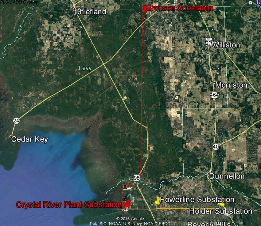
Appendix A1
REBUILD Transmission Line 230kV from Crystal River Plant to Bronson Substation. Single Circuit.
Use of the existing route.
Legend: red = existing Line to be rebuild
Shady Hills (Q137) Facilities Study Date: December 1, 2016
Page 21 of 24Facilities Study Report
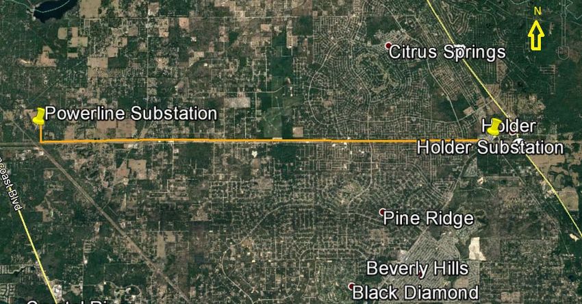
Appendix A2
NEW Transmission Line 230kV from Holder to Powerline Substation. Single Circuit.
Proposed route.
Legend: orange=new line
Shady Hills (Q137) Facilities Study Date: December 1, 2016
Page 22 of 24Facilities Study Report
Appendix A3
Proposed 230kV Hudson North Substation
Shady Hills (Q137) Facilities Study Date: December 1, 2016
Page 23 of 24You can also read