Enphase Enpower Smart Switch - INSTALLATION AND OPERATION MANUAL
←
→
Page content transcription
If your browser does not render page correctly, please read the page content below
INSTALLATION AND OPERATION MANUAL

Enphase Enpower Smart Switch

 August 5, 2020                     141-00046-01
Enpower smart switch installation and operation

Corporate Headquarters Contact Information

enphase.com/en-us/support/contact

Other Information
Product information is subject to change without notice. All trademarks are recognized as the property of
their respective owners.

User documentation is updated frequently; Check the Enphase website (enphase.com/support) for the
latest information.

To ensure optimal reliability and to meet warranty requirements, the Enphase Microinverter must be
installed according to the instructions in this manual. For warranty text refer to enphase.com/warranty.

For Enphase patent information refer to enphase.com/company/patents/.

© 2020 Enphase Energy Inc. All rights reserved. Enphase, the Enphase logo, Enpower, Encharge, IQ
Envoy, IQ Combiner, IQ Microinverter, Installer Toolkit, Enlighten and other trademarks or service names
are the trademarks of Enphase Energy, Inc. Data subject to change.

Audience
This manual is intended for use by professional installation and maintenance personnel.

            NOTE: To ensure optimal reliability and to meet warranty requirements, the Enphase
            Enpower must be installed according to the instructions in this manual.

Environmental Protection
         ELECTRONIC DEVICE: DO NOT THROW AWAY. Waste electrical products should not be
         disposed of with household waste. Refer to your local codes for disposal requirements.

2                             © 2020 Enphase Energy Inc. All rights reserved.                      141-00046-01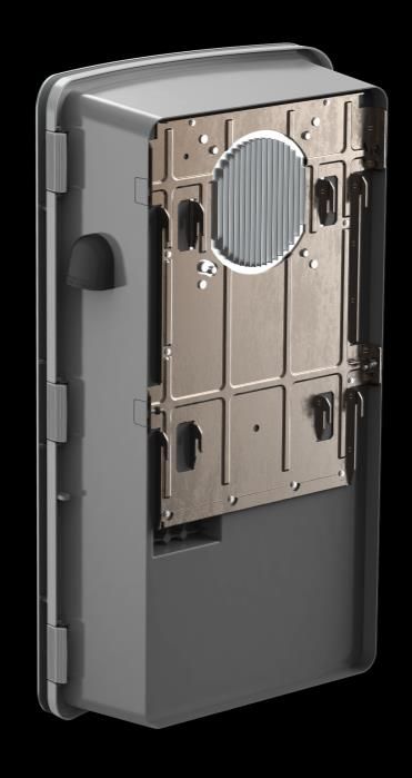
Enpower smart switch installation and operation

Table of Contents
Important Safety Information ..........................................................................................................................................4
        Read this First..................................................................................................................................................4
        Safety and Advisory Symbols ..........................................................................................................................4
        Enpower Smart Switch Safety Instructions ......................................................................................................4

The Enphase Ensemble System ....................................................................................................................................6

The Enpower Smart Switch ............................................................................................................................................7
       Installation Scenarios .......................................................................................................................................7

Enpower Installation Preparation and Requirements .....................................................................................................9
       Preparation ......................................................................................................................................................9
       Use the Enphase Installer Toolkit .................................................................................................................. 10

Enphase Enpower Installation ...................................................................................................................................... 11
       Step 1: Plan a Location for the Enpower........................................................................................................ 11
       Step 2: Install the Wall-Mount Bracket ........................................................................................................... 12
       Step 3: Unbox and Mount the Enpower on the Wall ...................................................................................... 13
       Step 4: Install Breakers as Needed ............................................................................................................... 14
       Step 5: Wire the Field Connections ............................................................................................................... 17
       Step 6: Close and Energize Enpower ............................................................................................................ 20
       Field Adjustable Trip Points ........................................................................................................................... 20
       Configure and Activate................................................................................................................................... 20

Troubleshooting ........................................................................................................................................................... 21
        Enpower Manual Override Switch .................................................................................................................. 21
          Manual Override for Enpower .................................................................................................................... 22
          Initiating Manual Override (Tied to Grid) .................................................................................................... 22
          Exiting Manual Override ............................................................................................................................ 23

Specifications ............................................................................................................................................................... 24

3                                                © 2020 Enphase Energy Inc. All rights reserved.                                                              141-00046-01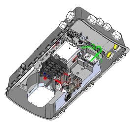
Enpower smart switch installation and operation

Important Safety Information
Read this First
This manual describes the safe installation and operation of the Enphase Enpower™ smart switch.

Safety and Advisory Symbols
To reduce the risk of electric shock, and to ensure the safe installation and operation of the Enphase IQ
System, the following safety symbols appear throughout this document to indicate dangerous conditions
and important safety instructions.
           DANGER: This indicates a hazardous situation, which if not avoided, will result in death or serious
           injury.

           WARNING: This indicates a situation where failure to follow instructions may be a safety hazard or
           cause equipment malfunction. Use extreme caution and follow instructions carefully.

    ✓
           NOTE: This indicates information particularly important for optimal system operation. Follow instructions
           carefully.

Enpower Smart Switch Safety Instructions
           DANGER: Risk of electric shock. Risk of fire. Only qualified electricians should install, troubleshoot, or
           replace the Enpower.

           DANGER: Risk of electric shock. Risk of fire. Do not attempt to repair the Enpower. Tampering with or
           opening the Enpower will void the warranty. If the Enpower fails, contact Enphase Customer Support for
           assistance at enphase.com/en-us/support/contact.

           DANGER: Risk of electric shock. Do not use Enphase equipment in a manner not specified by the
           manufacturer. Doing so may cause death or injury to persons, or damage to equipment.

           DANGER: Risk of electric shock. Do not install the Enpower without first removing AC power from the
           photovoltaic system and ensuring that the DC switch on the Enphase Encharge batteries are off.
           Disconnect the power coming from the photovoltaics and ensure that the DC switch on the Encharge
           batteries are off before servicing or installing.
           DANGER: Risk of electric shock. Risk of fire. Do not work alone. Someone should be in the range of
           your voice or close enough to come to your aid when you work with or near electrical equipment.

           DANGER: Risk of fire. Do not allow or place flammable, sparking, or explosive items near the Enpower.
           DANGER: Risk of electric shock. In areas where flooding is possible, install the Enpower at a height that
           prevents water ingress.

           WARNING: Risk of equipment damage. Enpower is shipped and stored on its back. The upright position
           is only needed when installed.

           WARNING: You must install the Enpower only on a suitable wall using an Enphase wall-mount bracket.
           WARNING: Before installing or using the Enpower, read all instructions and cautionary markings in this
           guide and on the equipment.

           WARNING: Do not install or use the Enpower if it has been damaged in any way.
           WARNING: Do not sit on, step on, place objects on, or insert objects into the Enpower.
           WARNING: Do not place beverages or liquid containers on top of the Enpower. Do not expose the
           Enpower to liquids or flooding.

4                              © 2020 Enphase Energy Inc. All rights reserved.                             141-00046-01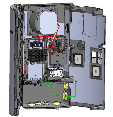
Enpower smart switch installation and operation

    ✓
        NOTE: Perform installation and wiring, including protection against lightning and resulting voltage surge,
        in accordance with all applicable local electrical codes and standards.
        NOTE: Because Encharge is grid forming, you must install signage in accordance with NEC articles 705,
        706, and 710.
        NOTE: Using unapproved attachments or accessories could result in damage or injury.
        NOTE: Install properly rated over current protection as part of the system installation.
        NOTE: To ensure optimal reliability and to meet warranty requirements, the Enpower must be installed
        and/or stored according to the instructions in this guide.
        NOTE: The Enpower is compatible only with the IQ Envoy communications gateway properly fitted with
        USB hub, USB radios, and production and consumption CTs. The IQ Envoy is required for operation of
        the Enpower. Earlier versions of the Enphase Envoy communications gateway are incompatible.
        NOTE: The Enphase Enpower is intended to operate with an Internet connection through the Envoy.
        Failure to maintain an Internet connection may have an impact on the warranty. See Limited Warranty
        for full terms and services (enphase.com/warranty).
        NOTE: Properly mount the Enpower. Ensure that the mounting location is structurally suited to bearing
        the weight of the Enpower.
        NOTE: During use, storage, and transport, keep the Enpower:
             •     Properly ventilated
             •     Away from water, other liquids, heat, sparks, and direct sunlight
             •     Away from excessive dust, corrosive and explosive gases, and oil smoke
             •     Away from direct exposure to gas exhaust, such as from motor vehicles
             •     Away from falling or moving objects, including motor vehicles. If mounted in the path of a motor
                   vehicle, we recommend a 91cm (36-inch) minimum mounting height
             •     In a location compliant with fire safety regulations
             • In a location compliant with local building codes and standards
        NOTE: While Enpower provides capability for connection of a generator, it does not presently support
    1   use with generators. Do not attempt to connect a generator until Enpower is ready to support a
        generator. This functionality is reserved for future use and will require an upgrade process to be followed
        by a qualified electrician.
        NOTE: Enpower is not suitable for use as service equipment in Canada.
    2

5                           © 2020 Enphase Energy Inc. All rights reserved.                           141-00046-01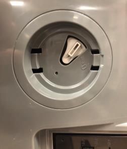
Enpower smart switch installation and operation

The Enphase Ensemble System
With the Enphase Ensemble™ energy management technology, homeowners have power when the grid
goes down and save money when the grid is up. The system measures PV production, home energy
consumption, and energy storage. The system knows when it is optimal to charge or discharge battery
power so that energy is stored when it is abundant and used when scarce. Ensemble technology systems
include the following Enphase products:

    1. Enphase Enpower™ smart switch connects the home to grid power, the Encharge storage
       system, and solar PV. It provides microgrid interconnection device (MID) functionality by
       automatically detecting and seamlessly transitioning the home energy system from grid power to
       backup power in the event of a grid failure. It consolidates interconnection equipment into a single
       enclosure and streamlines grid independent capabilities of PV and storage.
    2. Enphase Encharge™ storage system is reliable, simple, and safe. It provides backup capability
       and installers can quickly design the right system size to meet the needs of both new and retrofit
       solar customers.
    3. IQ™ combiner series consolidates interconnection equipment and streamlines PV and storage
       installations by providing a consistent, pre-wired solution for residential applications. Housed in
       the combiner is an Enphase IQ Envoy™, a communication device that provides network access
       to the PV array. The IQ Envoy collects production and performance data from the Ensemble
       system over on-site AC power lines and transmits the data to Enlighten through an Internet or
       cellular modem connection.
    4. Enphase IQ™ Series microinverters. The smart grid ready IQ Series microinverters convert
       harvested solar power into usable energy.
    5. Enphase Enlighten™ web-based monitoring and management software. Installers can use
       Enlighten Manager to view detailed performance data, manage multiple PV systems, and
       remotely resolve issues that might impact system performance. Find out more at
       enphase.com/enlighten.

6                            © 2020 Enphase Energy Inc. All rights reserved.                      141-00046-01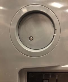
Enpower smart switch installation and operation
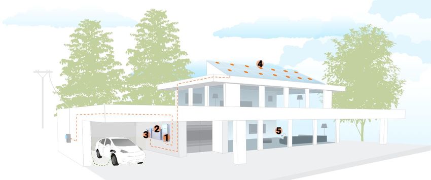
The Enpower Smart Switch
The Enphase Ensemble System includes the Enphase Enpower™ smart switch with Microgrid
Interconnection Device (MID) capability, which consolidates interconnection equipment into a single
enclosure and streamlines grid-independent capabilities of PV and storage installations by providing a
consistent, pre-wired solution for residential applications. Along with MID functions, it includes PV,
storage, and generator (reserved for future use¹) input circuits.
To install the Enphase Enpower™ smart switch and the Enphase Enpower wall-mount bracket, read and
follow all warnings and instructions in this manual. These instructions are not meant to be a complete
explanation of how to design and install an energy storage system. All installations must comply with
national and local electrical codes and standards. Only qualified electricians shall install, troubleshoot, or
replace the Enpower.
Installation Scenarios
Four unique installation scenarios are shown in the following:
• Whole home backup with Enpower as service entrance and PV combiner connected to
Enpower. This is the preferred configuration for back up of the entire main load panel. This
configuration supports up to an 80A breaker for the PV circuit and an 80A breaker for battery storage.
Generator
(reserved for future use¹)
7 © 2020 Enphase Energy Inc. All rights reserved. 141-00046-01
Enpower smart switch installation and operation

•   Whole home backup with Enpower as service entrance and PV combiner connected to main
    load panel. This is the preferred configuration when you back up the entire main load panel, and the
    size of the PV combiner circuit is more than 80A. In this configuration, the PV combiner circuit
    connection space in Enpower is left vacant. When existing PV combiner circuits are connected to the
    main load panel, and you want to add battery storage to the system, you can keep the PV combiner
    connected to the main load panel and connect only the battery storage system to Enpower.

                                                                          Generator
                                                                          (reserved for future use¹)

•   Partial home backup with main load panel as service entrance and PV combiner connected to
    Enpower. When PV circuits breaker size is less than 80A, this is the preferred configuration for
    partial home backup with subpanel.

                                                                           Generator
                                                                         (reserved for
                                                                          future use¹)

8                            © 2020 Enphase Energy Inc. All rights reserved.                           141-00046-01
Enpower smart switch installation and operation
• Partial home backup with main load panel as service entrance and PV combiner connected to
sub-panel. This is the preferred connection configuration for partial home backup using a subpanel
when the PV circuit breaker size is more than 80A. The space available in Enpower for combiner
(solar) connection is left vacant.
Generator
(reserved for
future use¹)
Enpower Installation Preparation and Requirements
Preparation
1. Inspect the packaging and the Enpower for damage. Do not install or use the Enpower if it has been
damaged in any way.
2. Ensure that you have the following:
• One Enphase Enpower smart switch. The Enpower shipping box contains an Enphase Enpower,
mounting bracket, mounting hardware, and lit kit (bag with labels and accessories). Among the
accessories are four-pin receptacles/dry contacts that will be used for controlling external power
relays in future and are not needed at present.
WARNING: The Enpower smart switch weighs 38.5 kg (85 lbs) and will require two
persons to lift the unit.
• An Enphase Enpower literature kit (150-00148)
3. Make sure you have the following required items:
• Enphase Encharge™ storage system, which is required for off-grid applications.
• The Enphase Enpower requires a wireless connection to an IQ Envoy, which requires an Internet
connection. Failure to maintain an Internet connection may have an impact on the warranty. See
enphase.com/warranty for full terms and services.
• Wireless USB Adapter (COMMS-KIT-01) to be installed at Envoy for communications with
Encharge and Enpower. Includes USB cable for connection to IQ Envoy / IQ Combiner and
allows wireless communication with Encharge and Enpower.
• Enpower lifting handles (EP200G-HNDL-R1).
9 © 2020 Enphase Energy Inc. All rights reserved. 141-00046-01Enpower smart switch installation and operation
• Eaton BR Series breakers, rated maximum 80A for Encharge storage system and Enphase IQ™
combiner.
• If breakers are required at the input or output to Enpower, use Eaton, Type CSR breakers rated
100 A, 125 A, 150 A, 175 A or 200 A.
• Tools: conduit (with fittings and fitting tools), drill, 5/32 inch pilot bit (or metric equivalent),
screwdriver, socket, wrench, adjustable wrench, torque wrench, level, 5/32 inch Allen key (or
metric equivalent), conductor stripper, electrician’s hole saw (2 inch) kit or punch set, and stud
finder, if installing on studs.
• Conduit fittings (hubs) are required for all installations, and NEMA Type 3 conduit fittings (hubs)
are needed when installing out of doors (one for each used conduit opening).
• Conduit ground hub rings.
NOTE: Conduit entry is allowed only through the bottom or bottom sides of the unit.
• Three #10, 1/4”, or 5/16” lag bolts or screws, 7.6cm (3 inches) long (depending on attachment
wall), for each wall-mount bracket. Check with a structural engineer and local standards for local
requirements.
• Washers for use between fastener heads and wall-mount bracket.
• Conductors rated at 75°C. For sizes, refer to the table on the unit and to local codes.
• Over current protection: maximum in accordance with local standards.
• The door sheet metal is not required to be grounded, since it is protected from live parts by other
grounded metal and insulating plastic materials, thus is considered unlikely to become energized.
NOTE: Protection against lightning and resulting voltage surge must be in accordance with
local standards.
Use the Enphase Installer Toolkit
Enphase Installer Toolkit™ mobile app for iOS and Android devices. It allows installers to
configure the system while onsite, eliminating the need for a laptop and improving installation
efficiency. You can use the app to:
• Connect to the IQ Envoy over a wireless network for faster system setup and verification
• View and email a summary report that confirms a successful installation
• Scan device serial numbers and sync system information with Enlighten monitoring software
10 © 2020 Enphase Energy Inc. All rights reserved. 141-00046-01Enpower smart switch installation and operation
Enphase Enpower Installation
Installing the Enphase Enpower smart switch involves several key steps. Each step listed here is detailed
in the following pages.
Step 1: Plan a Location for the Enpower
Step 2: Install the Wall-Mount Bracket
Step 3: Unbox and Mount the Enpower on the Wall
Step 4: Install Breakers as Needed
Step 5: Wire the Field Connections
Step 6: Close and Energize Enpower
Step 1: Plan a Location for the Enpower
The Enpower housing is NEMA type 3R and can be installed indoors or outdoors.
A. Follow all local codes and standards when planning for and installing the Enphase Enpower
Smart Switch.
B. Choose a well-ventilated location where the ambient temperature is within -40° C to 50° C (-40° F
to 122° F), preferably out of direct sunlight.
C. Ensure that the mounting location can sustain the weight of the Enpower and mounting bracket
38.5 kg (85 lbs). The wall must include studs that can bear 38.5 kg (85 lbs) or can be of masonry
or other suitable structure that can bear the weight.
D. Plan the mounting location:
• Indoors: at least 15cm (six inches) off the ground and 15cm (six inches) from the ceiling.
• Outdoors: at least 91cm (three feet) off the ground.
E. Ensure that there are no pipes or electrical conductors where you plan to drill.
F. Plan to maintain at least 90cm (three feet) of clearance in front of the Enpower.
G. Consider the dimensions of the Enpower, easy access, unit height, conduit entry, and length of
cable when selecting the location.
H. Select a location where you can interconnect to the site’s load center using the Enphase
Enpower.
11 © 2020 Enphase Energy Inc. All rights reserved. 141-00046-01Enpower smart switch installation and operation
Step 2: Install the Wall-Mount Bracket
A. Mark a plumb line over the wall stud as a guide.
WARNING! Multiple risks. Make sure not to drill or attach into electric wiring or pipes that are
in the wall!
B. Remove the wall mount bracket only from the shipping box.
C. Place the wall-mount bracket on the wall so that the mounting holes in the middle of the bracket
align with the center of the stud. Use a level to keep the bottom of the wall-mount bracket level.
D. Use the #10, 1/4”, or 5/16” wood screws (or masonry attachments if installing in masonry) to
attach the bracket using one screw and washer for each slot. The slot size of the Enpower wall
mount bracket is 8.5 mm. Use an appropriately sized washer for each of the screws, and check
with a structural engineer and local standards for local requirements.
E. Verify that the wall-mount bracket is level, solidly attached to the wall, and oriented for upright
installation of the Enpower.
WARNING! Risk of injury and equipment damage. Do not mount an Enpower on a bracket
that is not properly attached to a wall.
WARNING! Risk of injury and equipment damage. Protect the Enpower from impact damage
and improper use.
12 © 2020 Enphase Energy Inc. All rights reserved. 141-00046-01Enpower smart switch installation and operation
Step 3: Unbox and Mount the Enpower on the Wall
WARNING: Risk of injury. Take care when lifting. The Enpower is heavy 38.5 kg (85 lbs).
WARNING! Risk of injury and equipment damage. Avoid dropping the Enpower. Doing so
may create a hazard, cause serious injury, and/or damage the equipment.
A. Remove the lid from the Enpower box, and locate the slots on both sides of the Enpower
enclosure.
B. Locate the lifting handles (sold separately) and check
that the plungers are extended and ready to engage
into the Enpower slots.
C. Align one handle on one side of the Enpower and
press the handle into the slots, and slide the handle
toward the top of the Enpower enclosure until it clicks
into place. Check that the handle is secure.
D. Repeat on the other side with the second handle.
WARNING! Risk of injury and equipment
damage. Two persons are required to lift the
Enpower.
E. Use the lifting handles, take the Enpower from the packaging, making sure it is top side up
(upright). Enpower is designed only for vertical installation without inclination (must be level).
F. Lift the Enpower slightly above the installed wall mount bracket and allow it to slide down so that
the bracket facing hooks set into both the top and bottom shelves of the wall mount bracket.
G. Allow the Enpower to slide down until the Enpower is fully seated on the wall-mount bracket shelf.
WARNING! Risk of injury and equipment damage. Do not
release the Enpower until you ensure that the Enpower is fully
seated in the wall-mount bracket shelf.
H. For each handle, pull the plunger tabs to release them and remove
the lift handles.
I. Reserve the handles for the next installation.
J. On the bottom handle mounts, use the two provided partial-
threaded custom M6 screws to secure each side of the Enpower
and tighten to 0.5 N•m (4.4 lb•in) or less.
The threaded portion of the screw engages with the bracket, while
the unthreaded portion of the screw engages with the hole in the
bracket to prevent vertical movement of the bracket.
WARNING! Risk of injury and equipment damage. Do not skip
this step. Without these screws in place, the Enpower may fall
and cause injury or damage if bumped or shaken.
K. Use the four filler plates, provided in the lit kit,
to cover the screws.
Bracket facing hooks on
rear of Enpower
13 © 2020 Enphase Energy Inc. All rights reserved. 141-00046-01Enpower smart switch installation and operation
Step 4: Install Breakers as Needed
The Enpower includes one two-pole 40A circuit breaker that feeds the neutral forming transformer (NFT).
You can install additional breakers, if needed. You must follow all NEC and local electrical codes.
Install breakers as needed for the AC grid, main load, Enphase IQ Combiner, Enphase Encharge
batteries, and generator (reserved for future use¹). These breakers are not included and must be ordered
separately.
NOTE: You must install a backup loads breaker if required by local code.
NOTE: Generator connection is not currently supported. This feature will be supported in
future after an over-the-air software upgrade.
WARNING! Risk of injury and equipment damage. Use only the breakers listed in the
following table.
Allowed breaker types include:
Enphase Model No. Type and Eaton part no.
BRK-100A-2P-240V • Main Breaker, 2 pole, 100A, 25kAIC, CSR2100
BRK-125A-2P-240V • Main Breaker, 2 pole, 125A, 25kAIC, CSR2125N
BRK-150A-2P-240V • Main Breaker, 2 pole, 150A, 25kAIC, CSR2150N
BRK-175A-2P-240V • Main Breaker, 2 pole, 175A, 25kAIC, CSR2175N
BRK-200A-2P-240V • Main Breaker, 2 pole, 200A, 25kAIC, CSR2200N
BRK-20A-2P-240V-B • Circuit Breaker, 2 pole, 20A, 10kAIC, BR220B
BRK-30A-2P-240V • Circuit Breaker, 2 pole, 30A, 10kAIC, BR230B
BRK-40A-2P-240V • Circuit Breaker, 2 pole, 40A, 10kAIC, BR240B
BRK-60A-2P-240V • Circuit Breaker, 2 pole, 60A, 10kAIC, BR260
BRK-80A-2P-240V • Circuit Breaker, 2 pole, 80A, 10kAIC, BR280
Breaker installation positions are noted in the diagram: Enpower breaker positions
A. Ensure that the Enpower is completely de-energized.
B. Open the three latches that lock the enclosure door.
To release the latch, pull the latch handle forward and
then to the right. With all the latches opened, swing
open the enclosure door.
WARNING: Risk of equipment damage. Do not
remove the pre-installed solar shield attached to
the enclosure door.
C. Use a Phillips screw driver to loosen the six screws
along the periphery of the deadfront. Support the
deadfront to keep it from falling while performing the
next step
14 © 2020 Enphase Energy Inc. All rights reserved. 141-00046-01Enpower smart switch installation and operation
D. While supporting the deadfront, use a
screwdriver to disconnect the deadfront
ground wire from the grounding bar before the
deadfront is removed.
E. Use the two tabs on the front to assist
handling the deadfront during the removal.
Keep the deadfront and screws handy as you
will need them later.
WARNING: Risk of electric shock. To
maintain the warranty, do not modify the
deadfront other than to remove or replace
filler plates, as needed.
F. If you install a main breaker or load breaker,
remove the standard lugs before installing the
Eaton CSR breaker. By default, lugs are
provided in the Enpower unit for connection to
the mains and to the load. In case of usage
without breakers, the conductors are
connected directly to these lugs. When
breakers are used, the lugs are replaced with
breakers during installation.
G. Remove a filler plate from the deadfront for each breaker position you will use. Refer to the
breaker position diagram. To remove the filler plate, press the two snaps inward while gently
pushing the filler plate out.
H. For the Encharge, AC Combiner or Generator (reserved for future use¹) connection, snap the
appropriately sized BR series two-pole Eaton breaker onto the busbar, using only the breaker
positions indicated in the diagram on the door of the unit. Breaker functional position are not
interchangeable with one another. The wires to be connected to each breaker are located beside
each breaker position. Remove the heatshrink cap on wire ends before inserting into the breaker.
I. Install each breaker by rocking it to the left, catching the clips that hold it in place. Then rock the
breaker to the right so it is fully seated and secure.
J. For the main load breaker, use an appropriately sized CSR Eaton breaker. Install at the location
indicated in the
diagram on the
door of the unit. Install M4
screw here
K. Remove the
mains/load lugs by
unscrewing (use a
1/4” hex drive) the
two nuts holding
the lugs. Re-use
the same nuts to
fix the CSR
breakers in the
same position.
Torque to 4 N•m
(35.4 lb•in). Lugs at main load breaker position Breakers installed at main load position
L. Use the M4 screw
(from the lit kit marked 150-00148 that ships with the Enpower) to secure the mains breaker (not
the load breaker). Use a T20 drive to tighten the M4 screw to 1.5 N•m (13.3 lb•in). Do not use any
other screw.
15 © 2020 Enphase Energy Inc. All rights reserved. 141-00046-01Enpower smart switch installation and operation
M. Check that all breakers are properly seated.
N. Torque the breaker connections as listed in the following and in the conductor table on the unit.
O. Purchase and install an Eaton type BR circuit breaker hold-down screw kit (model BRHDK125) to
secure only the Encharge and generator (reserved for future use¹) double-pole circuit breaker(s).
Refer to https://www.homedepot.com/p/Eaton-Type-BR-Hold-Down-Bolting-Screw-Kit-
BRHDK125/100193360 for installation information and specifications.
Connections Wire size (AWG) Torque (N-m / lb-in)
Main lugs, Backup load lugs (use a 1/4” hex drive) Cu/AL: 300 KCMIL - 1 31.1 / 275
CSR breakers Cu/AL: 300 KCMIL - 2 28.2 / 250
BR breakers (wire provided) 6 3.1 / 27
AC Combiner lugs, 14 - 10 2.8 / 25
Encharge lugs, and 8 3.4 / 30
Generator (reserved for future use¹) lugs 4-6 3.9 / 35
2-3 4.5 / 40
Neutral - large lugs (use a 3/8” hex drive) Cu/AL: 300 KCMIL - 6 31.1 / 275
Neutral and ground bars
Large holes (5/16-24 UNF) 1/0 - 3 5.6 / 50
4-6 5.1 / 45
8 4.5 / 40
10 -14 4.0 / 35
Small holes (10-32 UNF) 6-8 2.8 / 25
10 -14 1.7 / 15
Required practices when securing wires within the lugs:
• For the main/load lugs, use a 1/4” hex drive.
• For the neutral lugs, use a 3/8” hex drive.
Main/load lug Neutral lug
Required practices when torquing connections:
• Always follow NEC 2017 110.4 (D) dictates.
• You must use a calibrated torque tool to achieve the indicated torque values.
• Use tamper-proof torque mark/paint after torquing connections.
16 © 2020 Enphase Energy Inc. All rights reserved. 141-00046-01Enpower smart switch installation and operation
Step 5: Wire the Field Connections
A. Drill conduit entry holes as needed, and install conduit grounding lugs for each opening. Be sure
to reseal unused conduit entry holes with sealing plugs.
NOTE: Main supply
conductors may enter the
Enpower from the bottom or
from the bottom-left side.
Backup load conductors
may enter the Enpower from
the bottom or bottom-right
side. Encharge, Combiner
and generator (reserved for
future use¹) conductors may
enter from the bottom,
bottom-left or bottom-right
sides.
B. Size the conductors (Line,
Neutral and Ground) depending
on the breaker or fuse, proper
ampacity, and voltage rise
requirements according to local
codes. Refer to the conductor
rating table on the door of the
Enpower.
DANGER! Risk of electric shock. Check that all circuits connecting to the Enpower are de-
energized before wiring.
C. If the Enpower is not installed as service equipment2, you must remove the main bonding jumper
connected between the grounding bar and the neutral assembly. Refer to the wiring diagram.
NOTE: Do not modify or rewire any of the other pre-installed wiring or bonding connections in
the Enpower.
D. If Enpower is installed as service equipment2:
• Connect a grounding electrode conductor to the grounding bar.
• From the lit kit, place the label “GROUNDING ELECTRODE TERMINAL” adjacent to
the grounding bar.
• From the lit kit, place the label “SUITABLE FOR USE AS SERVICE EQUIPMENT” /
“MAIN SERVICE DISCONNECT” on the deadfront near the main breaker/service
disconnect.
• If Enpower is not used as service equipment, these labels should not be used.
E. Connect Lines, Neutral, and Ground. For details, refer to the conductor table on the unit for sizes
and refer to local codes.
WARNING! Risk of equipment damage. Always connect to two Lines (active), one neutral,
and one ground.
17 © 2020 Enphase Energy Inc. All rights reserved. 141-00046-01Enpower smart switch installation and operation
F. Use the included stowed conductors, as labeled, to wire the circuit breaker(s) for the Encharge
batteries, Enphase Combiner, and generator (reserved for future use¹) as needed. The stowed
conductors are provided with crimped-on ferrules with end caps to prevent accidental contact.
Remove the conductor end caps as needed.
G. Torque the breaker connections as listed on the previous page and in the conductor table on the
unit.
H. After all conductors are connected and secured, check that there are no exposed conductors or
stray wires.
I. Gently arrange all the conductors and connectors inside the cabinet.
DANGER! Risk of electric shock. The system is not ready to be energized! Do not close any
circuit breaker yet.
NOTE: The polarity of L1 and L2 is swapped inside Eaton CSR series main breakers.
Installers should follow L1 and L2 on the following image when installing consumption CTs.
Reserved for
future use
Reserved for
future use
18 © 2020 Enphase Energy Inc. All rights reserved. 141-00046-01Enpower smart switch installation and operation 19 © 2020 Enphase Energy Inc. All rights reserved. 141-00046-01
Enpower smart switch installation and operation

Step 6: Close and Energize Enpower
           WARNING: Before energizing, make sure that ALL Enpower connections are properly
           installed and conductors terminated.

       A. Reconnect the deadfront ground cable to the grounding bar, torque as shown in the table on
          the unit label (and in Step 4 of this guide), and replace the deadfront using the six reserved
          screws. Tighten the cover screws using a Phillips screw driver.

           WARNING! Risk of equipment damage. Ensure that no conductors are pinched before
           replacing the cover.

           WARNING! Conductors are factory provided for the generator (reserved for future use¹), AC
           Combiner and Encharge. If no generator is used with the system, these conductors will not
           be terminated. If the Combiner does not connect to the Enpower, these also will not be
           terminated. When these wires are not terminated, they should remain stowed in the clips on
           the plastic frame supporting the panel board interior and their end caps should not be
           removed.

           DANGER: Risk of electric shock. There are many potential sources of voltage. Check any
           Enphase Encharge battery, PV, or other generation source for voltage.

       B. You must ensure that all electrical circuits external to Enpower are completed and safe
          before energizing Enpower.
       C. If you plan to energize Enpower without commissioning the system in the same day, OPEN
          the NFT and Encharge breakers and CLOSE the other breakers in the following order:
          ▪ Main breaker
          ▪ PV breaker
          ▪ Generator (reserved for future use¹) breaker
          ▪ Load breaker
       D. If you plan to commission the system, follow the instructions in ITK (Installer Toolkit) for
          energizing Enpower.
       E. Energize the circuit feeding the Enpower. If installed, turn the breaker feeding the Enpower to
          the on position.
       F. Close and secure the door of the Enpower.

Field Adjustable Trip Points
Enpower has field-adjustable voltage and frequency trip points that may need to be set, depending upon
local requirements. Only an authorized installer with the permission and following requirements of the
local electrical authorities should make adjustments.

Configure and Activate
Use the Enphase Installer Toolkit to commission the Enpower. Once connected to the Envoy, refer to the
Installer Toolkit help topics for more information.

20                           © 2020 Enphase Energy Inc. All rights reserved.                      141-00046-01
Enpower smart switch installation and operation
Troubleshooting
Follow all the safety measures described throughout this manual. Qualified personnel can use the
following basic troubleshooting steps if the system does not operate correctly.
For detailed Troubleshooting information, see the Enphase Technical Brief: Troubleshooting an
Enphase Ensemble Energy Management Technology System.
Enpower Manual Override Switch
WARNING: Risk of electric shock. Do not remove the override switch cover or use the
override switch unless directed to do so by Enphase Customer Support. Contact
enphase.com/en-us/support/contact for help.
In the case that the system is failed with the MID in the opened position, it may be necessary to place the
Enpower MID relay into manual bypass mode until the equipment can be serviced.
Prior to actuating the Enpower override switch, all power sources feeding the Enpower must be
deenergized. The main breaker feeding Enpower must be shut off. Also, shut of the Encharge battery
circuit breaker and the IQ Combiner circuit breaker in Enpower.
Access the manual override switch under the removable cover on the Enpower deadfront (only remove
the cover and label after the system is commissioned). To access the override switch:
A. Remove the label.
B. Remove the screw using a manual #1 Phillips manual screw driver. Torque
to remove ~0.5 N m (4.4 in-lbs). Make sure the screwdriver does not slip
and damage the screw.
C. Remove the plastics snaps.
5.3 mm screw
In close up of the Enpower override switch, the switch is in
the normal position.
To manually place the override
switch into bypass mode, move the
white switch to the left.
To manually place the override
switch back into normal operation
mode, move the white switch to the
right.
Screw to remove
Turn the main breaker and
Enpower breakers back on when
service is complete.
Switch
21 © 2020 Enphase Energy Inc. All rights reserved. 141-00046-01Enpower smart switch installation and operation
Manual Override for Enpower
Manual override is a feature of Enpower for Enphase Ensemble systems. The intent of this feature is to
allow the system to go to the grid-tied mode, when you are instructed to do so by Enphase customer
support. You may be instructed to use the function if there is a malfunction in the Enpower main relay or
other components of the system that prevents the automatic operation of the main relay in Enpower.
There are two possible connection states of an Ensemble system to the grid in Enpower: connected
(grid-tied) or disconnected. Connection of the system to the grid is automatically controlled by Enpower.
In case of an Ensemble system failure to connect to the grid either automatically or via a command sent
by its control system, you can use the manual override function in Enpower to force a connection to the
grid. Use the manual override function only when instructed by Enphase customer support.
NOTE: Do not use the manual override function to arbitrarily disconnect the system from
the grid. If you want to disconnect from the grid manually, the mains breaker in the main
load panel or the main breaker in Enpower may be used.
Initiating Manual Override (Tied to Grid)
Refer to the wiring diagram in Step 5: Wire the Field Connections when performing this procedure. In the
event the Ensemble system malfunctions and causes the home to lose power without an actual grid
outage, you (after receiving instruction from Enphase customer support) can perform the manual override
by following these steps:
1. OPEN the following breakers in sequence:
a. Encharge breaker inside Enpower
b. Mains breaker powering the Enpower from the grid side. (This main breaker could be the
main breaker inside Enpower, installed in certain configurations, or the main breaker that
powers the Enpower from the grid side, which may be located outside the Enpower or inside
the main load center of the site.)
c. Auto transformer breaker inside Enpower
NOTE: No need to open PV combiner breaker and load side breaker inside Enpower.
2. Turn OFF all Encharge units by turning OFF the DC switches on each Encharge base unit.
3. Wait for at least 60 seconds for all residual charge on the control boards to be discharged.
4. Remove the patch from the Manual Override section of the Enpower to make the small manual
override toggle visible.
5. Turn the toggle to the left to manually CLOSE the MID relay.
6. Turn ON the mains breaker. If load side breaker or PV combiner breaker in Enpower were opened
earlier, they can be closed now.
The system should now be in manual override mode and grid tied. The home will remain connected to
grid like a grid-tied PV only system.
22 © 2020 Enphase Energy Inc. All rights reserved. 141-00046-01Enpower smart switch installation and operation
Exiting Manual Override
Because of the criticality of an event that may lead to a manual override, care has been taken to ensure
that the system does not randomly come out of this state, unless explicitly forced to exit. The manual
override state is immune to power cycles, resets, reset glitches, etc. A service visit to the site might be
needed perform the exit from manual override.
To exit manual override on site, perform the following steps:
1. OPEN the following breakers in sequence:
a. Encharge breaker inside Enpower
b. Mains breaker powering the Enpower from the grid side (this could be inside or outside the
Enpower unit)
c. Auto transformer breaker inside Enpower
NOTE: No need to open PV combiner breaker and load side breaker inside Enpower.
2. Turn OFF all Encharge units by turning OFF their DC switches.
3. Wait for at least 60 seconds for all residual charge on the control boards to get discharged.
4. Turn the manual override toggle inside the Enpower to the right to manually OPEN the MID relay.
5. CLOSE all the breakers in sequence:
a. NFT breaker inside the Enpower
b. Mains breaker
c. Encharge breaker inside the Enpower
6. Turn ON all Encharge units by turning ON the DC switches.
NOTE: If Load Side breaker or PV combiner breakers were OPEN inside Enpower, they
can be CLOSED now.
The Enpower system is now no longer in manual override state and is fully functional.
23 © 2020 Enphase Energy Inc. All rights reserved. 141-00046-01Enpower smart switch installation and operation
Specifications
MODEL NUMBER
EP200G101-M240US00 Enphase Enpower smart switch with neutral-forming transformer (NFT),
Microgrid Interconnect Device (MID), breakers, and screws. Streamlines grid-
independent capabilities of PV and storage installations.
ACCESSORIES and REPLACEMENT PARTS
XA-E3-PCBA-ENS Replacement Enpower controller printed circuit board
Circuit breakers (as needed)A,B Not included, must be ordered separately:
BRK-100A-2P-240V • Main Breaker, 2 pole, 100A, 25kAIC, CSR2100
BRK-125A-2P-240V • Main Breaker, 2 pole, 125A, 25kAIC, CSR2125N
BRK-150A-2P-240V • Main Breaker, 2 pole, 150A, 25kAIC, CSR2150N
BRK-175A-2P-240V • Main Breaker, 2 pole, 175A, 25kAIC, CSR2175N
BRK-200A-2P-240V • Main Breaker, 2 pole, 200A, 25kAIC, CSR2200N
BRK-20A-2P-240V-B • Circuit Breaker, 2 pole, 20A, 10kAIC, BR220B
BRK-30A-2P-240V • Circuit Breaker, 2 pole, 30A, 10kAIC, BR230B
BRK-40A-2P-240V • Circuit Breaker, 2 pole, 40A, 10kAIC, BR240B
BRK-60A-2P-240V • Circuit Breaker, 2 pole, 60A, 10kAIC, BR260
BRK-80A-2P-240V • Circuit Breaker, 2 pole, 80A, 10kAIC, BR280
EP200G-HNDL-R1 Enpower installation handle kit (order separately)
ELECTRICAL SPECIFICATIONS
Assembly rating Continuous operation at 100% of its rating
Nominal voltage / range (L-L) 240 VAC / 100 - 310 VAC
Voltage measurement accuracy ±1% V nominal (±1.2V L-N and ±2.4V L-L)
Nominal frequency / range 60 Hz / 56 - 63 Hz
Frequency measurement accuracy ±0.1 Hz
Maximum continuous current rating 160 A
Maximum output overcurrent protection 200 A
device
Maximum input overcurrent protection 200A
device
Maximum overcurrent protection device 80A
rating for storage branch circuit3
Maximum overcurrent protection device 80A
rating for PV combiner branch circuitC
Neutral Forming Transformer (NFT) • Breaker rating (pre-installed): 40A between L1 and Neutral; 40A between
L2 and Neutral
• Continuous rated power: 3600W
• Maximum continuous unbalance current: 30A @ 120V
• Peak rated power: 8800W for 30 seconds
• Peak unbalanced current: 80A @ 120V for 30 seconds
24 © 2020 Enphase Energy Inc. All rights reserved. 141-00046-01Enpower smart switch installation and operation
MECHANICAL DATA
Dimensions (WxHxD) 50cm x 91.6cm x 24.6cm (19.7 in x 36 in x 9.7 in)
Weight 38.5 kg (85 lbs)
Ambient temperature range -40º C to +50º C (-40º to 122º F)
Cooling Natural convection, plus heat shield
Enclosure environmental rating Outdoor, NEMA type 3R, polycarbonate construction
Altitude To 2500 meters (8200 feet)
COMPLIANCE
Compliance UL 1741, UL 1741 SA, UL1998, UL869AD, UL67D, UL508D, UL50ED
CSA 22.2 No. 107.1, 47 CFR, Part 15, Class B, ICES 003, AC156.
A. Compatible with BRHDK125 Hold-Down Kit to comply with 2017 NEC 710.15E for back-fed circuit breakers.
B. The Enpower is rated 22 kAIC.
C. Not included. Installer must provide properly rated breaker per circuit breaker list above.
D. Sections from these standards were used during the safety evaluation and included in the UL 1741 listing.
25 © 2020 Enphase Energy Inc. All rights reserved. 141-00046-01You can also read