Vivado Design Suite Tutorial - Using Constraints UG945 (v2020.2) February 8, 2021 - Vivado Design Suite Tutorial: Using Constraints
←
→
Page content transcription
If your browser does not render page correctly, please read the page content below
See all versions
                                   of this document

Vivado Design Suite Tutorial

Using Constraints
UG945 (v2020.2) February 8, 2021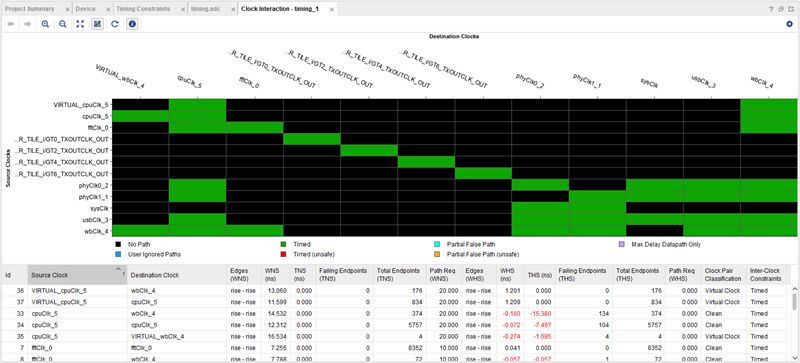
Revision History

Revision History
       The following table shows the revision history for this document.

                           Section                                           Revision Summary
                                             02/08/2021 Version 2020.2
        Release updates.                                  Validated for Xilinx release 2020.2.
                                             07/23/2020 Version 2020.1
        Release updates.                                  General 2020.1 release updates.

UG945 (v2020.2) February 8, 2021                                                                 www.xilinx.com
                                                                           Send Feedback
Using Constraints                                                                                             2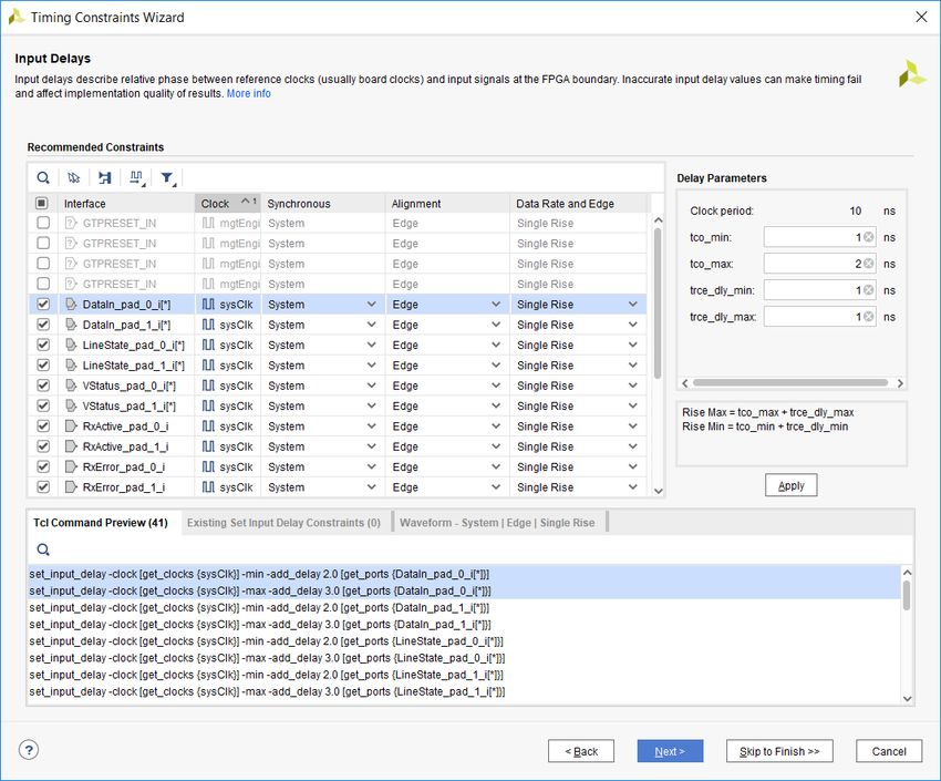
Table of Contents
       Revision History...............................................................................................................2

       Chapter 1: Using Constraints Tutorial................................................................ 4
           Tutorial Design Description....................................................................................................... 5
           Hardware and Software Requirements.................................................................................... 5
           Preparing the Tutorial Design Files...........................................................................................5

       Chapter 2: Lab 1: Defining Timing Constraints and Exceptions........... 6
           Step 1: Opening the Example Project....................................................................................... 6
           Step 2: Defining Constraint Sets and Files............................................................................. 11
           Step 3: Creating Timing Constraints....................................................................................... 13
           Step 4: Using the Constraints Editor....................................................................................... 21
           Step 5: Saving Constraints........................................................................................................27
           Step 6: Clock Interaction Report..............................................................................................29
           Step 7: Timing Summary Report............................................................................................. 30
           Conclusion..................................................................................................................................33

       Chapter 3: Lab 2: Setting Physical Constraints............................................ 34
           Step 1: Opening the Project..................................................................................................... 34
           Step 2: Adding Placement Constraints................................................................................... 35
           Step 3: Defining Additional Physical Constraints.................................................................. 37
           Step 4: Defining Constraints with Object Properties............................................................ 38
           Step 5: Saving Constraints........................................................................................................43
           Conclusion..................................................................................................................................43

       Appendix A: Additional Resources and Legal Notices............................. 44
           Xilinx Resources.........................................................................................................................44
           Documentation Navigator and Design Hubs.........................................................................44
           Please Read: Important Legal Notices................................................................................... 45

UG945 (v2020.2) February 8, 2021                                                                                                 www.xilinx.com
                                                                                                    Send Feedback
Using Constraints                                                                                                                             3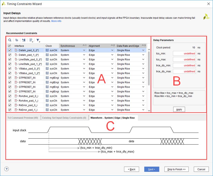
Chapter 1: Using Constraints Tutorial

                                                                                                    Chapter 1

Using Constraints Tutorial
            IMPORTANT! This tutorial requires the use of the Kintex®-7 family of devices. You will need to update
            your Vivado® tools installation if you do not have this device family installed. Refer to the Vivado Design
            Suite User Guide: Release Notes, Installation, and Licensing (UG973) for more information on Adding
            Design Tools or Devices.

       This tutorial is comprised of two labs that demonstrate aspects of constraining a design in the
       Vivado® Design Suite. The constraints format supported by the Vivado® Design Suite is called
       Xilinx® Design Constraints (XDC), which is a combination of the industry standard Synopsys®
       Design Constraints and proprietary Xilinx® constraints. For more information on Timing Closure,
       see the UltraFast Design Methodology Timing Closure Quick Reference Guide (UG1292).

            VIDEO: You can also learn more about defining constraints in the Vivado Design Suite by viewing the
            quick take video at Vivado Design Constraints Overview.

            TRAINING: Xilinx provides training courses that can help you learn more about the concepts presented in
            this document. Use these links to explore related courses:

            • Essentials of FPGA Design
            • Vivado Design Suite Static Timing Analysis and Xilinx Design Constraints

       XDCs are not just simple strings; they are Tcl commands that the Vivado Tcl interpreter
       sequentially reads and parses. You can enter design constraints in several ways at different points
       in the design flow. You can store XDCs in one or more files that can be added to a constraint set
       in Vivado Project Mode, or read the same files directly into memory using the read_xdc
       command in Non-Project mode. For more information on Project and Non-Project modes, refer
       to the Vivado Design Suite User Guide: Design Flows Overview (UG892). With a design open in
       Vivado tools, you can also type constraints as commands directly in the Tcl Console when
       working in the Vivado IDE or at the Tcl command prompt when working outside of the IDE. This
       is particularly powerful for defining, validating, and debugging new constraints interactively in
       the design.

       The Vivado Design Suite synthesis and implementation tools are timing driven. Having accurate
       and correct timing constraints is vital for meeting design goals and ensuring correct operation.
       Because the Vivado tools are timing driven, it is important to fully constrain a design, but not
       over-constrain, or under-constrain it. Over-constraining a design can lead to long compile times
       and sub-optimal results because the tool can struggle with unrealistic design objectives. Under-
       constraining a design can cause the Vivado tools to perform unnecessary optimizations, such as
       examining paths with multicycle delays or false paths, and prevent focus on the real critical paths.

UG945 (v2020.2) February 8, 2021                                                                       www.xilinx.com
                                                                                Send Feedback
Using Constraints                                                                                                   4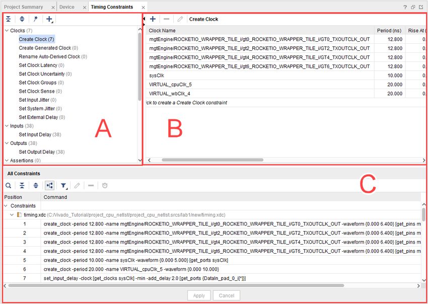
Chapter 1: Using Constraints Tutorial

       This tutorial discusses different methods for defining and applying design constraints.

Tutorial Design Description
       The sample design used throughout this tutorial consists of a small design called
       project_cpu_netlist. There is a top-level EDIF netlist source file, as well as an XDC
       constraints file.

       The design targets an XC7K70T device. A small design is used to allow the tutorial to be run with
       minimal hardware requirements and to enable timely completion of the tutorial, as well as to
       minimize the data size.

Hardware and Software Requirements
       This tutorial requires that the 2016.3 Vivado Design Suite software release or later is installed.

       See the Vivado Design Suite User Guide: Release Notes, Installation, and Licensing (UG973) for a
       complete list and description of the system and software requirements.

Preparing the Tutorial Design Files
       You can find a ZIP file containing the files for this tutorial in the examples directory of the Vivado
       Design Suite software installation, at the following location:

       /Vivado//examples/Vivado_Tutorial.zip

       Extract the ZIP file contents from the software installation into any write-accessible location.

       The location of the extracted Vivado_Tutorial directory is referred to as the
        in this Tutorial.

       You can also extract the provided ZIP file at any time to restore the files to their starting
       condition.

       Note: You will modify the tutorial design data while working through this tutorial. Use a new copy of the
       original Vivado_Tutorial directory each time you start this tutorial.

UG945 (v2020.2) February 8, 2021                                                                  www.xilinx.com
                                                                            Send Feedback
Using Constraints                                                                                              5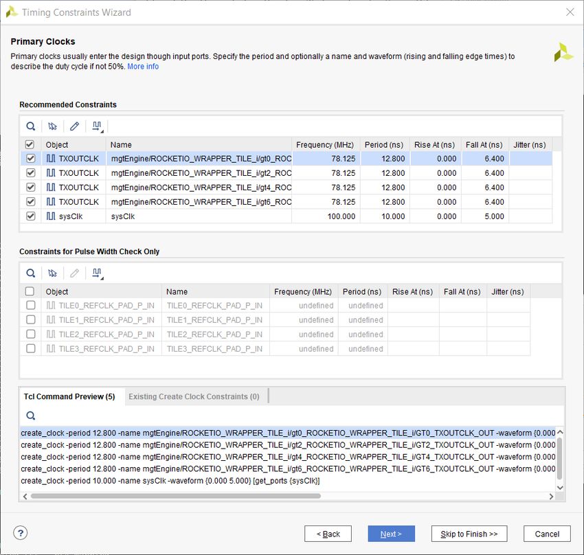
Chapter 2: Lab 1: Defining Timing Constraints and Exceptions

                                                                                             Chapter 2

Lab 1: Defining Timing Constraints
and Exceptions
       In this lab, you will learn two methods of creating constraints for a design. You will use the
       Kintex®-7 CPU Netlist example design that is included in the Vivado® IDE.

Step 1: Opening the Example Project
       1. Open Vivado IDE.
           • On Linux:
             1. Change the directory where the lab materials are stored.
                  cd /Vivado_Tutorial

             2. Launch the Vivado IDE: vivado
           • On Windows:
             1. Launch the Vivado Design Suite IDE:
                 Start → All Programs → Xilinx Design Tools → Vivado 2020.x → Vivado 2020.x
                 Note: Your Vivado Design Suite installation might be called something other than Xilinx Design
                 Tools on the Start menu.

             Note: As an alternative, click the Vivado 2020.x Desktop icon to start the Vivado IDE.

           The Vivado IDE Getting Started page contains links to open or create projects and to view
           documentation.
       2. From the Getting Started page, click Open Example Project, as shown in the following figure.

UG945 (v2020.2) February 8, 2021                                                                www.xilinx.com
                                                                          Send Feedback
Using Constraints                                                                                            6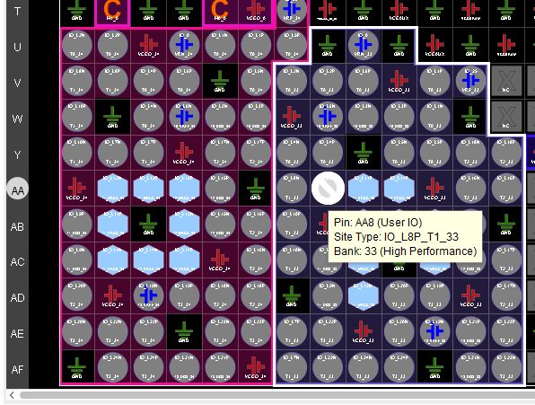
Chapter 2: Lab 1: Defining Timing Constraints and Exceptions

           The Open Example Project wizard opens to the Create an Example Project page, as shown in
           the following figure.

       3. Click Next.

UG945 (v2020.2) February 8, 2021                                                       www.xilinx.com
                                                                   Send Feedback
Using Constraints                                                                                   7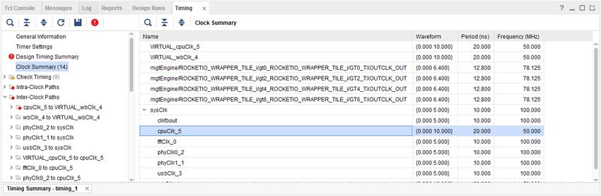
Chapter 2: Lab 1: Defining Timing Constraints and Exceptions

       4. In the Select Project Template page, select CPU (Synthesized), as shown in the following
          figure.

       5. Click Next.
       6. In the Project Name page, specify the project name and location, as shown in the following
          figure.

UG945 (v2020.2) February 8, 2021                                                        www.xilinx.com
                                                                     Send Feedback
Using Constraints                                                                                    8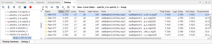
Chapter 2: Lab 1: Defining Timing Constraints and Exceptions

           • Project name: project_cpu_netlist
           • Project location:
       7. Click Next.
       8. In the Default Part page, select the default part as shown in the following figure.

           A New Project Summary appears, as shown in the following figure.

UG945 (v2020.2) February 8, 2021                                                           www.xilinx.com
                                                                       Send Feedback
Using Constraints                                                                                       9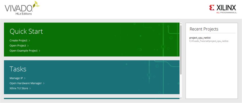
Chapter 2: Lab 1: Defining Timing Constraints and Exceptions
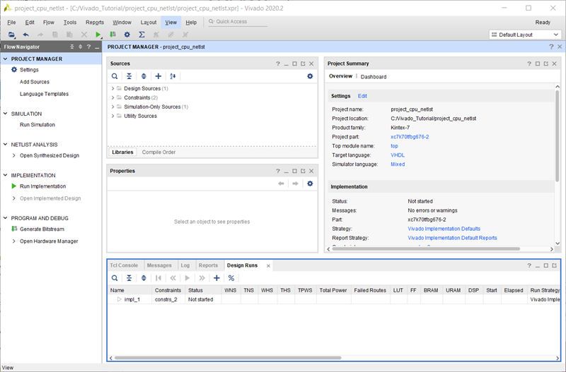
9. Click Finish to finish creating the project.
The Vivado IDE displays the default view of the opened project, as shown in the following
figure.
UG945 (v2020.2) February 8, 2021 www.xilinx.com
Send Feedback
Using Constraints 10Chapter 2: Lab 1: Defining Timing Constraints and Exceptions
Step 2: Defining Constraint Sets and Files
Start by creating a new constraint set and adding an empty XDC constraints file to it. The
example design already contains two constraint sets, but you do not use them for this lab.
1. From the Flow Navigator, click Add Sources in the Project Manager section.
2. From the Add Sources dialog box, select Add or create constraints.
3. Click Next.
4. From the Add or Create Constraints dialog box, use the Specify Constraint Set drop-down
menu to select Create Constraint Set as shown in the following figure.
5. In the Create Constraint Set dialog box, specify the constraint set name as lab1 and click
OK.
UG945 (v2020.2) February 8, 2021 www.xilinx.com
Send Feedback
Using Constraints 11Chapter 2: Lab 1: Defining Timing Constraints and Exceptions
6. Enable the Make active check box.
7. Click the Add button , and select Create File to add a new XDC file to the project.
The Create Constraints File dialog box appears.
8. Type timing as the file name, and leave the file location set to .
9. Click OK.
The timing.xdc file is added to the lab1 constraint set.
10. Click Finish to complete the creation of the new constraint set and XDC file.
You should see the new constraint set and XDC file in the Sources window, as shown in the
following figure. The constraint set is made active, as you directed when you created it.
11. In the Sources window (shown in the following figure), right-click timing.xdc and select
Set as Target Constraint File.
This sets the timing.xdc file as the target XDC file. All constraints added to the design are
saved in the target XDC file.
UG945 (v2020.2) February 8, 2021 www.xilinx.com
Send Feedback
Using Constraints 12Chapter 2: Lab 1: Defining Timing Constraints and Exceptions
Step 3: Creating Timing Constraints
In this step, you will open the synthesized design and use the Vivado® Timing Constraints wizard.
The Timing Constraints wizard analyzes the gate level netlist and finds missing constraints. Use
the Timing Constraints wizard to generate constraints for this design.
1. From the Flow Navigator, click Open Synthesized Design.
2. When the synthesized design opens, click Constraints Wizard under the Synthesized Design
section.
The introduction page of the Timing Constraints wizard appears. This page describes the
types of constraints that the wizard creates: Clocks, Input and Output Ports, and Clock
Domain Crossings.
3. After reading the page, click Next to continue.
The Primary Clocks page of the Timing Constraints wizard displays all the clock sources with
a missing clock definition. For this design, the wizard detected five missing clock constraints
that are needed to time logical paths, and four missing clock constraints that are only needed
to verify pulse width and minimum or maximum period requirements.
You will fill in the periods for the five missing primary clocks in the design. The second
category of clocks, shown in the Constraints for Pulse Width Check Only table, is optional.
For this example, do not add these last constraints.
4. In the Recommended Constraints table, each row of the wizard is a missing constraint. To
specify a constraint in the table, click the cell in the period column for the clock and type the
value from the following table to fill in the periods of the five missing primary clocks in the
design. When you set the period for a clock, the frequency is automatically populated.
UG945 (v2020.2) February 8, 2021 www.xilinx.com
Send Feedback
Using Constraints 13Chapter 2: Lab 1: Defining Timing Constraints and Exceptions
Table 1: Values to Use on the Primary Clock Page of the Wizard
Primary Clock Period (ns)
mgtEngine/ROCKETIO_WRAPPER_i/gt0_ROCKETIO_WRAPPER_TILE_i/GT0_TXOUTCLK_OUT 12.8
mgtEngine/ROCKETIO_WRAPPER_i/gt0_ROCKETIO_WRAPPER_TILE_i/GT2_TXOUTCLK_OUT 12.8
mgtEngine/ROCKETIO_WRAPPER_i/gt0_ROCKETIO_WRAPPER_TILE_i/GT4_TXOUTCLK_OUT 12.8
mgtEngine/ROCKETIO_WRAPPER_i/gt0_ROCKETIO_WRAPPER_TILE_i/GT6_TXOUTCLK_OUT 12.8
sysClk 10.0
If you do not want to enter a constraint for a specific clock, uncheck the box next to the
clock.
For more information about how the wizard finds these missing constraints, click the Quick
Help button (“?”) in the lower left-hand corner of the wizard. The quick help pages are
context specific and contain more information about the topologies the wizard is looking for
and an explanation as to why the constraint is being suggested.
The completed page looks like the following figure.
UG945 (v2020.2) February 8, 2021 www.xilinx.com
Send Feedback
Using Constraints 14Chapter 2: Lab 1: Defining Timing Constraints and Exceptions
5. Click Next to continue.
The primary clock constraints have been added to the design. Next, the wizard looks for
unconstrained generated clocks. Generated clocks are derived from primary clocks in the
FPGA fabric. A good example would be a binary counter used to create a divided clock.
In this design, the wizard determined that there are no unconstrained generated clocks.
6. Click Next to continue.
Next, the wizard looks for forwarded clocks. A forwarded clock is a generated clock on a
primary output port of the FPGA. These are commonly used for source synchronous buses
when the capture clock travels with the data.
The wizard has determined that there are no unconstrained forwarded clocks in the design.
7. Click Next to continue.
UG945 (v2020.2) February 8, 2021 www.xilinx.com
Send Feedback
Using Constraints 15Chapter 2: Lab 1: Defining Timing Constraints and Exceptions
Next, the wizard looks for external feedback delays. MMCM or PLL feedback delay outside
the FPGA is used to compute the clock delay compensation in the timing reports.
The wizard did not find any unconstrained MMCM external feedback delays in the design.
8. Click Next to continue.
Next, the wizard looks at the input delays. The following figure shows the Input Delay page
of the Timing Constraints wizard. There are three sections to the page.
In section A, you can see all the input ports that are missing input delay constraints in the
design. In this table, you select the timing template you would like to use to constrain the
input.
In section B, you provide the delay values for the template. This section will change
depending on the template chosen in section A.
In section C, there are three tabs:
• Tcl Command Preview: Previews the Tcl commands that will be used to constrain the
design.
UG945 (v2020.2) February 8, 2021 www.xilinx.com
Send Feedback
Using Constraints 16Chapter 2: Lab 1: Defining Timing Constraints and Exceptions
• Existing Set Input Delay Constraints: Shows input delay constraints that exist in the
design.
• Waveform: Displays the waveform associated with the template.
Next, you will fill out the form based on the following table.
9. Click the Clock column header to sort the table alphabetically by clock name.
10. Select the template in section A, enter the values in section B, and observe the Tcl
commands, existing input delays, and the template specific waveform in section C.
11. Skip entering the first four constraints shown in following table by unchecking the box to the
left of the constraint. In this particular case, you false path these paths from the
GTPRESET_IN port later, as it is an asynchronous reset signal synchronized inside the design.
The blocks of colored rows in the following table can all be entered at the same time in the
Input Delays page of the Timing Constraints wizard, shown in the following figure, by
selecting multiple rows in the wizard (use the Shift or Ctrl buttons and click to select multiple
rows) and then entering the values once. Some inputs are constrained relative to virtual
clocks, because they are captured by an internal generated clock with a waveform different
than the board clock. In this case, the wizard creates a virtual clock with the same frequency
and waveform as the internal clock, and recommends a constraint relative to the virtual clock.
The following table is shaded to indicate which groups of signals can be entered in this
manner.
Table 2: Input Constrain Values
Data Rate and tco_min tco_max
Interface Clock Synchronous Alignment trce_dly_min (ns) trce_dly_max (ns)
Edge (ns) (ns)
GTPRESET_IN mgtEngine/... System Edge Single Rise Uncheck constraint – will false path later
GTPRESET_IN mgtEngine/... System Edge Single Rise Uncheck constraint – will false path later
GTPRESET_IN mgtEngine/... System Edge Single Rise Uncheck constraint – will false path later
GTPRESET_IN mgtEngine/... System Edge Single Rise Uncheck constraint – will false path later
DataIn_pad_0_i[ sysClk System Edge Single Rise 1 2 1 1
*]
DataIn_pad_1_i[ sysClk System Edge Single Rise 1 2 1 1
*]
LineState_pad_ sysClk System Edge Single Rise 1 2 1 1
0_i[*]
LineState_pad_ sysClk System Edge Single Rise 1 2 1 1
1_i[*]
VStatus_pad_0_ sysClk System Edge Single Rise 1 2 1 1
i[*]
VStatus_pad_1_ sysClk System Edge Single Rise 1 2 1 1
i[*]
RxActive_pad_0 sysClk System Edge Single Rise 1 2 1 1
_i
RxActive_pad_1 sysClk System Edge Single Rise 1 2 1 1
_i
Rx_Error_pad_0 sysClk System Edge Single Rise 1 2 1 1
_i
Rx_Error_pad_1 sysClk System Edge Single Rise 1 2 1 1
_i
UG945 (v2020.2) February 8, 2021 www.xilinx.com
Send Feedback
Using Constraints 17Chapter 2: Lab 1: Defining Timing Constraints and Exceptions
Table 2: Input Constrain Values (cont'd)
Data Rate and tco_min tco_max
Interface Clock Synchronous Alignment trce_dly_min (ns) trce_dly_max (ns)
Edge (ns) (ns)
Rx_Valid_pad_0_ sysClk System Edge Single Rise 1 2 1 1
i
Rx_Valid_pad_1_ sysClk System Edge Single Rise 1 2 1 1
i
TxReady_pad_0 sysClk System Edge Single Rise 1 2 1 1
_i
TxReady_pad_1 sysClk System Edge Single Rise 1 2 1 1
_i
usb_vbus_paf_0 sysClk System Edge Single Rise 1 2 1 1
_i
usb_vbus_paf_1 sysClk System Edge Single Rise 1 2 1 1
_i
or1200_clmode VIRTUAL_cpuCl System Edge Single Rise 0.1 2.5 0.1 0.2
k_5
or1200_pic_ints VIRTUAL_cpuCl System Edge Single Rise 0.1 2.5 0.1 0.2
k_5
reset VIRTUAL_cpuCL System Edge Single Rise 0.1 2.5 0.1 0.2
K_5
The following figure shows the completed input delay page. Note the four constraints being
skipped.
UG945 (v2020.2) February 8, 2021 www.xilinx.com
Send Feedback
Using Constraints 18Chapter 2: Lab 1: Defining Timing Constraints and Exceptions
12. When you have successfully entered all the input constraint values, click Next.
The Output Delays page of the wizard displays all the outputs that are unconstrained in the
design. The page layout is very similar to the inputs page.
13. In the Output Delays page, click the Clock header to sort the table alphabetically by clock
name.
14. Use the following table to constrain all the outputs as you did for the input constraint values.
You can select multiple lines in the wizard at once and edit several entries as the same time.
Table 3: Output Constraint Values
Data Rate and thd trce_dly_max
Interface Clock Synchronous Alignment tsu (ns) trce_dly_min (ns)
Edge (ns) (ns)
OpMode_pad_0_ sysClk System Setup/Hold Single Rise 1.0 0.1 0.1 0.1
o[*]
OpMode_pad_1_ sysClk System Setup/Hold Single Rise 1.0 0.1 0.1 0.1
o[*]
VControl_pad_0_ sysClk System Setup/Hold Single Rise 1.0 0.1 0.1 0.1
o[*]
VControl_pad_0_ sysClk System Setup/Hold Single Rise 1.0 0.1 0.1 0.1
o[*]
UG945 (v2020.2) February 8, 2021 www.xilinx.com
Send Feedback
Using Constraints 19Chapter 2: Lab 1: Defining Timing Constraints and Exceptions
Table 3: Output Constraint Values (cont'd)
Data Rate and thd trce_dly_max
Interface Clock Synchronous Alignment tsu (ns) trce_dly_min (ns)
Edge (ns) (ns)
SuspendM_pad_0 sysClk System Setup/Hold Single Rise 1.0 0.1 0.1 0.1
_o
SuspendM_pad_1 sysClk System Setup/Hold Single Rise 1.0 0.1 0.1 0.1
_o
TermSel_pad_0_o sysClk System Setup/Hold Single Rise 1.0 0.1 0.1 0.1
TermSel_pad_1_o sysClk System Setup/Hold Single Rise 1.0 0.1 0.1 0.1
TxValid_pad_0_o sysClk System Setup/Hold Single Rise 1.0 0.1 0.1 0.1
TxValid_pad_1_o sysClk System Setup/Hold Single Rise 1.0 0.1 0.1 0.1
VControl_Load_p sysClk System Setup/Hold Single Rise 1.0 0.1 0.1 0.1
ad_0_o
VControl_Load_p sysClk System Setup/Hold Single Rise 1.0 0.1 0.1 0.1
ad_1_o
XcvSelect_pad_0_ sysClk System Setup/Hold Single Rise 1.0 0.1 0.1 0.1
o
XcvSelect_pad_1_ sysClk System Setup/Hold Single Rise 1.0 0.1 0.1 0.1
o
phy_rst_pad_0_o sysClk System Setup/Hold Single Rise 1.0 0.1 0.1 0.1
phy_rst_pad_1_o sysClk System Setup/Hold Single Rise 1.0 0.1 0.1 0.1
DataOut_pad_0_ VIRTUAL_wbClk_4 System Setup/Hold Single Rise 2.1 0.6 0.1 0.0
o[*]
DataOut_pad_1_ VIRTUAL_wbClk_4 System Setup/Hold Single Rise 2.1 0.6 0.1 0.0
o[*]
Or1200_pm_out[ VIRTUAL_wbClk_4 System Setup/Hold Single Rise 2.1 0.6 0.1 0.0
*]
15. Click Next to continue.
The wizard looks for any unconstrained combinational paths through the design. A
combinational path is a path that traverses the FPGA without being captured by any
sequential elements. This design does not contain any combinational paths.
16. Click Next to continue.
Physically exclusive clock groups are clocks that do not exist in the design at the same time.
There are no unconstrained physically exclusive clock groups in this design.
17. Click Next to continue.
Logically exclusive clocks with no interaction are clocks that are active at the same time
except on shared clock tree sections. Then these clocks do not have logical paths between
each other and outside the shared sections, they are logically exclusive. There are no
unconstrained logically exclusive clock groups with no interaction in the design.
18. Click Next to continue.
Logically exclusive clocks with interaction are clocks that are active at the same time except
on shared clock tree sections. When these clocks have logical paths between each other, only
the clocks limited to the shared clock tree sections are logically exclusive and are therefore
constrained differently than the logically exclusive clock with no interaction. There are no
unconstrained logically exclusive clock groups with interaction in the design.
UG945 (v2020.2) February 8, 2021 www.xilinx.com
Send Feedback
Using Constraints 20Chapter 2: Lab 1: Defining Timing Constraints and Exceptions
19. Click Next to continue.
The Asynchronous Clock Domain Crossings page recommends constraints for safe clock
domain crossings. This design does not contain any unconstrained clock domain crossings.
20. Click Next to continue.
The following figure shows the final page of the Timing Constraints wizard. All the constraints
that were generated by the wizard can be viewed by clicking the links. If you would like to
run any reports once the wizard is finished, you can select them using the check boxes in the
wizard.
21. Click Finish to complete the Timing Constraints wizard.
Step 4: Using the Constraints Editor
1. Click Edit Timing Constraints from the Flow Navigator under the Synthesized Design section.
The Vivado IDE displays the Timing Constraints window.
UG945 (v2020.2) February 8, 2021 www.xilinx.com
Send Feedback
Using Constraints 21Chapter 2: Lab 1: Defining Timing Constraints and Exceptions
There are three sections to the Timing Constraints window, as shown in the above figure:
• Constraints tree view: Labeled as section A. This section displays standard timing
constraints, grouped by category. Double-clicking a constraint in this section opens a form
to help you define the selected constraint.
• Constraints Spreadsheet: Labeled as section B. This section displays timing constraints of
the type currently selected in the Constraints tree view. If you prefer, you can use this to
directly define or edit constraints instead of using the Constraints wizard.
• All Constraints: Labeled as section C. This section displays all the timing constraints that
currently exist in the design.
The Timing Constraints wizard identifies missing clocks, I/O delays, and clock domain
crossings exceptions, but it does not handle general timing exceptions. You are going to use
the timing constraints editor to create the exceptions that exist in this design.
First, you are going to set a false path on the GTPRESET_IN input. This is the input
constraint that you skipped by unchecking it on the input delay page of the Timing
Constraints wizard. The GTPRESET_IN signal is an asynchronous reset that is properly
synchronized inside the design. For more information about false paths, see this link in the
Vivado Design Suite User Guide: Using Constraints (UG903).
2. In the Constraints tree view, scroll down to the Exceptions category, shown in the following
figure.
UG945 (v2020.2) February 8, 2021 www.xilinx.com
Send Feedback
Using Constraints 22Chapter 2: Lab 1: Defining Timing Constraints and Exceptions
3. Double-click Set False Path.
4. To the right of the From text box, click the Choose Start Points button .
The Specify Start Points dialog box appears.
5. From the Find names of type drop-down list, select I/O Port as shown in the following figure.
6. Under Options, select "Name", "contains" and in the search pattern text box, enter
GTPRESET_IN.
7. Click the Find button.
8. Select GTPRESET_IN in the found results text box and press the right arrow to move it to the
selected names text box.
TIP: You can also double-click GTPRESET_IN to move it from the Find results list to the Selected
names list.
Notice that the Command field displayed at the bottom of the dialog box changes as you
perform these different actions. The get_ports command changes to:
get_ports "*GTPRESET_IN*"
UG945 (v2020.2) February 8, 2021 www.xilinx.com
Send Feedback
Using Constraints 23Chapter 2: Lab 1: Defining Timing Constraints and Exceptions
9. Click Set in the Specify Start Points dialog box.
The completed Set False Path dialog box is shown in the following figure. Notice the
following command text in the Command field at the bottom of the dialog box:
set_false_path -from [get_ports "*GTPRESET_IN*"]
The Vivado IDE displays the Tcl command form of all constraints created via the dialogs for
your review. This is useful for learning the Tcl command syntax, and for verifying the final
constraint before adding it.
UG945 (v2020.2) February 8, 2021 www.xilinx.com
Send Feedback
Using Constraints 24Chapter 2: Lab 1: Defining Timing Constraints and Exceptions
10. Click OK to close the Timing Constraint Editor.
Vivado creates the false path exception.
Add a MultiCycle Path
Next, you will add a multicycle path using the constraints editor.
1. Double-click Set Multicycle Path under the Exceptions category of the tree.
2. In the Set Multicycle Path dialog box, set the path multiplier to 2.
3. In the Through entry box, type the following string (alternately, you can copy and paste it
from here):
[get_pins cpuEngine/or1200_cpu/or1200_alu/*]
UG945 (v2020.2) February 8, 2021 www.xilinx.com
Send Feedback
Using Constraints 25Chapter 2: Lab 1: Defining Timing Constraints and Exceptions
Notice that the Tcl command displays in the Command field.
4. Click OK.
A new multicycle path is added to the constraints editor in the
section, as shown in the following figure.
Adding a multicycle path by default pushes the setup timing to the specified number of
cycles (N), but it also pushes the hold timing to N – 1 cycles. This is usually not what is intended
and could cause Vivado tools to spend a lot of time fixing large hold violations. In this case
you want the setup path clock. To achieve this, you need to define another multicycle path on
the hold edge to 1, such that N – 1 is zero. For more information about this situation, see this
link in the Vivado Design Suite User Guide: Using Constraints (UG903).
5. Double-click Set Multicycle Path under the Exceptions category of the tree for a second
time.
Note that all the fields you entered previously are still filled in.
6. In the Set Multicycle Path dialog box, change the Path Multiplier to 1.
7. Select the Options tab.
8. Under Setup/Hold, select the check box that says Use path multiplier.
9. Use the pull-down to select hold (minimum delay).
UG945 (v2020.2) February 8, 2021 www.xilinx.com
Send Feedback
Using Constraints 26Chapter 2: Lab 1: Defining Timing Constraints and Exceptions
10. Click OK.
Now you have a fully constrained design in memory. To save the constraints to disk, proceed
to Step 5: Saving Constraints.
Step 5: Saving Constraints
Constraint management is an important step of the design flow, and the Vivado Design Suite
provides you the flexibility of adding new constraints into an existing constraint file, overwriting
existing constraints, or creating a new constraints file to track design changes or complete
missing constraints.
You have created a few timing exceptions for the design, but the exceptions exist only in memory
and not on disk yet. You need to save the exceptions to the timing.xdc file.
1. From the Sources window in Vivado, double-click timing.xdc under Constraints → lab1.
UG945 (v2020.2) February 8, 2021 www.xilinx.com
Send Feedback
Using Constraints 27Chapter 2: Lab 1: Defining Timing Constraints and Exceptions
2. Scroll to the bottom of the file and notice that the set_false_path and set_multicycle_path
constraints do not exist in the file. This is also reflected in the Timing Constraints Editor as
, as shown in the following figure.
3. Click the Save Constraints button or use the File → Constraints → Save As command from
the main menu.
4. Click the Reload link in the banner of the timing.xdc tab to reload the constraints file from
disk. Notice that the false path and multi-cycle paths are now visible in the timing.xdc text
file, as shown in the following figure.
Note: The Tcl variable _xlnx_shared_i0 is automatically introduced by Vivado to share the same collection
of objects between multiple timing constraints.
UG945 (v2020.2) February 8, 2021 www.xilinx.com
Send Feedback
Using Constraints 28Chapter 2: Lab 1: Defining Timing Constraints and Exceptions
Step 6: Clock Interaction Report
After or during constraints creation, you must verify that the constraints are complete and safe.
Vivado Design Suite times all clocks together by default unless you specify otherwise by defining
clock groups or other timing exceptions. The set_clock_groups command specifies
asynchronous or exclusive clock domains and disables timing analysis between them. You can
also use the set_false_path exception between two clocks to disable timing on all paths between
them, or use it on specific netlist objects to only disable some paths. The set_multicycle_path
exception modifies the clock edges used during timing analysis instead of the default single cycle
assumption. For more information on using these constraints, see the Vivado Design Suite User
Guide: Using Constraints (UG903).
Vivado automatically infers timing path requirements for paths that cross between two different
clock domains, called inter-clock paths, making assumptions regarding phase and offset. The
Report Clock Interaction command reports inter-clock paths, to help identify potential problems
such as unrealistic setup or hold requirements between two clocks, or unsafe timing between
asynchronous clocks (no known phase relationship) which can lead to unstable hardware
behavior. For more information on the Clock Interaction Report, see the "Details of the Clock
Interaction Report" in Vivado Design Suite User Guide: Design Analysis and Closure Techniques
(UG906).
1. From the Flow Navigator, select Synthesized Design → Report Clock Interaction and click OK
in the Report Clock Interaction dialog box to accept the default settings.
UG945 (v2020.2) February 8, 2021 www.xilinx.com
Send Feedback
Using Constraints 29Chapter 2: Lab 1: Defining Timing Constraints and Exceptions
The Vivado IDE generates a graphical matrix illustrating the relationship of the various clocks
in the design, as shown in the previous figure. For this design, the primary clock (sysClk)
connects to an MMCM, which generates six additional clocks. The clock interactions shown
are between these generated clocks. In addition, the Timing Constraints wizard created
additional generated clocks and virtual clocks to fully constrain the design.
In general, the Clock Interaction report shows clock pairs with no path between them (black),
with paths safely timed (green and light blue), with paths not safely timed (red and orange)
and with paths covered by Max Delay Datapath Only constraints. In this design, only black
cells and green cells are displayed in the matrix.
IMPORTANT! Green in the matrix does not mean that timing is met, it simply means that the timing
constraints and the clock tree topologies allows safe timing analysis and accurate slack computation.
In the Clock Interaction report, unsafe means there is no common primary clock (no known
phase relationship), or no common node (uncommon scenario that results in unknown phase
relationship), or no common clock period within the first 1000 clock cycles of the source and
destination clocks. The Vivado timing engine selects edges on the launch and capture clocks
based on the first 1000 cycles, but these edges might not reflect the most pessimistic
analysis between the clocks.
TIP: The colors described here are the default colors. Your colors might be configured differently from
those shown in the previous figure.
2. Close the Clock Interaction window by clicking the Close button in the window tab.
Step 7: Timing Summary Report
Timing paths start and end at clocked elements. Input and Output ports are not sequential
elements, and by default Vivado timing analysis does not time paths to or from I/O ports in the
design, unless input/output delay constraints are specified.
In this step you will generate and interpret timing reports in Vivado.
1. Select Reports → Timing → Report Timing Summary.
2. Click OK to generate the report, using the default options.
The Timing Summary tab opens, as shown in the following figure.
UG945 (v2020.2) February 8, 2021 www.xilinx.com
Send Feedback
Using Constraints 30Chapter 2: Lab 1: Defining Timing Constraints and Exceptions
The design passes setup timing but fails hold analysis. Before implementing the design, timing
analysis uses estimated net delays that represent ideal placement. Small hold violations are
common at this point of the flow and will be fixed during the routing step. For now, review
the content of the report.
3. Click the Worst Negative Slack link in the design timing summary section to see the worst
timing path in the design, as shown in the following figure.
4. When the worst path is selected, press the F4 key to bring up its schematic. The following
figure shows the worst setup path in the design.
5. In the timing summary tree, select Check Timing.
• There are nine issues flagged by Check Timing shown in the following figure.
• Eight of these are pulse_width_clock checks, which were also flagged by the Timing
Constraints wizard, but were not constrained. These violations have low severity because
the corresponding missing clocks are not needed for timing logic paths.
• The remaining issue flagged by Check Timing is a no_input_delay check, which is due to a
missing input constraint on the reset signal that was set to false_path. This can also be
ignored in this example.
UG945 (v2020.2) February 8, 2021 www.xilinx.com
Send Feedback
Using Constraints 31Chapter 2: Lab 1: Defining Timing Constraints and Exceptions
6. In the timing summary tree, select the Clock Summary, as shown in the following figure.
The clock summary section of the timing summary report lists all the clocks in the design and
shows the resulting frequencies and waveforms of each clock. The hierarchy shows the
relationship between the generated clocks and the primary clock (for example, cpuClk_5 vs.
sysClk). For example, it shows that cpuClk_5 is generated from primary clock SysClk,
and its period is twice that of sysClk.
The remaining sections of the timing summary report group paths by their type. Each section
lists the top ten paths (specified when the report was generated) in that group. These include
inter-clock paths, intra-clock paths, other path groups, user ignored paths, and unconstrained
paths. Clicking the roots will show a summary of the paths beneath. Expanding the tree
further will ultimately display the top timing paths for each group.
UG945 (v2020.2) February 8, 2021 www.xilinx.com
Send Feedback
Using Constraints 32Chapter 2: Lab 1: Defining Timing Constraints and Exceptions
Conclusion
At this point you can either continue to Lab #2: Setting Physical Constraints, or exit the Vivado
Design Suite and continue later. Lab #2 uses the project created during this lab, so be sure not to
delete your work.
In this lab, you learned:
• How to Create a constraint set and set a target constraint file
• How to add timing constraints to a design using the Timing Constraints Wizard
• How to add timing exceptions using the Timing Constraints Editor
• The importance of saving constraints to disk versus in-memory constraints
• How to generate the clock interaction report and properly interpret the resulting matrix
• How to generate the timing summary report and properly interpret the results
UG945 (v2020.2) February 8, 2021 www.xilinx.com
Send Feedback
Using Constraints 33Chapter 3: Lab 2: Setting Physical Constraints
Chapter 3
Lab 2: Setting Physical Constraints
In this lab, you will create physical constraints for the CPU Netlist design, observing how actions
in the GUI translate into Tcl commands. Using Tcl commands, complex operations are easily
scripted for repeated use, at various stages of the flow.
Note: If you are continuing from Lab 1, and your design is open, skip ahead to Step 2: Adding Placement
Constraints.
Step 1: Opening the Project
This lab continues from the end of Lab #1 in this tutorial. You must complete Lab #1 prior to
beginning Lab #2. If you closed the tool, or closed the tutorial project at the end of Lab #1, you
will need to open them again.
1. Start by loading the Vivado® Integrated Design Environment (IDE) by doing one of the
following
• Launch Vivado IDE from the icon on the Windows desktop.
• Select Windows → Programs → Xilinx Design Tools → Vivado 2020.x → Vivado 2020.x.
• Type vivado from a command terminal.
From the Getting Started screen you can open recent projects.
2. Under Recent Projects, click project_cpu_netlist as shown in the following figure.
UG945 (v2020.2) February 8, 2021 www.xilinx.com
Send Feedback
Using Constraints 34Chapter 3: Lab 2: Setting Physical Constraints
Step 2: Adding Placement Constraints
Explore some of the design hierarchy, and begin placing logic elements to create physical
constraints.
1. From the Flow Navigator, select Open Synthesized Design. The synthesized design might
already be open if you came directly to this step.
The synthesized netlist opens with the Device window displayed.
2. Select the Netlist window and expand the clkgen hierarchy.
3. Expand the Leaf Cells folder and select the instance mmcm_adv_inst (MMCME2_ADV).
4. Look in the Cell Properties view, under the Properties tab, and notice that the STATUS is
UNPLACED, and there are no IS_LOC_FIXED or IS_BEL_FIXED properties shown.
5. Check this in the Tcl Console by typing:
get_property IS_LOC_FIXED [get_cells clkgen/mmcm_adv_inst]
This returns a zero, indicating the object is not fixed to a location.
6. Zoom into the bottom right of the Device view, to display the lower half of Clock Region
X1Y0, to prepare for placing the selected object. See the following figure.
UG945 (v2020.2) February 8, 2021 www.xilinx.com
Send Feedback
Using Constraints 35Chapter 3: Lab 2: Setting Physical Constraints
TIP: It is easier to place logic in the Device window if Routing Resources are not displayed. If they are
displayed, select the Routing Resources toolbar button to disable.
7. In the Netlist window, click on the mmcm_adv_inst and drag it into the Device window to
place it into the bottom right MMCME2_ADV.
8. Look in the Tcl Console. You should see something like these three commands:
startgroup
place_cell clkgen/mmcm_adv_inst MMCME2_ADV_X1Y0/MMCME2_ADV
endgroup
The startgroup and endgroup Tcl commands bracket sequences of commands to support
the undo function in the Vivado tools. If you make a mistake, you can use the undo command
in the Tcl Console, or the Edit → Undo command. This will undo the placement and allow you
to redo it. For more information on startgroup, endgroup, and undo, refer to the Vivado
Design Suite Tcl Command Reference Guide (UG835).
9. Look at the Properties tab of the Cell Properties window for the MMCM cell you placed.
Notice that the IS_BEL_FIXED and IS_LOC_FIXED properties are now checked, reflecting
that the object has been placed, as shown in the following figure. The STATUS property is set
to FIXED as well.
Note: The Cell Drag and Drop mode in the Device window determines whether only IS LOC FIXED is
set, or IS BEL FIXED is also set, when placing objects. Refer to this link in the Vivado Design Suite User
Guide: Using the Vivado IDE (UG893) for more information on the Device window.
UG945 (v2020.2) February 8, 2021 www.xilinx.com
Send Feedback
Using Constraints 36Chapter 3: Lab 2: Setting Physical Constraints
The IS_BEL_FIXED and IS_LOC_FIXED properties on the object are physical constraints
reflecting the placement of the object. These constraint are used by Vivado implementation,
and will not be changed by the tool. However, if the properties are invalid, they will cause
errors downstream in the design flow.
Notice that when you place mmcm_adv_inst in the Device window, the Save Constraints
button is enabled. The physical constraints are added to the Vivado tool in-memory
design, but are not yet saved to the target constraint file.
Step 3: Defining Additional Physical
Constraints
In this step, you will define additional physical constraints to the design, such as the
PACKAGE_PIN, and PROHIBIT constraints.
1. Select Layout → I/O Planning to open the I/O Planning view layout from the Layout Selector
in the tool bar menu.
The I/O Planning view layout displays the Package window, as well as the I/O Ports and
Package Pins windows, to facilitate planning the I/O port assignment for the design.
For the purposes of this tutorial, assume the PCB layout has been completed, and therefore
certain pins are not accessible on the FPGA package. You can prohibit the Vivado tool from
using these pins during placement and routing (assuming you have not already specified all of
your I/O assignments).
2. Select the AA8 pin in the Package window.
UG945 (v2020.2) February 8, 2021 www.xilinx.com
Send Feedback
Using Constraints 37Chapter 3: Lab 2: Setting Physical Constraints
TIP: Use the X and Y-axis values on the edge of the Package window to help you locate this pin on the
package. You may need to zoom in or enlarge the Package window to make the values visible.
3. With the pin selected, right-click and select Set Prohibit.
When you unselect the pin, you will notice the site now has a red circle with a diagonal line
through it, indicating that it is unusable.
4. Look at the Tcl Console and review the Tcl command produced by the Vivado IDE.
startgroup
set_property prohibit 1 [get_bels IOB_X1Y34/PAD]
set_property prohibit 1 [get_sites AA8]
endgroup
Step 4: Defining Constraints with Object
Properties
You can create timing and placement constraints as you have seen in this tutorial. You can also
change the properties of cells to control how they are handled by Vivado implementation. Many
physical constraints are defined as properties on a cell object.
For example, if you discover a timing issue with a RAM in the design, to avoid resynthesis, you
can change a property of the RAM cell to add in pipeline registers. After confirming with the
designer and validation teams that this is an acceptable approach, you can change the design.
UG945 (v2020.2) February 8, 2021 www.xilinx.com
Send Feedback
Using Constraints 38Chapter 3: Lab 2: Setting Physical Constraints
Setting Cell Properties
Because it can be too time consuming and costly to go back to the RTL after synthesis, you can
make changes in the netlist as follows.
1. Select Edit → Find to open the Find dialog box, as shown in the following figure.
a. Select Cells from the Find drop-down list.
b. Under Properties, set PRIMITIVE_TYPE to BMEM.BRAM.
c. Make sure that Search Hierarchy is selected, as shown in the following figure.
d. Click OK.
The Find Results window opens.
2. Select the Show Search button on the toolbar menu of the Find Results window.
3. Search for ingressLoop, and select the following cell: fftEngine/fftInst/
ingressLoop[7].ingressFifo/
In the Properties tab of the Cell Properties window, you can see the DOA_REG and
DOB_REG are set to zero, indicating that the output registers are disabled.
UG945 (v2020.2) February 8, 2021 www.xilinx.com
Send Feedback
Using Constraints 39Chapter 3: Lab 2: Setting Physical Constraints
4. Generate a custom timing report from this cell directly from the Tcl Console. The Tcl
command to enter is:
report_timing -from [get_cells fftEngine/fftInst/
ingressLoop[7].ingressFifo/
buffer_fifo/infer_fifo.block_ram_performance.fifo_ram_reg]
TIP: You can copy and paste the cell name from the General tab of the Cell Properties window into the
Tcl Console.
5. In the upper-right corner of the Tcl Console, click the Maximize button to maximize the
window and better view the timing report.
6. In the data path section of the report, 1.800 ns is added by this RAMB.
7. Restore the Tcl Console to its normal size.
8. In the Properties tab of the Cell Properties window, select the DOA_REG and DOB_REG
properties for this cell and change their values for "0" to "1."
You can see two set_property commands run in the Tcl Console.
set_property DOA_REG {1} [get_cells {fftEngine/fftInst/
ingressLoop[7].ingressFifo/
buffer_fifo/infer_fifo.block_ram_performance.fifo_ram_reg}]
set_property DOB_REG {1} [get_cells {fftEngine/fftInst/
ingressLoop[7].ingressFifo
/buffer_fifo/infer_fifo.block_ram_performance.fifo_ram_reg}]
9. Run the timing report from the selected cell. The Tcl command to enter is:
report_timing -from [get_cells fftEngine/fftInst/
ingressLoop[7].ingressFifo
/buffer_fifo/infer_fifo.block_ram_performance.fifo_ram_reg]
10. Notice that the data path delay for the RAM is now 0.622 ns.
Setting Design Properties
Next, set the configuration mode on the design. This is another property that results in a physical
constraint, in this case a property of the design rather than of a cell. To begin, list all of the
properties of the current design.
1. List the properties of the design in the Tcl Console:
list_property [current_design]
UG945 (v2020.2) February 8, 2021 www.xilinx.com
Send Feedback
Using Constraints 40Chapter 3: Lab 2: Setting Physical Constraints
This command returns the list of all defined properties on the current design. To make the list
more readable, you can use the standard Tcl join command to combine the properties
output with “\n” newline character, resulting in each property displaying on a separate line.
join [list_property [current_design]] \n
2. The specific property of interest is CONFIG_MODE. To see what values this particular
property can accept, use the list_property_value Tcl command:
join [list_property_value CONFIG_MODE [current_design]] \n
3. Use the Tools → Edit Device Properties command to set the CONFIG_MODE property for
the current design.
The Edit Device Properties dialog box opens.
4. Click Configuration Modes to open the Configuration Modes panel.
5. Scroll down on the page to find the Master Serial configuration mode option, as shown in the
following figure.
UG945 (v2020.2) February 8, 2021 www.xilinx.com
Send Feedback
Using Constraints 41Chapter 3: Lab 2: Setting Physical Constraints
6. Select the Master Serial configuration mode as shown, and click OK to close the dialog box.
The Tcl Console shows the set_property command that sets the CONFIG_MODE:
set_property CONFIG_MODE M_SERIAL [current_design]
The configuration mode has now been set.
7. Use the get_property command to confirm that the CONFIG_MODE property was
correctly set:
get_property CONFIG_MODE [current_design]
The property value M_SERIAL is returned by the Vivado tool.
UG945 (v2020.2) February 8, 2021 www.xilinx.com
Send Feedback
Using Constraints 42Chapter 3: Lab 2: Setting Physical Constraints
Step 5: Saving Constraints
Notice that the Save Constraints icon is enabled because there are new design constraints. The
cell and design properties you modified in Lab #2 have been added to the Vivado tool in-memory
design, but are not yet saved to the target constraint file.
1. Click the Save Constraints button .
The physical constraints you defined in Lab #2 are saved to the target constraint file.
2. Select the target XDC (in this case, timing.xdc) from the active constraint set in the
Sources window to open the file in the Vivado IDE text editor.
Note: You might need to click the Reload link to update the file if it is already opened in the GUI.
Notice that the seven set_property commands you used in Lab #2 are saved to the
constraint file. Only design constraints are written to the XDC file, not the object queries or
reporting commands that you also used in this lab.
3. Look for the following constraints in the open constraint file:
set_property BEL MMCME2_ADV [get_cells clkgen/mmcm_adv_inst]
set_property LOC MMCME2_ADV_X1Y0 [get_cells clkgen/mmcm_adv_inst]
set_property PROHIBIT true [get_bels IOB_X1Y34/PAD]
set_property PROHIBIT true [get_sites AA8]
set_property DOA_REG 1 [get_cells \
{fftEngine/fftInst/ingressLoop[7].ingressFifo/buffer_fifo/
infer_fifo.block_ram_\
performance.fifo_ram_reg}]
set_property DOB_REG 1 [get_cells \
{fftEngine/fftInst/ingressLoop[7].ingressFifo/buffer_fifo/
infer_fifo.block_ram_\
performance.fifo_ram_reg}]
set_property CONFIG_MODE M_SERIAL [current_design]
4. Exit the Vivado IDE.
Conclusion
In this lab, you learned how to use both the Vivado IDE and the Tcl Console to create and verify
physical constraints. Most actions performed in the IDE result in Tcl commands being run in the
Tcl Console. The Vivado IDE provides powerful interactive capabilities for developing physical
and timing constraints, which can then be saved to constraint files and reused as needed.
UG945 (v2020.2) February 8, 2021 www.xilinx.com
Send Feedback
Using Constraints 43Appendix A: Additional Resources and Legal Notices
Appendix A
Additional Resources and Legal
Notices
Xilinx Resources
For support resources such as Answers, Documentation, Downloads, and Forums, see Xilinx
Support.
Documentation Navigator and Design Hubs
Xilinx® Documentation Navigator (DocNav) provides access to Xilinx documents, videos, and
support resources, which you can filter and search to find information. To open DocNav:
• From the Vivado® IDE, select Help → Documentation and Tutorials.
• On Windows, select Start → All Programs → Xilinx Design Tools → DocNav.
• At the Linux command prompt, enter docnav.
Xilinx Design Hubs provide links to documentation organized by design tasks and other topics,
which you can use to learn key concepts and address frequently asked questions. To access the
Design Hubs:
• In DocNav, click the Design Hubs View tab.
• On the Xilinx website, see the Design Hubs page.
Note: For more information on DocNav, see the Documentation Navigator page on the Xilinx website.
UG945 (v2020.2) February 8, 2021 www.xilinx.com
Send Feedback
Using Constraints 44Appendix A: Additional Resources and Legal Notices
Please Read: Important Legal Notices
The information disclosed to you hereunder (the "Materials") is provided solely for the selection
and use of Xilinx products. To the maximum extent permitted by applicable law: (1) Materials are
made available "AS IS" and with all faults, Xilinx hereby DISCLAIMS ALL WARRANTIES AND
CONDITIONS, EXPRESS, IMPLIED, OR STATUTORY, INCLUDING BUT NOT LIMITED TO
WARRANTIES OF MERCHANTABILITY, NON-INFRINGEMENT, OR FITNESS FOR ANY
PARTICULAR PURPOSE; and (2) Xilinx shall not be liable (whether in contract or tort, including
negligence, or under any other theory of liability) for any loss or damage of any kind or nature
related to, arising under, or in connection with, the Materials (including your use of the
Materials), including for any direct, indirect, special, incidental, or consequential loss or damage
(including loss of data, profits, goodwill, or any type of loss or damage suffered as a result of any
action brought by a third party) even if such damage or loss was reasonably foreseeable or Xilinx
had been advised of the possibility of the same. Xilinx assumes no obligation to correct any
errors contained in the Materials or to notify you of updates to the Materials or to product
specifications. You may not reproduce, modify, distribute, or publicly display the Materials
without prior written consent. Certain products are subject to the terms and conditions of
Xilinx's limited warranty, please refer to Xilinx's Terms of Sale which can be viewed at https://
www.xilinx.com/legal.htm#tos; IP cores may be subject to warranty and support terms contained
in a license issued to you by Xilinx. Xilinx products are not designed or intended to be fail-safe or
for use in any application requiring fail-safe performance; you assume sole risk and liability for
use of Xilinx products in such critical applications, please refer to Xilinx's Terms of Sale which can
be viewed at https://www.xilinx.com/legal.htm#tos.
AUTOMOTIVE APPLICATIONS DISCLAIMER
AUTOMOTIVE PRODUCTS (IDENTIFIED AS "XA" IN THE PART NUMBER) ARE NOT
WARRANTED FOR USE IN THE DEPLOYMENT OF AIRBAGS OR FOR USE IN APPLICATIONS
THAT AFFECT CONTROL OF A VEHICLE ("SAFETY APPLICATION") UNLESS THERE IS A
SAFETY CONCEPT OR REDUNDANCY FEATURE CONSISTENT WITH THE ISO 26262
AUTOMOTIVE SAFETY STANDARD ("SAFETY DESIGN"). CUSTOMER SHALL, PRIOR TO USING
OR DISTRIBUTING ANY SYSTEMS THAT INCORPORATE PRODUCTS, THOROUGHLY TEST
SUCH SYSTEMS FOR SAFETY PURPOSES. USE OF PRODUCTS IN A SAFETY APPLICATION
WITHOUT A SAFETY DESIGN IS FULLY AT THE RISK OF CUSTOMER, SUBJECT ONLY TO
APPLICABLE LAWS AND REGULATIONS GOVERNING LIMITATIONS ON PRODUCT
LIABILITY.
Copyright
© Copyright 2012-2021 Xilinx, Inc. Xilinx, the Xilinx logo, Alveo, Artix, Kintex, Spartan, Versal,
Virtex, Vivado, Zynq, and other designated brands included herein are trademarks of Xilinx in the
United States and other countries. All other trademarks are the property of their respective
owners.
UG945 (v2020.2) February 8, 2021 www.xilinx.com
Send Feedback
Using Constraints 45You can also read