SDSU Mechatronics 2021 Autonomous Underwater Vehicle (AUV): Pico - RoboNation
←
→
Page content transcription
If your browser does not render page correctly, please read the page content below
Mechatronics                                                                                       1 of 10

         SDSU Mechatronics 2021 Autonomous
           Underwater Vehicle (AUV): Pico
     Sarah Melissa Gomez, Tristan Richmond, Henry Segura, David Pierce Walker-Howell, Christian Gould,
                                   Jean Michel Vives, Saja Alallao, Tran Ly

ABSTRACT - Pico is the Mechatronics                      baseline, the main focus was to complete a
AUV designed and built for the 2021                      few tasks with high confidence, with stretch
RoboSub competition. The team’s goal                     goals down the line.
was to create a low-cost, small-scale AUV                    This year, our team prioritized the goal
given     the constraints placed by                      of reliably going through the competition
COVID-19, including working remotely                     gate, completing the Make the Grade (buoy)
and limited access to school resources.                  task, and rising in the octagon for the Cash
Pico’s design is robust while providing                  or Smash task.
flexibility for additional modifications.                    Mechatronics decided to use the side of
The built AUV meets the design goals and                 Bootlegger for the gate task. For the Make
aligns to the team’s competition strategy.               the Grade task, we expect that our vehicle
This strategy has a narrow focus on                      would be able to bump either buoy, as we
selected competition tasks to score points               focused on the vehicle being able to hit
with high confidence. The result was a                   either for the highest chance of success
low-cost AUV with a modular mechanical                   during the competition.
hull design that houses a simplified,                        Pico was designed as a baseline AUV
reliable electrical system. The software                 with the intention of future modifications
system      was    improved     upon     its             such that multiple AUVs are deployed in the
architecture to be adaptable to changes in               RoboSub       competition,      each     being
the mission code as well as easy to use for              specialized to tackle a specific set of mission
testing different parameters for the AUV.                tasks. Future additions could include an
Simulation and testing indicate a good                   AUV specialized for torpedo and dropper
level of confidence in the success of Pico’s             tasks.
mechanical, electrical, and software
systems for the competition.                                      II. VEHICLE DESIGN

                                                             The overall design of Pico focused on
                                                         minimizing the size and cost of our vehicle
                                                         while maintaining a baseline level of
                                                         components needed to compete in future
                                                         RoboSub competitions. These goals ensured
                                                         that the resulting vehicle would be able to be
                                                         constructed by team members remotely. The
                                                         use of Commercial Off-the-Shelf (COTS)
                                                         and 3D printed components aligned with
   Fig. 1: 2021 RoboSub vehicle “Pico”.                  these goals by facilitating a quick assembly
                                                         of the AUV by an individual team member
     I. COMPETITION STRATEGY                             in a remote work environment as imposed
                                                         by COVID-19. This also allows for quick
    Mechatronics’ competition strategy for               repairs if needed as COTS components are
2021 is to design an AUV that could be                   easy to access with the minimal need of
easily modified for various tasks. As a                  tools. The design also leaves room for future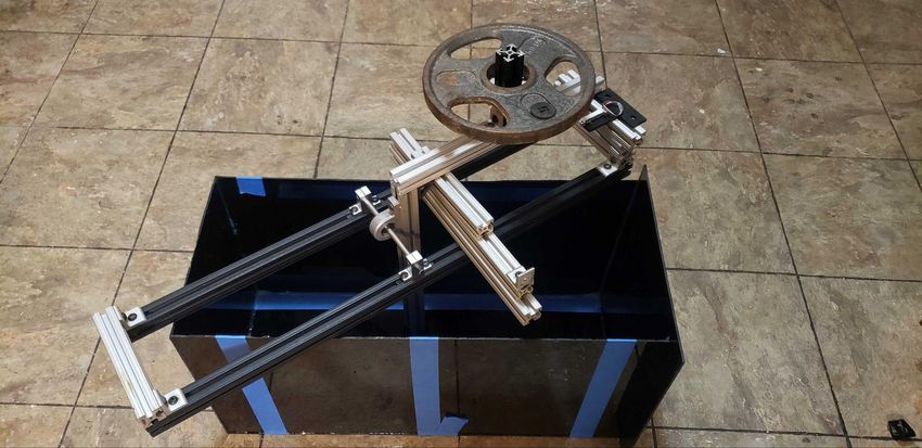
Mechatronics                                                                           2 of 10

payload and software additions to expand             Since Pico is smaller than previous
the AUV’s capabilities.                          designs, an I/O Box was included at the rear
                                                 of the AUV to increase the available surface
                                                 area for pass-throughs. Pico’s 0.25” thick
                                                 end cap design includes multiple flat
                                                 surfaces for the possibility to add additional
                                                 O-ring sealed cable pass-throughs or attach
                                                 supporting external payloads in future
                                                 designs. Figure 3 demonstrates the tight
                                                 configuration needed to fit all nine
                                                 pass-throughs for the connections that travel
                                                 from the outside to the inside of the AUV.
        Fig. 2: CAD model of Pico.

A. Mechanical Systems

    This AUV consists of a 3” diameter by
11.75” length clear tube as our hull. Our
original design consisted of using ABS
plumbing tube, to reduce cost, but as a proof
of concept vehicle we used cast acrylic tube      Fig. 3: End cap with cable pass-throughs.
to facilitate waterproof and component
testing. With an overall footprint of 15” by         Another inclusion of modularity and
10” and with a fully assembled weight of         accessibility in Pico’s design is the variety
approximately 8 lbs, this is our smallest        of 3D printed components. By using the
AUV to date. Two end flanges were fitted to      capabilities of additive manufacturing, our
either side of the housing tube, with double     designs of the external motor mounts were
O-ring seals that secure the ends and provide    efficient and simple. Our external frame,
mounting support for both our modified           which secures around our cylindrical
endcap and our 0.25” flat acrylic window.        housing, contains various features that
The purpose of having a modified endcap is       ensure we have the best placement of our
to increase the maximum number of cable          thrusters (Figure 4). Also featured is a small
pass-throughs to our system, from seven to       extrusion centered at the top, which assists
nine. While two access points in our AUV         with the alignment of the motor mounts by
are available, only the rear flange will be      sliding into a T-Slotted framing rail.
used to access the interior. The purpose of
having only one sizable access point is to
facilitate the removal of internal components
and to expedite troubleshooting. This is
further supported by the quick disconnect
feature of our internal support structure. The
overall symmetric shape and addition of our
buoyancy tray facilitates buoyancy control
by keeping the center of gravity close to the            Fig. 4: 3D printed motor mount.
center of the vehicle.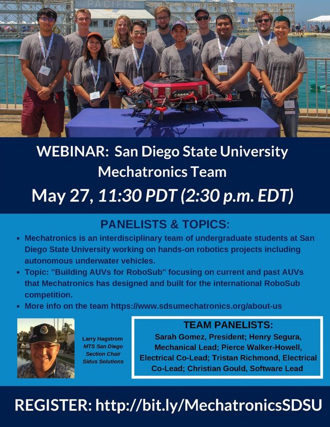
Mechatronics                                                                            3 of 10

                                                      The Electronic Speed Controllers (ESCs)
    With such a small volume accessible to        were placed near the rear of the vehicle,
our electronics, an internal frame was            allowing for shorter wire connections to the
necessary to maximize our space. Our              outside motors. Additionally, the ESCs were
internal frame provides sections for              arranged to face the same direction to assist
mounting electrical hardware, securing            with disconnecting them when removing the
batteries, and sliding space for camera           end cap. The Inertial Measurement Unit
adjustments. With a mostly 3D printed             (IMU) was placed behind the FPV camera to
frame supported horizontally by four              avoid noise interference from the ESCs.
aluminum standoffs, this frame allows for         Once the ESCs and other external
quick access to all of our electronic             connections are disconnected, the system
components and wiring without needing to          can be separated from the flange and worked
disassemble the structure. A new internal         on separately.
frame with different mounting holes can be
made in the event that the electrical design is
modified.

                                                       Fig. 6: Internal electrical layout.

                                                         A key design idea that the
                                                  mechanical team wanted to approach with
                                                  Pico was the use of compliant mechanisms.
                                                  A compliant mechanism is a flexible
                                                  mechanism that achieves force and motion
      Fig. 5: Pico’s internal structure.
                                                  transmission    through     elastic   body
                                                  deformation. 3D printing components made
    For vision, a Caddx Mini FPV CMOS
                                                  it much easier to fabricate compliant parts
camera was adapted into our system. Its
                                                  than our past builds. Our motor arms
small footprint and wide 160° field of view
                                                  incorporate   a    spring-like compliant
allows Pico to openly view anything directly
                                                  mechanism that will help absorb the shock
ahead. The placement of our electronic
                                                  force in the case of a collision. When
components was carefully considered and all
                                                  simulated using Finite Element Analysis
constraints were taken into consideration.
                                                  (FEA), each spring arm could deflect
For a better weight distribution, our battery
                                                  approximately 3 pounds of force each
was placed toward the front of the vehicle,
                                                  (Figure 7).
counteracting the heavy cable pass-throughs
in the back. The motherboard and Raspberry
Pi 4 were positioned with ample space on
either side to facilitate wire management and
simplify the process of disconnecting the
system. Figure 6 indicates that there is
ample space for a secondary battery,                  Fig. 7: Compliant motor arm (left),
although currently, our system only supports            displacement analysis (right).
one.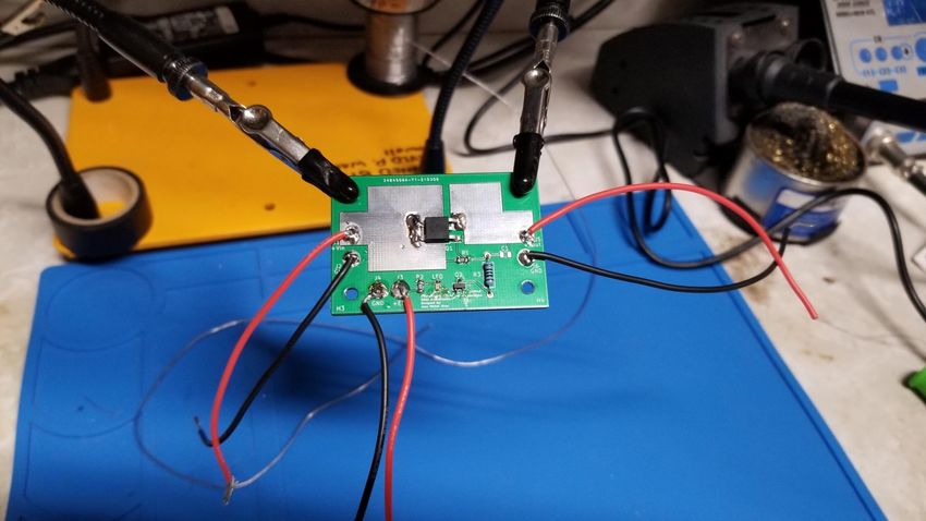
Mechatronics                                                                           4 of 10

        Another example of a compliant           the vehicle's center of gravity with the
mechanism used in our system is the off/kill     addition of external payloads. This would
bistable switch [1]. This switch, when lifted,   guarantee our control system calculations
detaches a neodymium magnet from the top         would be optimal regardless of any changes.
of the end cap, which in turn disconnects the    Adhesive foam was placed in the interior of
magnetic proximity sensor, turning off the       the motor mounts to counteract rotational
system completely. Using a bistable              forces caused by the motors, and to ensure a
configuration (Figure 8) gives us the option     tight fit.
to either push or lift the arm to one of two
positions.                                       B. Electrical Systems

                                                        The electrical system for Pico was
                                                 designed with the objective to build a small,
                                                 inexpensive, and easily reproducible system.
                                                 The system also serves as a minimalistic
                                                 platform for teaching new, incoming
                                                 members the essential building blocks of an
                                                 AUV’s electrical system, without the
  Fig. 8: Bistable kill switch (off position).   complexity of multiple PCBs.
       Our four vertical and two horizontal
motor configurations allow our system six
degrees of freedom (Figure 9). The vertical
arm mounts were placed near the bottom of
the vehicle to allow for complete
submersion when placed into the pool.
Additionally, the shroud design improves the
flow of water when used in either reverse or
forward thrust configuration.
                                                           Fig. 10: Pico’s electrical system
                                                                block diagram.

                                                         Therefore, our electrical system
                                                 design is centered around a single
                                                 motherboard PCB, which handles the
                                                 majority of the electrical operations. This
                                                 includes     sensor     data    acquisition,
                                                 communication with the computer, battery
                                                 monitoring, power management, and the kill
          Fig. 9: Top view of Pico.              switch.
                                                         With the budget friendly and size
       A three-piece motor arm connection        constraints in mind, the team decided to
allows for modularity and adjustability on       incorporate small and inexpensive sensors
the AUV. Subsequently, any motor mount           into Pico’s electrical system. The various
would be able to move either forward or          sensors on the AUV include: Blue Robotics
backwards to accommodate any changes to          Ultra High Resolution 10m Depth/Pressure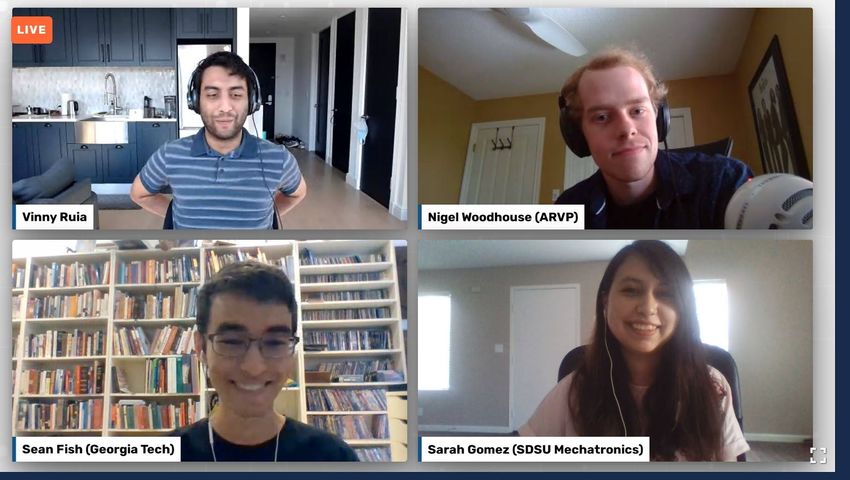
Mechatronics 5 of 10
Sensor, Adafruit BNO055 IMU that a battery must be swapped out and also
implements on-board sensor fusion for the verifies if the cells are depleting nominally.
specific force, angular rate, and temperature Additionally, a 50A PMOS power
data, TE Connectivity KMZ10CM magnetic switch is connected between the battery and
proximity sensor for magnetic proximity thrusters for physical engagement and
detection, and a Caddx Turbo Eos2 camera. disengagement of power to the actuators.
The power switch is a safety critical system,
both for the protection of the vehicle, as well
as team members working near the vehicle.
Power to the thrusters can be cut at any
moment through software or manually via a
magnetic proximity sensor. This adds a
double redundancy for cutting power to
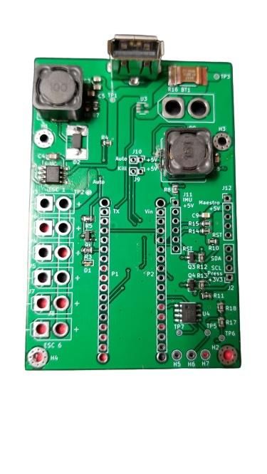
Fig 11: AUV’s main PCB layout. Pico’s thrusters. The power switch is
designed to be able to limit inrush current
The power from the two-cell LiPo and adjust turn on speed with a single
(7.4V) battery is regulated through two buck capacitor and resistor. The optimal value for
converters on the main PCB. The converters these components is found by estimating the
provide 5V at 3A and 5V at 2A outputs in capacitive load value during testing and
order to power the main computer as well as solving eq.1 for required capacitance value
all peripheral sensors. [3].
A battery monitor circuit is also
included on the main PCB. Voltage and
current measurements of the LiPo battery
provide real-time power monitoring of the
system, which is useful feedback. This
feedback can be used to optimize the
Controlling the inrush current
vehicle's operation with respect to power
increases the reliability of the electrical
consumption. For example, optimal control
system and provides a strong foundation for
algorithms, using the feedback, can be
all other subsystems. An incorrect design for
designed to maximize longevity of
high in-rush current leads to unwanted
operation.
power fluctuations at boot up time which
can impact functionality of the system and
decrease lifespan of critical components.
For the diver operator to safely
disengage power to the thrusters, as well as
control when the vehicle enters autonomous
mode, a magnetic proximity sensing system
is employed to physically communicate with
Fig 12: PMOS power switch validation the vehicle. When the kill mode is activated,
board. the electrical system sends an enable low
Battery monitoring is also a safety signal to the power switch circuit and cuts
feature. It notifies the vehicle operator when power.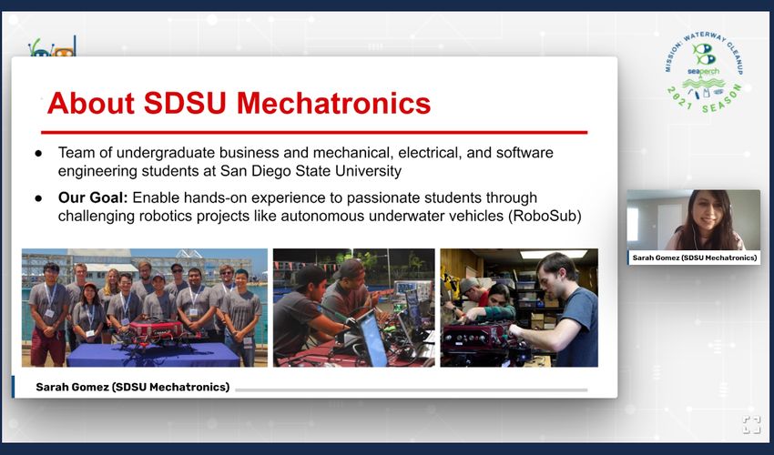
Mechatronics                                                                            6 of 10

        The magnetic proximity sensor, a          subsystems that are highly parameterizable
KMZ10CM, is a linear magnetoresistive             and easy to test. These systems run
sensor with very low hysteresis and high          independently of each other and have been
sensitivity. The proximity sensor is              containerized by Docker. Each system is
constructed from a small integrated circuit       built around a standard structure, that
(IC) chip which is used to trigger the sensor     institutes a gRPC (Google RPC) server, that
on and off. For reliable operation of the         executes a number of methods inside the
vehicle, the operator is able to switch           relevant subsystem.
between inactive state and autonomy mode
by utilizing the external autonomy magnet
baton. Additionally, the diver operator uses
the magnetic proximity sensor to detect the
unkill state, and uses the autonomy magnet
to toggle between the autonomy and inactive
state.

C. Software Systems
                                                      Fig. 13: High-level software system
        This year's software architecture was
                                                                   diagram.
aimed at creating a design that can handle a
more embedded style of development, while                 The primary system is called the
also lending itself to a fast turnaround of its   Intelligence subsystem (ITS) (Center Figure
system design. Each subsystem integrates to       13). The ITS is the main interface to the
each other through higher level software that     vehicle. All commands and telemetry flow
is consistent throughout. From a project          here to be distributed to the other
management perspective, this is particularly      subsystems, or out of the sub, to the
useful when delegating tasks to members. A        Graphical User Interface (GUI). The two
member can take up a part of the design, and      tertiary systems are the Inference Subsystem
make major development, or experimental           (IFS) (Left Figure 13) , and the Control
modifications. Because all the components         Subsystem (CTS) (Right Figure 13).
are particularly modular, we can swap out                 The IFS is a set of processes that run
design elements as necessary. This is also        computer vision algorithms, and send
useful from a system standpoint. Since each       computer vision telemetry, and video to
element is removable, if something is             other areas of the AUV or to the GUI. This
failing, we can easily restart or stop that       is possible by configuring the ITS to spin up
element before it causes issues.                  any single variant of the ITS. Certain
        The software system is developed          variants send data only to the Main GUI,
primarily in Python because of its simple         and some variants send only telemetry to the
syntax which lends itself to produce              ITS.
prototyping designs. All lower level and                  The specific algorithms running on
repetitive software is compiled in either C or    the IFS include OpenCV's tracking module,
C++ with Python wrappers for use within           and Tensorflow lite’s           MobileNetv3
higher level code.                                architecture. This system is implemented on
        The software architecture of the          the Raspberry Pi 4 and is directly connected
system is divided into multiple separate          to the vehicle’s camera system.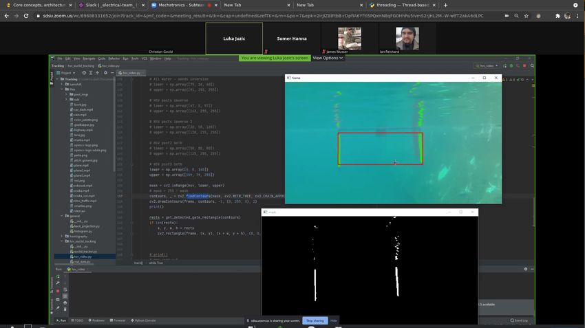
Mechatronics 7 of 10
IV. EXPERIMENTAL RESULTS
This year, due to challenges set by
COVID-19, including restrictions and
limited access to our equipment and testing
pool, Mechatronics achieved less physical
testing than desired. To circumvent these
challenges, individual components were
tested for the mechanical and electrical
systems.
The mechanical team also relied
heavily on simulations and engineering
calculations to ensure that the 3D printed
Fig. 14: Computer vision subsystem. frames and components were validated. FEA
was utilized to optimize the motor arms
The CTS is a set of processes that (Figure 15) and to increase the load
run the control system for the vehicle. This capacity to prevent yielding or breakage on
system can be switched between three main impact. Additionally, Solidworks was used
variants. The first variant is a manual debug to analyze mass properties and ensure that
mode, which takes control input from a the AUV is buoyant while keeping the
gamepad and directs it to the thrusters. The center of gravity below the center of
second variant is a learning mode, where the buoyancy.
control system monitors user movements
with the remote control, and learns better
feedback. The last variant is a competition
mode, where the feedback is directed
through the control system to intelligence
and directly to the thrusters.
There are two other architecture
subsystems that are not dockerized. The first
is the Operating System (OS), which is a
Fig. 15: Alternate motor arm configurations
highly modified version of Alpine Linux.
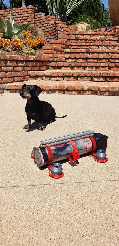
This OS contains only the necessary The team is also in the process of
applications for running Docker and the thruster testing. A testbench has been built
sensors. The other is the Sensor Subsystem to map the force vs. speed of six
(SNS), this architecture subsystem is built Readytosky 2300KV brushless motors. The
onto the OS. The SNS is a simple driver system uses a 500g strain gauge in
with high priority to communicate to the conjunction with a SparkFun Load Cell
Arduino that it is ready for more data. The Amplifier HX711 to measure the output
SNS has one of the higher priorities on the force of thrusters at different speeds [4].
OS, second only to the CTS. Additionally, this testbench configuration
can measure force output in forward and
reverse thrust orientation. This test results in
a math model of the thrusters to develop an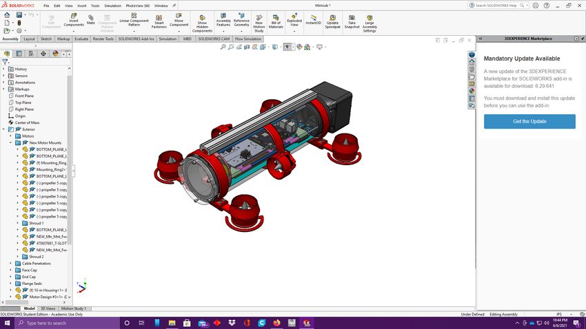
Mechatronics                                                     8 of 10

accurate and precise control system to be
utilized with our AUV [2].

          Fig. 16: Thruster testbench.

         For the electrical system, a PCB
procedure was implemented to validate the
functions of the motherboard. The procedure
includes checking the output wattage and
stability of voltage regulator outputs,
verifying that the battery monitor’s current
sense and voltage monitor works as
expected, testing that the max junction
temperature does not surpass the safe
operating area, and checking the voltage
drop over the PMOS switch to ensure
voltage is similar to theoretical voltage drop.

         IV. ACKNOWLEDGMENTS

    The Mechatronics team would like to
thank the SDSU Engineering Department as
well as our corporate sponsors: Leidos,
Northrop Grumman, Altium, Solidworks,
Nordson, and BrainCorp. We would also
like to thank our faculty advisor Theresa
Garcia and Donovan Geiger for supporting
the team.

                   VI. REFERENCES
[1]    Maker Resources. Compliant Mechanisms. (n.d.).
    https://www.compliantmechanisms.byu.edu/maker-resources.
[2] Abdelmalek Laidani, Mohamed Bouhamida, Mustapha
    Benghanem, Karl Sammut, Benoit Clement. A Low-Cost Test
    Bench for Underwater Thruster Identification. Conference on
    Control Applications in Marine Systems, Robotics, and
    Vehicles, Sep 2019, Daejeon, South Korea. hal-02306783
[3] ON Semiconductor. (n.d.). (tech.). Using MOSFETs in Load
    Switch Applications.
[4] Jehangir, R. (2014, August 6). Thruster Test Stand. Blue
    Robotics. https://bluerobotics.com/thruster-test-stand/.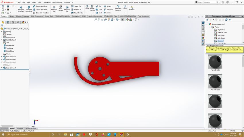
Mechatronics                          9 of 10

Appendix A: Component Specifications
Mechatronics                                                                     10 of 10

Appendix B: Outreach Activities              approach used for designing our RoboSub
                                             vehicle with competing SeaPerch teams and
    Mechatronics strives to      actively    public attendees.
participate  in   Science,   Technology,
Engineering, and Math (STEM) outreach,
and to promote education in STEM in the
San Diego community and beyond.

                                                Fig. 19: Panelist discussion at SeaPerch.

      Fig. 17: Panel flyer for SD Marine
       Technology Society meeting.

    This year, our outreach events were
limited to virtual activities due to
COVID-19. Our team participated in a panel
with the San Diego chapter’s Marine
Technology Society to demonstrate our
RoboSub vehicles.

      Fig. 18: SeaPerch university panel.

      Mechatronics was also represented at
the RoboNation university panel during the
2021 SeaPerch competition, in which our
team shared our systems engineering
You can also read