European GNU Radio Days 2019
←
→
Page content transcription
If your browser does not render page correctly, please read the page content below
European GNU Radio Days 2019
       17-18 Jun 2019
         Besancon
                        France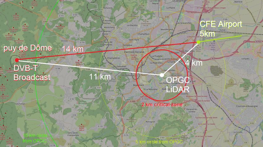
Table of contents

 Array signal processing optimization in GNU Radio for tracking and receiving
 applications, Bieber E [et al.]                                              1

 SatNOGS: Towards a Modern, Crowd Sourced and Open Network of Ground
 Stations, Julien Nicolas                                            4

 A Software Defined Radio 802.11 Infrared Transmission System, Joumessi
 Steve [et al.]                                                         6

 Study of the use of a SDR Passive RaDAR for the safe outdoor operation of
 an atmospheric LiDAR, Peyrin Frédéric [et al.]                          8

 Fully Digital Electronics for Fiber-Link Frequency Transfer Implemented on
 Red Pitaya, Cardenas-Olaya A. C. [et al.]                                  10

 VLBI with GNU Radio, RFNoC and White Rabbit, Boven Paul                    11

 Phase noise & digital noise: what is it and why it is important for ground-
 breaking RF-applications., Bourgeois Pierre-Yves                            12

 Frequency locking a laser on a spectral hole pattern with a multi-channel
 heterodyne method using SDR and GnuRadio, Galland N [et al.]              13

 A 60GHz digital link with GNU Radio and USRP radios, Boeglen Herve         15

 Embedded and Connected Receiver System for nano-satellite in Low Earth
 Orbit (LEO), Spies Francois [et al.]                                   17

                                      1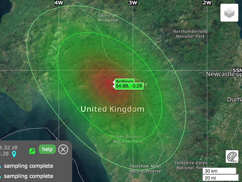
Using GNU Radio to do signal acquisition and analysis with Scopy, Suciu
Adrian                                                                  19

Embedded GNU Radio running on Zynq/PlutoSDR, Goavec-Merou Gwen-
hael [et al.]                                                   20

KiwiSDR as a new GNURadio source, Mayer Christoph                      22

Using GNU Radio Companion to improve student understanding of signal
processing theory through VHF Omni-Directional Range (VOR) signal de-
modulation, Blais Antoine [et al.]                                    24

A LoRaWAN Security Assessment Test Bench, Claverie Tristan [et al.]    26

List of participants                                                   29

Author Index                                                           30
Array signal processing optimization in GNU Radio
       for tracking and receiving applications
      E. Bieber1 , C. Campo1,2 , L. Bernard1 , H. Boeglen2 , S. Hengy1 , J.-M. Paillot2
      1
        French-German research institute of Saint-Louis (ISL), Saint-Louis, France
              2
                Université de Poitiers, XLIM, UMR 7252, Poitiers, France

                                                  Abstract

       Among other missions the French German research Institute of Saint-Louis (ISL) works on array
    signal processing for secured communications between high speed projectiles and allied base stations.
    Within that framework, a projectile tracking receiving station based on commercial Software-Defined
    Radios (SDR) was developed using four channels to steer an antenna array and recombine the received
    signals, hence improving the gain of the receiving station. A transmitter embedded in the projectile
    sent data to the developed receiving station at a 2 Mbits/s. In order to decode and process in real
    time the data received by the four channel antenna array, a high sampling rate was required. As this
    highly resource consuming application resulted in sample overflows that is, in periodic losses of data
    between the SDR and the computer, an optimization of our algorithms computed on GNU Radio and
    the communication between our blocks proved to be necessary.
       This paper intends to provide feedback on our optimization work. Some of the main problems we
    encountered and the solutions we propose to solve them are briefly exposed and will be further detailed
    in our oral presentation.

1    Introduction
Among other missions, the ISL works on develop-
ing secure communications between fired projectiles
and ground stations for future smart ammunitions.
Antenna arrays then offer many advantages such as
directional radiation patterns that can be dynam-
ically reconfigured to follow a moving transmitter,
fight against hostile jammers or listeners, etc. In
this context a SDR-based receiving station was de-
veloped using GNU Radio and the commercial Uni-
versal Software Radio Peripherals (USRPs) sold by
National Instruments, and proved to be able to elec-
tronically follow a transmitter by steering a four
element Uniform Linear Array (ULA), increasing
                                                             Figure 1: Flowgraph runnable at 1MS/s but creat-
the gain on the received signal. However in order
                                                             ing data overflows at 8.33MS/s.
to simultaneously decode the transmitted signal at
a 2 Mbits/s baud rate, the sampling rate for all
channels needed to be raised to 8 MSamples/s. To
compose with the SDR requirements it was neces-
sary for our laptop to receive data at a total rate of         Fig. 1 exhibits a flowgraph that managed to
33.33 MS/s (for all four channels), process the re-          perform projectile following at 1MS/s but created
ceived data with our implemented algorithms such             data overflows when higher sampling rates were re-
as beamforming and direction finding (DOA) that              quired. The important number of streams and use
were introduced in [1], and record the whole in real         of loops instead of vector oriented library kernels
time, resulting in a highly data consuming applica-          (Volk) were partly responsible for these overflows.
tion. Our first attempt to run this application with
a laptop equipped with an Intel i7 processor, 32                This paper does not focus on our application and
GB of RAM and a Samsung 850 evo SSD resulted                 results, but intends to present our work on code
in data overflows, i.e. in periodic data losses due to       optimization, especially to extend the computation
the lack of computation power, hence forcing us to           efficiency of our algorithms and flowgraphs devel-
think carefully about computation efficiency when            oped in C++ in GNU Radio [2]. The remaining of
implementing our application in GNU Radio.                   this abstract briefly covers suggested improvements
                                                             we have explored to avoid overflow issues.

                                                         1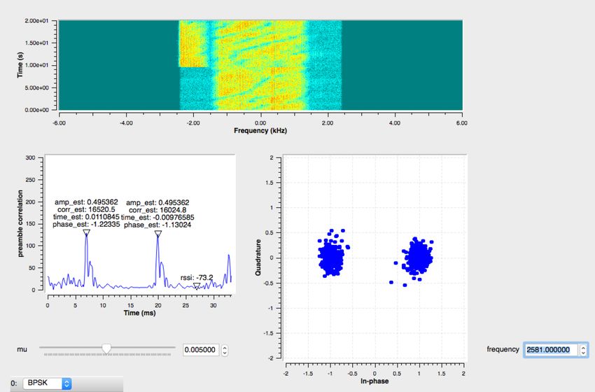
2    Suggested improvements for                        tion will allow GNU Radio threads to have prior-
                                                       ity over concurrent threads. Finally blocks using
     optimization                                      computationally heavy algorithms like DOA esti-
                                                       mation, etc, can be bound to a dedicated proces-
The first and most obvious question that arises is sor core while less demanding threads are bound
the network throughput between the SDR and the to a pool of remaining cores. It can be noted that
laptop, as well as the laptop capability to record all sometimes splitting such blocks into several ones
the needed data fast enough. In the case of our ap- will take advantage of the multi-core environment.
plication, the total 33.33MS/s sampling rate forced
us to install a Thunderbolt 2 SANLink adapter. It
can also be useful to create a RAMDisk if the drive
is not capable to record fast enough. Reducing the
amount of written data will have a positive effect
on the bitrate: users should write binary files rather
than ASCII ones and use data types with smaller
memory size.
   Once it is sure network throughput and data
recording speed are not the bottlenecks that cre-
ate data overflows, one can investigate his source
code to enhance his application efficiency. Due to
GNU Radio’s way of processing streams as buffers
of data, the work() method of a block is usually a
two-level loop that parses each sample of each input
stream. One should avoid multiple computations             Figure 2: Flowgraph runnable at 8.33MS/s.
of invariant values inside loops, but also try to use
optimized functions such as memcpy() or the Volk          Fig. 2 shows an optimized version of the previous
library [3] kernels instead of these loops whenever flowgraph that can be run on the same laptop at
possible.                                              8.33MS/s with a graphical view of the four received
   However even if correctly managing streams be- signals.
tween blocks allows to spare resources, it remains
important to limit those streams when they are ex-
pendable. Although it might be tempting as a fast 3          Conclusion
implementation to simply add a stream to a block
                                                       This paper presents the main modifications we
as a trigger or a way to share a variable between
                                                       brought to our developed blocks, making our ap-
blocks, it is computationally expensive and can be
                                                       plication runnable for four channels at a 8.33MS/s
responsible for data overflows when high sampling
                                                       sampling rate. An alternative communication vec-
rates are required. In order to efficiently communi-
                                                       tor between blocks that fits some of our particular
cate information between blocks, GNU Radio na-
                                                       needs has been mentioned, and all the suggested
tively offers the possibility to tag existing streams
                                                       improvements presented above will be further de-
with metadata. Since a tag is associated to a sam-
                                                       tailed in our oral presentation.
ple of a data buffer, we can consider tags as a syn-
chronous communication vector. For asynchronous
communication GNU Radio allows blocks to send References
messages to other blocks. A message is a 1 to N
communcation carried out by the sender: the re- [1] C. Campo, L. Bernard, H. Boeglen, S. Hengy,
ceiver message handler is called for each pending          J.-M. Paillot, Software-Defined Radio system
message. As no native option is given for users            for tracking application, EuCAP London 2018.
to develop blocks that can asynchronously use a
shared variable, we developed a new communica- [2] GNU Radio 3.6.4.2 C++ API documen-
tion vector based on static variables that allow vari-     tation at https://www.gnuradio.org/doc/
ables to be read and written by several blocks in          doxygen-3.6.4/index.html
a thread-safe way assured by a mutex. Further [3] Vector              Optimized      Library    of    Ker-
details on our proposed communication vector be-           nels (Volk) doxygen documentation at
tween blocks will be given in our presentation.            libvolk.org/doxygen/
   After information communication between blocks
has been verified enabling real time scheduling op-

                                                    2
SatNOGS: Towards a Modern, Crowd Sourced and
          Open Network of Ground Stations
        Manolis Surligas1,2 , Matthaios Papamatthaiou1 , Ilias Daradimos1 , Vasilis Tsiligiannis1 ,
 Pierros Papadeas1 , Agisilaos Zisimatos1 , Fredy Damkalis1 , Kostis Triantafillakis1 , George Vardakis1,2 ,
                               Nestoras Sdoukos1,2 , Nikos Karamolegkos1,2
                      1
                        Libre Space Foundation, Athens Greece, info@libre.space
                          2
                            Computer Science Department, University of Crete

                                                    Abstract

        Over the last years the launching cost of a payload in space has been significantly reduced and this
     trend is expected to continue, as the interest for space applications is increasing. The reduced launch
     cost and the advancements in technology, gave the opportunity to small satellites to revolutionize access
     to space.
        The majority of the small satellites missions are targeting the Low Earth Orbit (LEO). Due to the
     nature of this particular orbit, communication with a satellite is possible only for a few minutes per day
     for a given location. This raises the need for multiple ground stations in several geographic locations.
     Although such an infrastructure is possible, most of the times it is both complicated and expensive for
     research or educational entities to obtain. Given the fact that each ground station exhibits a small per
     day utilization for a specific satellite, the idle time can be used for reception of other missions.
        SatNOGS is an open source software and open hardware project that addresses this problem by
     interconnecting all participating ground stations, offering their idle time to other users of the SatNOGS
     network.

1     Introduction                                           able ground stations, while allowing the owner of
                                                             a ground station to have complete control over
SatNOGS is a global network of satellite ground              her hardware. The SatNOGS Database (DB)[1]
stations, designed as an open source participatory           is responsible for keeping the orbital elements and
project that receives data from Low Earth Orbit              communication related information of each satel-
(LEO) satellites. This particular orbit provides the         lite. It also holds decoded frames from the de-
ground station with a reception window that is lim-          ployed ground station network. The Data Ware-
ited to a few minutes. Therefore, a ground sta-              house, visualizes graphically the gathered data from
tion remains underutilized and idle for most of the          each satellite using a web interface and the Grafana
time. On the other hand, using a single ground               visualization framework. Last but not least, the
station means that there are only a few communi-             SatNOGS Ground Station is the necessary software
cation windows to send or receive data from a LEO            and hardware, that allows satellite tracking, the
satellite each day.                                          control of the RF front-end, signal reception and
   The concept of SatNOGS, is to use the deployed            demodulation of possible data frames.
ground stations around the world in an efficient
manner so that both the underutilization of them as
well as the coverage problems can be resolved with           2.1    The network
a single solution. Aground station operator join-
ing the SatNOGS network, provides the idle time       The SatNOGS Network[2] infrastructure is the
of their ground station to other users, while at the  backbone of the SatNOGS ecosystem and instru-
same time they can take advantage of ground sta-      ments essential functionalities for the flawless, effi-
tions at various locations of the earth to schedule   cient and effective operation of the entire project.
observations.                                         The network infrastructure services can be divided
                                                      into two main categories, the back-end and the
                                                      front-end. At the back-end, the SatNOGS Network
2 Architecture                                        keeps track of the available online ground stations
                                                      and the list of the observation jobs that each one
The SatNOGS ecosystem consists of several com- has been assigned. Moreover, it receives observa-
ponents operating interchangeably. The SatNOGS tion data from the deployed ground stations. The
Network infrastructure orchestrates the schedul- received data are either stored in the network in-
ing of each ground station, based on the trajec- frastructure to be used through the web interface
tory of the targeted satellites and the online avail- or are submitted to the SatNOGS DB[1] for fur-

                                                         1
ther analysis. The front-end of the SatNOGS Net-             The software on its core is written in C++, us-
work provides a set of different web interfaces. For         ing also some Python bindings. The first task of
the ground station operators, a web-based control            this module is to receive the signal from the SDR
panel is available in order to control and configure         front-end, apply coarse filtering and re-sample it.
remotely their stations. It also allows operators to         The later is crucial in order to reduce the sampling
schedule                                                     rate of the signal originating from the SDR device,
                                                             so the processing can be performed in CPU lim-
                                                             ited devices like the Raspberry Pi 3. Afterwards
2.2    Rotator hardware                                      and based on the satellite trajectory, the gr-satnogs
SatNOGS Rotator is the mechanism that allows                 compensates the Doppler effect which introduces a
tracking of satellites in both azimuth and elevation         constantly changing center frequency offset. Then,
axis. By design, the goal of the rotator is to keep          the Doppler corrected signal passes additional and
the cost low, by using widely available materials of         more fine grained filtering stages. Finally, the mod-
common sizes and 3D printed parts. For the users             ule tries to automatically demodulate the resulting
that cannot afford a rotator, SatNOGS can still op-          signal in real-time, based on the coding/modulation
erate without one, using a less directional antenna.         scheme of the targeted satellite. At the same time,
                                                             the module produces a waterfall spectrum analysis
                                                             plot and an audible representation of the spectrum.
2.3    Client software                                       The waterfall plot is an excellent tool, for imme-
                                                             diate and visual spotting of satellite transmissions,
The SatNOGS Client[4] is a Python program that               nearby interference, possible RF performance issues
runs on the ground station computer. The client              or misconfiguration at the station setup. The audi-
is responsible to retrieve observation jobs from the         ble transformation of the spectrum, is a technique
network and execute them. When a new job is re-              quite popular in the amateur community and many
ceived from the network, it is placed in an execu-           amateur signal analysis tools utilize it. For each
tion queue, sorted in chronological order based on           observation, the decoded frames, a waterfall spec-
the start time of the satellite pass. The client con-        trum analysis plot and the audio file are uploaded
stantly monitors the local time of the ground sta-           back to the SatNOGS Network, for visualization
tion and the starting time of the first observation at       and further analysis. Currently, gr-satnogs pro-
the queue. When the timing is proper, the client re-         vides automated demodulators decoders that cover
moves the observation job from the queue and pre-            a wide range of satellite missions. From beacons to
pares to execute it. To do so, it initializes the SDR        weather pictures.
front-end with the RF parameters described by the
job and then executes the appropriate GNU Radio
script provided by the gr-satnogs OOT module[3].             3     Conclusion
Meanwhile, the client controls the rotator, so the
antennas can track the trajectory of the targeted            The use of gnuradio enable an unmatched agility in
satellite. When the observation job is finished, the         a groundstation network. The ability to demodu-
client instructs the rotator to place the antennas in        late virtually any kind of transmission is fully future
a park position. Then, all the resulting files gener-        proof. It only requires automated software update
ated by the grsatnogs OOT[3] are uploaded back to            of the client. It is also the perfect match with low
the network. The client continues to operate, wait-          cost SDR receiver like rtl-sdr.
ing for the execution of the next job in the queue.
                                                             References
2.4    Gnuradio OOT module
                                                     [1] SATNOGS Database : https://db.satnogs.
Each ground station is equipped with an SDR de-          org/
vice for the signal reception. The architecture is
modular enough, so it can support a wide range of [2] SATNOGS network :         https://network.
different SDR hardware, depending on the target          satnogs.org/
cost of the station. For example, there are stations [3] gr-satnogs   :      https://gitlab.com/
using an RTL SDR dongle costing about 15USD,             librespacefoundation/satnogs/gr-satnogs
whereas others utilize a high-end device like the
USRP B210 with a cost of 2000USD. For the signal [4] SATNOGS client :            https://gitlab.
analysis and demodulation, the GNU Radio Out-of-         com/librespacefoundation/satnogs/
Tree (OOT) module called gr-satnogs [3] is used.         satnogs-client

                                                         2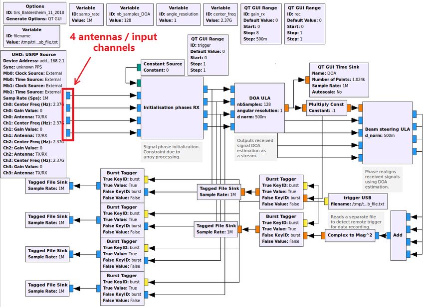
A Software Defined Radio 802.11 Infrared
                    Transmission System
    S. Joumessi-Demeffo,H. Boeglen,S. Sahuguede,P. Combeau,D. Sauveron,L. Aveneau,
                                 A. Julien-Vergonjanne
          CNRS, XLIM UMR 7252, F-87000 Limoges & F-86000 Poitiers, France

                                                  Abstract

        We present a 802.11 infrared packet transmission system built around GNU Radio and homemade
     infrared front-ends. The communication system is validated by a demonstration of audio transmission.

1     Introduction                                          with the design challenges involved, we found it
                                                            practical and efficient to develop our solution using
Optical wireless transmission is of great interest in       the SDR technology and in particular with USRP
many critical environments due to the confinement           radios and GNU Radio. Indeed, the GNU Radio
of optical beams (higher level of security) and the         platform already provides a large library of digi-
lack of interference of existing radio frequency con-       tal communication blocks and allows implementing
nections. This is particularly true for aeronautical        rapidly design modifications in software. One can
contexts. As part of the Aircraft Light Commu-              find several research works dealing with the im-
nication (ALC) project (European project Clean-             plementation of the 802.11 standard for SDR ap-
Sky2 H2020), our goal is to design a multi-user             plications. These implementations are focused on
optical communication system in an aircraft cock-           RF communications. As far as optical communi-
pit. Since the brightness inside the cockpit must           cations are concerned one can find several Visible
be greatly reduced during the critical phases of            Light Communications (VLC) implementations fo-
flight, the visible band is not appropriate. There-         cused on the 802.15.7 standard. The rest of this
fore, the optical wavelengths in the infrared (IR)          paper is organized as follows. Section 2 discusses
domain are used.One of the most successful IR stan-         the main characteristics of the developed communi-
dard (IrDA) is not applicable due to small oper-            cation chain. Section 3 presents an infrared packet
ating distance and the need for directed Line-Of-           transmission system using homemade IR front-ends
Sight (LOS) links with strong alignment. Because            before concluding in Section 4.
of growing interest in visible light communications,
there is today a lot of activities on optical wire-
less communication standards. This includes differ-         2    Communication chain
ent groups such as IEEE802.11bb, IEEE802.15.7r1,
IEEE802.15.13, and the ITU G.vlc. We decided to             The developed chain uses the classical MAC/PHY
follow the IEEE 802.11 standard and adapt it to our         layer model. We focus in particular on the trans-
study using IR technology. To enable interoperabil-         mission and the reception of packets for the LLC
ity with the 802.11 radio-frequency standards that          sub-layer and the frames of the IR PHY physical
dominate the market and thus facilitate light com-          layer.The LLC sub-layer is, among others, in charge
munication penetration, the future standard should          of building 802.11 compliant packets. One can find
be as close as possible to existing 802.11 specifica-       an existing GNU Radio transmission chain which
tions.Particularly in the ALC project, the interop-         includes this compliant packet forming scheme [1].
erability of the system with the 802.11 standard            The 802.11 compatibility can be verified by using
is important because it guarantees a system evo-            the network analyzer tool Wireshark. The LLC
lution and the ease of adaptation of this system            blocks are: WIFI MAC in charge of the packetiz-
to the future 802.11bb standard. The standardiza-           ing operation at the transmission side and WIFI
tion effort consists of the data link control layer         PARSE MAC in charge of the packet analyze at
(subdivided into two sublayer namely: the Logical           the reception side. The packetizing operation has
Link Control (LLC) and the medium access con-               the structure presented in Fig.1.
trol (MAC)) and physical (PHY) layer.We choose                 The WIFI PARSE MAC block is able to distin-
a multi-step work: firstly we implement the On-             guish and list the different fields of the received
Off-Keying (OOK) modulation which is one of the             packet. In the Bloessel implementation [3], the
most used modulations in optical wireless transmis-         block in charge of this operation is part of the
sion systems, and second we will study other mod-           OFDM physical layer. This is the reason why we
ulations used in 802.11 versions. In order to cope          could not use it in our IR PHY implementation and

                                                        1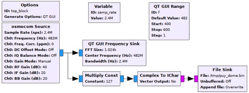
of IR technology, the link has to work in base-
                                                    band (OOK,L-PPM modulations). To comply with
                                                    this requirement, Ettus LFTX and LFRX daugh-
                                                    terboards have been selected as they allow com-
                                                    munications between 0 and 30MHz. The designed
        Figure 1: IR PHY packet structure.          TX IR front-end converts the LFTX board voltage
                                                    ranging between 0 and 3.3V to a 0-100mA current
                                                    into the IR LED thanks to a high speed video op
had to develop a MAC packet data unit (MPDU) amp. The role of the RX front-end is to convert
Parse block. This block is in charge of recovering the very low PIN photodiode current (in the order
the payload.The LLC sub-layer packets are then of 1uA) into a voltage value of around 1V. This is
aggregated in a frame compliant with the 802.11 accomplished by a special type of op amp called
IR PHY standard specification [2], shown in Fig.2. a transimpedance amplifier (TIA).The demonstra-
This is a starting point because this specification tion is made of two parts: first, we send a file from
is no longer present in the latest versions of the the IR transmitter and analyze the frame received
standard. One of our goals is to adapt it to the at the receiver side using Wireshark. Secondly, a
constraints of the ALC project.                     user directly speaks in a microphone connected to
                                                    the PC of the IR transmitter and it is possible to lis-
                                                    ten the sound recorded by the computer connected
                                                    to the IR receiver.

         Figure 2: LLC packet structure.                    4    Conclusion
   We have worked with the available GNU Radio              As part of the H2020 ALC project we are devel-
tutorials and documentation. We have developed              oping a multi-user infrared system for communica-
a PHY Formatter block dealing with the insertion            tions in a cockpit. To ensure scalability, the sys-
of the synchronization fields and the transmission          tem should be as close as possible to the 802.11
header forming a frame. The Parse PHY block at              standard currently under development for optical
the reception side analyzes the frame and returns           wireless communications. Our approach is based
the length field to the Demux Header/Payload                on the implementation of an 802.11 packet trans-
block which then demultiplexes the header and the           mission system developed with GNU Radio, tested
payload. For simplification reasons, as a first step,       with USRP radios including specifically manufac-
we fix the time slot value to the bit time instead of       tured optical front-ends. Currently, our system is
8s as specified in the 802.11 IR standard. Us PHY           able to transmit 802.11 packet data with an OOK-
layer implements an OOK modulation by adding                modulated PHY IR. Our future work will focus on
an offset to the BPSK modulation scheme. This               the integration of other modulation schemes such
offset is required by the IR front-ends. OOK mod-           as OFDM used in 802.11 a/p/n and the implemen-
ulation is one of the most used in wireless opti-           tation of the DCF access method.
cal communication systems.The main GNU Radio
tools for packet communication systems design are
the tags and the messages.These tools use polymor-          References
phic type (PMT) data. Several blocks of our chain
use PMT. For example the convolutional code ECC             [1] B. Bloessl et al., ”Towards an Open Source
block specified by the 802.11 standard, the packe-              IEEE 802.11p stack:       A full SDR-based
tizing blocks WIFI MAC, WIFI Parse, PHY For-                    transceiver in GNU Radio,” 2013 IEEE Vehicu-
mater, PHY Parse and Header/Payload Demux.                      lar Networking Conference, Boston, MA, 2013,
                                                                pp. 143-149.

3    Front-ends & demonstration                             [2] Wireless LAN Medium Access Control (MAC)
                                                                and Physical Layer (PHY) Specifications p1491
The 802.11 PHY IR specification recommends data                 2012.
rates of 1 Mbps and 2 Mbps. In a multi-user con-
                                                         [3] H Boeglen, Steve Joumessi-Demeffo, et al.. Op-
text, it is essential to have a high data rate to ensure
                                                             tical front-ends for USRP radios. French GNU
good communications of all users. For that pur-
                                                             Radio Days 2018, Jul 2018, Lyon, France.
pose, we designed RX and TX front-ends [3] hav-
ing a 10MHz bandwidth. Due to the constraints

                                                        2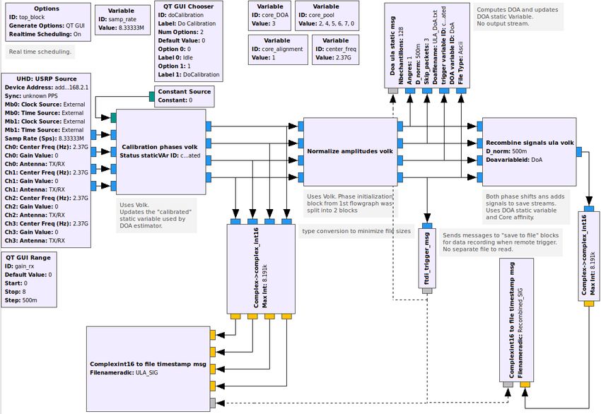
Study of the use of a SDR Passive RaDAR for the
safe outdoor operation of an atmospheric LiDAR
F. Peyrin1 , J.-M. Friedt2
1
OPGC, UMS 833 CNRS, Univ. Clermont Auvergne, Aubière, France
2
FEMTO-ST, UMR 6174 CNRS, Univ. Franche-Comté, Besançon, France
March 28, 2019
Abstract
Our project aims to evaluate the potential of the Software Defined Radio technology associated to
GNU Radio ecosystem in order to propose new and pragmatic solutions when applied to scientists
needs, thus bridging the gap between engineering and research points of view. Here, we study the
ability for a passive RaDAR to detect aircrafts and allow safe operation of a LiDAR.
1 Introduction
The OPGC [1] is an Observatory of Earth Sciences
dedicated to Volcanology and Physical Meteorol-
ogy. Among instruments implemented, a LiDAR
helps to characterize the composition of the atmo-
sphere in aerosol particles.
The LiDAR activity requires compliance with in-
ternational air traffic regulation [2]. Due to strong
Laser emission, the potential ocular hazard for the
pilots must be cancelled by stopping the Laser emis-
sion while an aircraft is flying over the critical zone Figure 1: LiDAR location and critical zone.
of the LiDAR. Usually, air traffic safety is provided
by a X-band pulsed radar determining the presence
(position, altitude, speed) of any aircraft entering We used GNU Radio to acquire and save DVB-T
the vicinity of the LiDAR. signal (Fig. 2) echoed by the moving distant target.
On the one hand, a first alternative solution has
been developed based on acquiring and processing
ADS-B frames transmitted by the IFR aircrafts [3].
On the other hand, we also study and present here
the potential of a passive RaDAR solution based
on J.-M. Friedt previous work [4] using an existing
non-cooperative source.
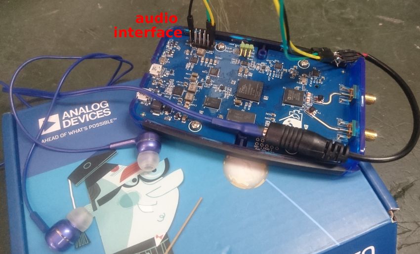
2 Experimental setup Figure 2: GNURadio code for DVB-T acquisition
Experimental setup involves the reception of echoes Then, using MATLAB (MatWorks), we post-
of the local Terrestrial Digital Video Broadcasting processed these data by autocorrelation to find the
(DVB-T) source reflected by cabin’s aircrafts. The transmitted signal, delayed in time, so shifted in
LiDAR and receiver are located (Fig.1) on the roof frequency by Doppler shift.
of the OPGC, 420 m above sea level, 4 km away
from the airport and 11 km from the Puy de Dôme,
1465 m asl., where is located the DVB-T emitter. 3 Results
The receiver hardware configuration was based
on a RTL-SDR USB stick that features the Realtek Several tests have been processed (available at [5]).
RTL2832U chipset and the R820T2 tuner specifi- Among these, a measurement at a bistatic distance
cally designed for use in SDR mode. We used this of 10 km (Fig.3), which is sufficient compared to the
broadband receiver coupled to a UHF yagi antenna critical zone, suggests the ability to detect aircraft
to acquire DVB-T broadcast at 482 MHz. flying up to ten thousand meters above our LiDAR.
1be complementary for operational purpose if hard-
ware is upgraded and calculation time is lowered.
More generally, SDR implementation may also
be helpful for further Earth Science Experiments
driven at the OPGC, in particular when applied to
remote sensing instruments. For example, Software
Defined Radio could also be dedicated to passive or
active RaDAR concepts involved in characteriza-
tion of atmospheric clouds or volcanic ash plumes.
The main technical objectives are to improve the
ergonomics and the mobility of instruments on the
field, to improve the spatial and temporal resolu-
tions (size and movement of the targets), to reach a
greater modularity (emission-reception, directions,
frequencies ...), and to optimize the overall cost
Figure 3: Remote detection (a.u.) of the target, of development and maintenance of these new sys-
circled with red, at a bistatic distance of 10 km, i.e. tems. This ongoing study will be focused on free
an aircraft at a distance of 5 km in a configuration and open source ecosystem such as GNURadio.
where source, receiver and target are aligned.
References
The DVB-T emitter provides promising results
that need to be confirmed with a suitable hardware, [1] at http://wwwobs.univ-bpclermont.fr/
i.e. two synchronized receivers fed by directional
antennas, one pointing to the transmitter (reference [2] Doc 9815 AN / 447 2003 of the Inter-
signal) and an other one pointing to zenith to de- national Civil Aviation Organization, 2003
tect eventual mobile targets (surveillance channel). at https://www.skybrary.aero/bookshelf/
Separating the reference and monitoring channels books/3849.pdf
improves the signal-to-noise ratio and, more im- [3] Tests of the ADSB-SDR technique to detect
portantly, eliminates artifacts related to autocor- aircrafts - An alternative to radar solution
relations of signals due to multiple targets. for air traffic safety during Lidar activity,
The main limitation currently observed is the F. Peyrin et P. Freville, 2018 at https:
processing time of the acquired signals. In the ab- //www.researchgate.net/publication/
sence of any optimization (arbitrary choice of 221 329874059_Tests_of_the_ADSB-SDR_
processed points, for a Doppler shift analyzed by technique_to_detect_aircrafts_-_An_
steps of 5 Hz between -400 and +400 Hz), and alternative_to_radar_solution_for_air_
post-processing the acquired data with an inter- traffic_safety_during_Lidar_activity/
preted language (GNU / Octave), two minutes are
needed to process every second of recording. With- [4] RADAR passif par intercorrélation de sig-
out considering a processing shorter than the ac- naux acquis par deux récepteurs de télévision
quisition time, the main effort, in addition to the numérique terrestre, J.-M Friedt, 2018 at http:
experimental setup, must focus on the reduction //jmfriedt.free.fr/passive_radar.pdf
of this computation time, highly parallelizable and [5] RADAR passif pour la sécurité d’opération
optimizable in terms of choice of the parameters of d’un LiDAR, F. Peyrin et J.-M Friedt,
analysis. Towards the aim of real time processing, Experiment Findings, 2018 at https:
shifting part of the processing chain from general //www.researchgate.net/publication/
purpose Central Processing Units (CPUs) to FPGA 331929425_RADAR_passif_pour_la_
parallel computing units is being developed [6]. securite_d%27operation_d%27un_LiDAR/
[6] J.-M Friedt, W. Feng, S. Chrétien, G. Goavec-
4 Conclusion, Perspectives Merou, M. Sato, Passive radar for measuring
passive sensors: direct signal interference sup-
This study highlights the potential of the SDR con- pression on FPGA using orthogonal matching
cept in regard to our applications. While detecting pursuit, accepted SPIE Multimodal Sensing and
ADS-B with a dongle could already give an inex- Artificial Intelligence: Technologies and Appli-
pensive solution for air traffic safety during LiDAR cations (München, 2019)
activity, the passive RaDAR implementation could
2Fully Digital Electronics for Fiber-Link Frequency
Transfer Implemented on Red Pitaya
A. C. Cardenas-Olaya, E. Bertacco, S. Micalizio, C.E. Calosso
INRIM, Torino, Italy
Abstract
1 Introduction
1VLBI with GNU Radio, RFNoC and White Rabbit
P. Boven
JIVE, Netherlands
Abstract
1 Introduction
1Phase noise & digital noise:
what is it and why it is important for
groundbreaking RF-applications.
P.-Y. Bourgeois
FEMTO-ST, Time&Frequency dpt, UMR 6174 CNRS, Besançon, France
Abstract
For more than a decade, digital electronics has a massive impact on about every research field offering
flexibility, robustness and reconfigurability.
1 Introduction form such characterizations within the GNU Radio
context.
Numerous developments of complex scientific in-
strumentation now employ routinely partial or fully
digital systems, inherited from telecommunications References
and Software Defined Radio (SDR).
Within the framework of Time & Frequency [1] B P Abbott & al. Characterization of tran-
metrology, it has become challenging in the devel- sient noise in advanced LIGO relevant to grav-
opment of modern sensitive instrumentation where itational wave signal GW150914. Classical and
quantization noise and signal noise paths take a sig- Quantum Gravity, 33(13):134001, jun 2016.
nificant place for qualifying ultrastable clocks, os-
[2] He-Shan Liu, Yu-Hui Dong, Yu-Qiong Li, Zi-
cillators, frequency transfer and timing systems.
Ren Luo, and Gang Jin. The evaluation
From Amateur Radio to VLBI (Very-long-
of phasemeter prototype performance for the
baseline interferometry), DSN (Deep Space Net-
space gravitational waves detection. Review of
works), LIGO(Laser Interferometer Gravitational-
Scientific Instruments, 85(2):024503, 2014.
Wave Observatory)[1], Evolved LISA(Laser Inter-
ferometer Space Antenna)[2], ACES (Atomic Clock [3] Gnu radio. gnuradio.org.
Ensemble in Space), . . . , it is worth to note that
some knowledge on instrumentation limitations and [4] Franz Franchetti, Tze Meng Low, Doru Thom
their proper characterization is of importance. Popovici, Richard M. Veras, Daniele G. Spamp-
Unfortunately there is a lack on handy design inato, Jeremy R. Johnson, Markus Püschel,
tools and techniques for complex designs leading James C. Hoe, and José M. F. Moura. Spiral:
to high computational efforts in programming and Extreme performance portability. IEEE special
prototyping that are ultimately greatly error prone. issue on From High Level Specification to High
Although a few of valuable libraries and software Performance Code, 206(11), 2018.
do exist (GNURadio[3], Spiral[4], liquidsdr[5]. . . ),
[5] Liquidsdr. liquidsdr.org.
they are currently not adapted to oscillator metrol-
ogy modeling (parametric noise simulations, vari- [6] P-Y Bourgeois, G Goavec-Merou, J-M Friedt,
ances, normalized spectra . . . ). and E Rubiola. A fully-digital realtime soc
Along the journey, I propose to present differ- fpga based phase noise analyzer with cross-
ent techniques and pitfalls in the measurement and correlation. In Joint EFTF/IFCS, pages 578–
qualification of the digital signal processing chain 582. IEEE, 2017.
kernel (Signal→ADC→DDC) commonly used in
every SDR environment[6, 7]. [7] B Marechal, A Hugeat, G Goavec-Mérou, G Ca-
bodevila, J Millo, C Lacroûte, and PY Bour-
Fourier
analysis
geois. Digital implementation of various lock-
ing schemes of ultrastable photonics systems.
DUT ADC
NCO
In 2018 IEEE International Frequency Control
DDC Symposium (IFCS), pages 1–4. IEEE, 2018.
Figure 1: Elementary digital processing chain for
oscillator metrology
I will also show how it is currently difficult to per-
1Frequency locking a laser on a spectral hole pattern
with a multi-channel heterodyne method using SDR
and GnuRadio
N. Galland1,2 , N. Lucic2 , H. Alvarez-Martinez2 , S. Zhang2 , B. Fang2 , R. Le Targat2 ,
A. Ferrier3,4 , P. Goldner3 , S. Seidelin1,5 , Y. Lecoq2
1
Université Grenoble Alpes and CNRS, Institut NEEL,
F-38042 Grenoble, France
2
LNE-SYRTE, Observatoire de Paris, Université PSL, CNRS, Sorbonne Université,
61 avenue de l’Observatoire 75014 Paris
3
Université PSL, Chimie ParisTech, CNRS, Institut de Recherche de Chimie Paris,
75005, Paris, France
4
Sorbonne Université, 75005, Paris, France
5
Institut Universitaire de France, 103 Boulevard Saint-Michel,
F-75005 Paris, France
Abstract
High precision spectroscopic probing of a narrow spectral hole pattern imprinted in the inhomo-
geneously broadened absorption spectrum of Eu3+ : Y2 SiO5 crystal can be used to stabilize a laser
frequency. A multi-hole pattern can be burn and all the holes can be probed simultaneously using a
multiple frequency signal. The dispersion induced dephasing acquired by the light through the crystal
is measured to derive an error signal suitable to lock the laser frequency to the spectral hole pattern.
An Ettus USRP X310 driven by a python program based on GNU Radio is used for both generating
the multiple frequency signal and to compute the correction applied to the laser frequency.
1 Introduction 2 Experimental setup
Frequency stabilization of ultra-stable lasers is typi- To ensure the possibility of spectral hole burning,
cally realized using high finesse optical Fabry-Perot the europium doped yttrium orthosilicate (Eu3+ :
cavities (FPC) that can provide a stability of a few Y2 SiO5 ) crystal is maintained at a cryogenic tem-
10−16 at about 1 s integration time. However, re- perature, typically between 3.2K and 4K, in a com-
cent development concerning optical lattice clocks mercial close-cycle cryostat with vibration isola-
appear to require lower frequency noise at this time tion.
scale to obtain the best performances of the clock.
Eu3+:Y2SiO5
A new direction of development for laser stabi-
ML x2
lization relies on spectral hole burning. The spec- PD2
T=4K
tral pattern imprinted in a rare earth doped crys- PDH Cavity Lock
PD1 1.952 GHz
tal at cryogenic temperature is expected to show
higher stability than the brownian motion limited AOM
FPC [1], [2]. double
Frequency Comb pass
LPF LPF
The spectral hole burning technique relies on two 8 MHz
physical processes occuring in Eu3+ : Y2 SiO5 crys-
tals. First, the initially narrow 7 F0 → 5 D0 transi- USRP
X310
tion of Eu3+ is, due to inhomogeneities in the host Offset
PLL
SL x2
crystalline matrix, broadened from 120 Hz for an
isolated ion to approximately 2 GHz. Secondly, at
cryogenic temperatures, a narrow linewidth laser Figure 1: Schematics of the experimental setup.
can excite some ions to metastable levels with a The GNU Radio flowgraph is driving the USRP to
lifetime that can reach tens of days at 4 K. By do- generate multi frequency signal for AOM and com-
ing so, the absorption is saturated around the laser puting the correction applied to the offset of the
frequency and a hole is created in the absorption PLL from the two RX signals
spectrum that can be use as a frequency discrimi-
nator for laser stabilization. A two-laser optical system is used to burn and
1then probe the spectral hole. The master laser at 4 Conclusion
1160 nm is pre-stabilized to a high finesse FPC. An
offset phase-lock loop is used to servo the slave laser The double-hole based detection has improved a lot
at 1160 nm to the master laser with a controlled the detection noise of the detuning induces disper-
offset frequency (typically 980 MHz). Both lasers sion. Indeed, the previous detection scheme using
are independently frequency doubled to reach 580 only one hole was exhibiting a noise level compati-
nm, the center of the broadened transition 7 F0 → ble with a stability in the low 10−15 at 1 s. The new
5
D0 . The slave laser is then sent to a double-pass scheme shows a detection noise compatible with a
AOM to generate an arbitrary spectral pattern in stability in the mid 10−16 at 1 s.
the light (in the 1 MHz range around the center We then infer that the residual instability of the
frequency). Both yellow lasers are then spatially laser when locked to the spectral hole is not due
overlapped and the resulting beam is splitted in to the detection noise of the setup, but to other
two channels, one going through the crystal and to technical issues. Next imporvement will be to re-
a 2 GHz bandwith photodiode, the other directly duce the thermal fluctuation of the sample holder
to an identical photodiode for reference. in the cryostat and the residual vibration due to
the working cycle of the pulsed tube. An investiga-
The beatnote obtained on each photodiode is de-
tion to find the optimal spectral pattern will also be
modulated to 8 MHz and amplified before acqui-
conducted to reach the low 10−16 at 1 s or below.
sition by the two RX channels of an Ettus USRP
This project has received fundings from Ville de Paris
X310. One TX channel is used to drive the fre-
Emergence Program, LABEX Cluster of Excellence FIRST-
quency offset between the two lasers. The other
TF (ANR-10-LABX-48-01), within the Program “Investisse-
TX channel is used to drive the double-pass AOM.
ments d’Avenir” operated by the French National Research
The GNU Radio flowgraph is on the one hand de- Agency (ANR), Région Ile de France; European Union’s
riving the error signal from the dephasing between Horizon 2020 research and innovation program under grant
RX channels induced by the spectral hole disper- agreement No 712721 (NanOQTech); ANR under grant
sion. A spectral mask is applied to band pass fil- number 14-CE26-0037-01 DISCRYS; EMPIR 15SIB03 OC18
ter the RX signal arround different frequencies and and from the EMPIR program co-financed by the Participat-
remove any unwanted spectral component. The a ing States.
proportionnal and integrator filter applied on the
error signal provides a correction modulating the
TX channel driving the offset frequency. On the References
other hand, another flowgraph is used to generate
an arbitrary spectral pattern applied to the AOM. [1] M. J. Thorpe, L. Rippe, T. M. Fortier, M. S.
Kirchner and T. Rosenband, “Frequency stabi-
lization to 6 × 10⁻¹⁶ via spectral-hole burning”,
Nat. Photon. 5, 688-693 (2011)
3 Results [2] D. R. Leibrandt, M. J. Thorpe, C.W. Chou, T.
M. Fortier, S. A. Diddams,and T. Rosenband,
An optical frequency comb stabilized on a state-of- “Absolute and Relative Stability of an Optical-
the-art ultrastable laser allows us to evaluate the Frequency Reference Based on Spectral Hole
stability of our laser over a timescale from 1 s to Burning in Eu3+:Y2SiO5”, Phys. Rev. Lett.
1000 s. We can therefore measure the stability 111, 237402 (2013)
of the laser pre-stabilized to our FPC to approx-
imately 10−14 fractional frequency instability at 1 [3] O. Gobron, K. Jung, N. Galland, K. Predehl,
s. R. Le Targat, A. Ferrier, P.Goldner, S. Sei-
By using a double hole pattern with one reference delin, and Y. Le Coq, “Dispersive heterodyne
mode (in a wide hole and so experiencing a small probingmethod for laser frequency stabiliza-
dispersion) and one signal mode (in a narrow hole, tion based on spectral hole burning inrare-earth
experiencing a big dispersion as a function ot the doped crystals”, Optics Express 25 (13), 15539-
detuning), we obtain a good frequency lock of the 15548 (2017)
laser on the narrow hole. The laser then exhibits
a stability in the low 10−15 for 1 s to 10 s time
scale. This result is almost one order of magnitude
better than the previous results obtained on this
experiment while using a single hole to derive the
correction signal [3].
2A 60GHz digital link with GNU Radio and USRP radios
H. Boeglen1
1
XLIM Laboratory, UMR CNRS 7252, Limoges, France
University of Poitiers
In this communication we present a 60 GHz radio link for Ettus USRP radios. The link is
built around dedicated integrated circuits from Analog Devices. The transmission chain is
validated with a 100Mbps OFDM system designed with GNU Radio.
Keywords: Millimeter wave communications, RF front-ends
1 Introduction firms provide this service for a relatively low cost.
For example, a lot of 10 pieces of 50 mm x 50 mm
Most Ettus USRP SDR equipments can be fitted FR4 4 layer boards would cost you about 50$ [1].
with RF daughter boards featuring different radio Up to a frequency of 10 GHz the PCB design
ranges and bandwidths. The maximum RF fre- process is relatively easy. But what about millime-
quency available for Ettus boards is currently 6 ter wave bands applications? As you may know,
GHz. Due to the overcrowded RF spectrum and to pushed by the 5G mobile telephony potential mar-
enable very high data rates (i.e. several Gbps) mil- ket, things are changing rapidly so that dedicated
limeter wave bands are being envisaged for 5G tele- ICs and suitable measurement equipment will be
phony. The forecasted bands are 26, 40 and 60GHz. easily available in the next few years. As far as mea-
Millimeter wave bands have specific characteristics surement equipment is concerned, the cost is defi-
which have to be evaluated in real transmission con- nitely going to be a problem for amateurs. Again,
ditions. It is therefore necessary to have measure- this problem can be overcome by the Software De-
ment equipments able to work in these bands. The fined Radio (SDR) technology. The only problem
goal of this paper is twofold. Firstly, to present the that remains is the availability of millimeter wave
constraints associated with millimeter bands and front-ends for off-the-shelf SDR hardware. It is
to look for existing solutions adaptable to USRP possible to build one using frequency mixers and
radios. Secondly, to design an affordable 60GHz gain blocks available from manufacturers like Mini-
transceiver solution based on available off-the-shelf Circuits but it is going to be bulky, costly and cur-
integrated circuits (IC). The rest of this paper is rently the maximum frequency achievable is 40 GHz
organized as follows. Section 2 presents the con- [2]. After some research, I found an interesting
straints associated with the design of printed circuit IEEE paper about an open source SDR frontend
boards (PCB) for millimeter wave radio communi- for the 60 Ghz band by Zetterberg et al [3]. Un-
cations. In section 3, a USRP based 60 GHz radio fortunately, the Hittite ICs they used have been
link is detailed and validated with the help of an phased out. In the meantime, Hittite was acquired
OFDM transmission chain built with GNU Radio. by Analog Devices (ADI). Frequently in the past,
Finally, section 4 concludes the paper by giving evo- I used to have several good ideas with no facilities
lution possibilities of the current demonstrator. to implement them, but was finally lucky to find
their realization by ADI. Again, I dreamt about a
60 GHz transceiver solution and ADI did it!
2 Electronics design con-
straints for millimeter wave
bands 3 A HMC6300/6301 60 GHz
link with USRP radios
In recent years, the design and the realization
of transceiver solutions up to about 6 GHz have The HMC6300/6301 Systems on Chips (SoC) from
been simplified by the availability of relatively low ADI are an evolution of the HMC6000/6001 from
cost dedicated chips and measurement equipment. Hittite. Their main characteristics are summarized
Moreover, the manufacturing of PCB even for more in Table 1. Figure 1 presents a block diagram of
than two signal layers is relatively easy and low the HMC6300 SoC. ADI provides an evaluation kit
cost. Nowadays, it is no longer necessary to be a for the HMC6300/6301 for about 3500$. This kit
member of a specialized firm or lab to take advan- allows the user to set up a half-duplex link but does
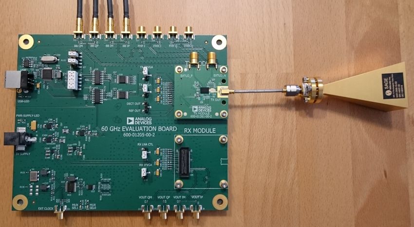
tage of RF PCB manufacturing. Several Chinese not include the antennas. In order to obtain a linkbudget of more than 100m we decided to fit the user designed boards like the 60 GHz evaluation
boards with 23dBi horn antennas from SAGE [4]. kit presented in this paper. We are currently work-
The total price of this setup is around 5700$. ing on a cheaper and a better integration of ADI 60
GHz SoCs with USRP radios. This requires the de-
sign of a PCB integrating an HMC6300/6301 eval
board and a 71.42857 MHz ECL oscillator circuit
needed by the HMC6300/6301 synthesizers. The
setup of the SoC transmission parameters (e.g. out-
put power, carrier frequency) is made via an SPI
interface which can be implemented with the avail-
able GPIO pins on the LFTX/RX or BasicTX/RX
daughter boards. The working testbench and its
evolutions will be presented at the European GNU
Radio Days in Besançon and the design files will be
Table 1: HMC6300/6301 specifications.
shared with the community.
The last operation to perform is to connect the
kit to the USRP radios. This is easily accomplished
thanks to LFTX/LFRX or BasicTX/BasicRX
daughter boards from Ettus. These boards can
transmit/receive baseband data to/from the eval-
uation board as long as the user provides a differ-
ential/non differential adapter (balun transformer
or Fully Differential Amplifier) to the IQ interface
of the HMC6300/6301. The testbench has been
successfully tested over a 100 m link with a 100
MSymb/s OFDM chain designed with GNU Radio.
The transmit power was set to 10dBm. Figure 2
shows a picture of the transmitter section. Figure 2: HMC6300 TX front-end fitted with
SAGE horn antenna.
References
[1] https://www.pcbway.com/
[2] https://ww2.minicircuits.com/homepage/
homepage.html
[3] P. Zetterberg, R. Fardi, Open Source SDR Fron-
tend and Measurements for 60-GHz Wireless
Figure 1: Block diagram of the HMC6300 SoC.
Experimentation, IEEE Access, Vol. 3, pp. 445-
456, 2015.
4 Conclusion
[4] https://www.sagemillimeter.com/23-dbi-
The daughterboard interface of N210 and X310 ra- gain-wr-15-v-band-rectangular-horn-ant
dios is quite generic and allows to easily connect enna/Embedded and Connected Receiver System for
nano-satellite in Low Earth Orbit (LEO)
F. Spies1,2 , S. Givron2
1
FEMTO-ST Complex Computer System, Montbéliard, France
2
Université de Franche-Comté, Montbéliard, France
Abstract
The objective of this work is to design a set of satellite signal reception, embedded, connected and low
power consumption. This set must be simple to implement with the ambition of being widely deployed
on a global scale to provide complete and continuous coverage so that each satellite transmission can
be received at any time without loss. The altitude of the satellite orbit must allow the planet to be
covered with less than a hundred reception stations on earth. The stations will be located mainly in
universities with an eduroam connection to facilitate the transmission of information on a server.
1 Introduction threshold and thus increases the reception distance.
One of the advantages of using software radio is
Communication systems with nano-satellites re- that it allows you to reconfigure the demodulation
main complex to implement. They must have a chain for each passage of a nano-satellite. There
suitable receiving chain in order to be able to pro- are software programs such as gpredict that inte-
cess small amplitude signals. The implementation grates the paths of all active in-orbit nano-satellites
altitude is around 500 km. The nano-satellite trans- to predict the path times.
mission chain must be as light as possible, includ-
ing the antenna, power amplifier and communica-
tion board. The objective of nano-satellites is to 3 Picsat Demodulation
be as light as possible with a reduced altitude to
limit the cost of placing them in orbit as much as Picsat, a specific nano-satellite put into orbit in
possible. Therefore, the ground station must be 2018, demodulated the signal transmitted in BPSK
able to compensate for the transmission and recep- 1200 baud. The demodulation chain performed by
tion constraints of nano-satellites. It is necessary to [1] integrated all the demodulation functions nec-
be able to amplify weak signals received with mo- essary to interpret the information transmitted by
torized directional antennas combined with power the satellite and send it back to the server central-
amplifiers. The objective of this work is to provide izing all the reception on the planet. Indeed, at
a ground-based reception solution consisting of a this altitude, the flight times of an area are gener-
simple omnidirectional antenna and a Software De- ally between 5 and 15 minutes. We understand the
fined Radio (SDR) interface. The advantage of ra- importance of being able to multiply the number
dio software is that it can receive several different of reception sites around the world in order to be
nanosatellite signals and can be reprogrammed at able to increase the exchange times with the nano-
any time. In addition, this solution can be updated satellite. If ground systems are connected to the
over time to adapt to changes in modulation in the Internet, it is possible to gradually move towards a
nano-satellites of next generations. Finally, a study permanent and continuous connection that would
of the dimensioning of the ground reception module limit the redundancy of data transmitted from the
will make it possible to reduce the unit cost so that satellite and thus increase its ability to transmit in-
a large-scale deployment can be envisaged. formation to the ground. All you need is between
80 and 100 ground receiving systems evenly dis-
tributed to be in permanent communication with
2 Demodulation Chain the nano-satellite. A maximum distance between
2 reception systems of about 3500 km (30 degrees)
The frequencies mostly used by these nano- would allow this continuity of communication.
satellites are VHF/UHF amateur radio frequen-
cies (145 and 435/438 MHz) or the S band (2.2 to
2.3 GHz). Modulations are generally of the FSK, 4 Systems Implementation
BPSK or GMSK type. Baud rates are generally
between 1200 and 9600 baud. The use of two sym- Before attempting to embed the receiving chain on
bols per period significantly reduces the reception low-cost electronic boards, it is preferable to vali-
1date oversized solutions to facilitate development. the restitution of the transmitted data. Software
Thus, we used a laptop computer, a Raspberry Pi 3, radios have a USB port and can only be connected
a Raspberry Pi zero and a microcontroller ESP8266 to the ESP8266 at a low speed equivalent to version
[2] including a Wi-Fi interface to perform the signal 1.0 or 1.1 of about 1Mbps. We have chosen to use
demodulation. The signal reception was performed the radio software in SDR-IP mode (Fig. 1), i.e.
with a USRP B200 mini, an ADALM-Pluto and an through a Wi-Fi/IP connection to validate the pro-
RTL-SDR. cessing capacity of the microcontroller. Data recep-
On laptops and Raspberry PIs that use a UNIX tion centered on the corrected frequency could be
system, the use of gnuradio is possible. On Rasp- completely integrated, in purely integer functions
berry PI boards, computing power is limited, the for more efficiency. In order to limit the energy
USB interface works in version 2 and the use of consumption by the entire station, it is only exe-
command line gnuradio is preferable. On the micro- cuted when a nano-satellite passes through and re-
controller, the program is downloaded from the Ar- mains in deep sleep between two passes. The times
duino development interface in C/C++/LUA lan- of the visits are obtained on servers located on the
guage. Internet.
5 Signal Generator
When designing a demodulation function, it is nec-
essary to decode a good quality signal, but this
is not enough. It is also necessary to be able to
measure the qualities and characteristics of the al-
gorithm designed to identify the potential of the
reception sensitivity threshold obtained. If the re-
ception sensitivity threshold is too high, decoding
will only be possible when the nano-satellite is near
the zenith of our position. If the sensitivity thresh-
old is low enough, decoding can be carried out up to
positions close to the horizon where the link budget
is most unfavourable. Figure 1: Global Architecture with the Wi-Fi mi-
We have produced several types of files con- crocontroller ESP8266.
taining signals including increasingly large atten-
uations and small constant, linear and polynomial
frequency shifts to gradually reproduce the Doppler
effect of LEO orbits. 7 Conclusion
Porting demodulation functions into a microcon-
6 Decoding Tests troller has allowed us to improve the overall effi-
ciency of the receiving chain. The Doppler effect
First, we validated that reception could be achieved correction remains to be integrated into the micro-
with an omnidirectional antenna placed horizon- controller to complete the demodulation chain. We
tally in the perpendicular of the satellite path finally chose to reintegrate the entire demodulation
connected to a USRP B200 mini interface. The functions into gnuradio to reduce processing time
whole thing was connected to a laptop PC with and use a low-power Raspberry Pi zero that easily
gnuradio/gr-picsat [1] to ensure sufficient comput- connects an SDR interface.
ing power and memory capacity. The reception
time is approximately 8 minutes out of a potential
10 to 12 minutes. This first result was considered References
sufficient to qualify the reception.
[1] PicSat telemetry parser added to gr-
In a second step, we validated the computing and
satellites at https://destevez.net/2018/01/
memory capacity of the Rapsberry Pi zero Wi-Fi
picsat-telemetry-parser-added-to-gr-satellites/
(ARM 1 core 1GHz 512GB RAM) to demodulate
the I/Q signals received in gnuradio/gr-picsat in [2] ESP8266: Wi-Fi microchip with full TCP/IP
command line mode. stack and microcontroller at https://en.
In a third step, the demodulation was coded di- wikipedia.org/wiki/ESP8266
rectly into the micro-code of the ESP8266 to allow
2You can also read