EVOLUTION OF CFD AS A TOOL FOR CHEMICAL ENGINEERING - RICHARD D. LAROCHE FLUENT INC.
←
→
Page content transcription
If your browser does not render page correctly, please read the page content below
Evolution of CFD as a Tool for Chemical
              Engineering

             Richard D. LaRoche
                   Fluent Inc.
          Lebanon, New Hampshire, USA

       CFD in Chemical Reaction Engineering IV
                    Barga, Italy
                     June 2005

             richard.laroche@fluent.com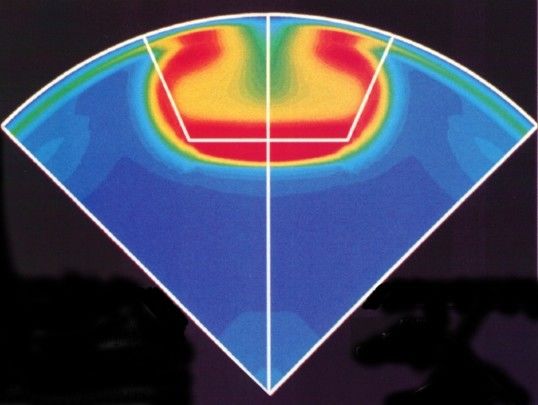
CFD in the Chemical Industry in the 90 s

          Early adopters
             Chemical Process CFD Users Group

          Early Struggles
             Geometry & mesh generation
             Affordable fast, compute resources
             Limited solver technologies

R.D. LaRoche , CFD in CRE IV
Barga, Italy, June 2005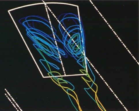
Chemical Process CFD Users Group
   North American group (1993-2000)

             3M                       Huntsman
             Air Products             LIGHTNIN
             Argonne National Lab     Mitsubishi Chemical-US
             (USDOE)                  NETL (USDOE)
             Bechtel                  Nalco Chemical
             BP Amoco                 FuelTech
             Chemineer                National Institute of
             Chevron                  Standards & Technology
             Cray                     (U.S. Dept. of Commerce)
             Dow Chemical             Phillips Petroleum
             Dow Corning              Procter & Gamble
             DuPont                   Rohm & Haas
             Eastman Chemical         Shell Oil -US
             Eli Lilly                UOP

R.D. LaRoche , CFD in CRE IV
Barga, Italy, June 2005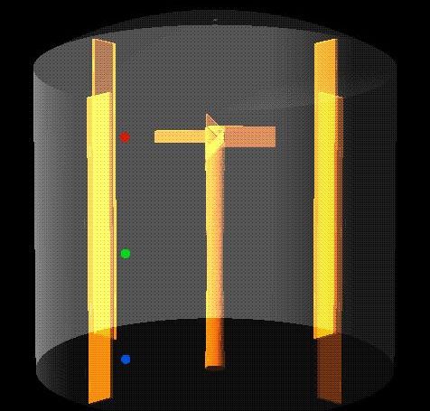
European CPCFD Users Group

  Roster from June 1998 Meeting in Munich

DSM Research, Netherlands                Aalborg University Esbjerg, Denmark
University College London, UK            Norwegian University of Science
Center for Advanced Studies, Italy       Technical University of Szczecin,
Bayer AG, Germany                        Poland
Unilever, UK                             ICI Chemical & Polymers, UK
CIRSEE Suez Lyonnaise des Eaux, France   Neste Oy, Finland
BP Chemicals, UK                         LIPE-GPI-INSA, France
LIPE-GPI-INSAT, France
Tel-Tek, Norway                          EniTechnologie, Italy
Schlumberger Cambridge, UK               BHR Group Ltd., UK
Performance Fluid Dynamics, Ireland      British Steel, UK
TU-Darmstadt, Germany                    Hoechst, Germany
Sintef, Norway                           Cray Research/Silicon Graphics
Bechtel, USA

R.D. LaRoche , CFD in CRE IV
Barga, Italy, June 2005
Examples

       Chemineer HEV Static Mixer
          Large Eddy Simulation (LES)
          Coefficient of Variation (CoV) Comparison with
          Experimental Data (Etchells, Wadley & Fasano, Mixing
          XVII, 1999)

       Stirred Tank
          Sliding Mesh & Multiple Reference Frame (MRF)
          Lagrangian Particle Tracking with Turbulent Dispersion
          Minye Liu (Procter & Gamble) and Clay Andreasen (Cray)
          Blendtime Comparison with Experimental Data (Grenville
          et al., BHRG, 1992)

R.D. LaRoche , CFD in CRE IV
Barga, Italy, June 2005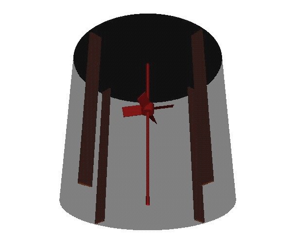
Chemineer HEV Static Mixer

Experimental work at Lehigh U.
(Gretta, et.al)

Steady-state k- (Bakker &
LaRoche, Mixing XIV, 1993)
Large Eddy Simulation (Bakker,      Photo Courtesy of Chemineer Inc.
1998 AIChE Annual Meeting)
LES with Experimental
Verification (LaRoche & Etchells,
Mixing XVII, 1999)
R.D. LaRoche , CFD in CRE IV
Barga, Italy, June 2005
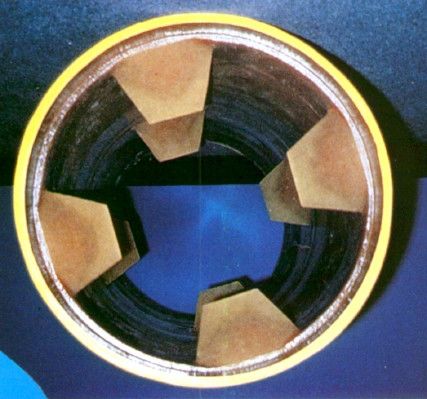
HEV Mixer: Steady-State CFD
                Bakker & LaRoche (1993)
     FLUENT v4.21
     400K cell structured grid
     k- turbulence model
     1/8 slide of 3D geometry
     9 CRAY C90 cpu hours

                                          Qualitative results
                                          Difficult to converge
                                          Unable to predict mixing
                                         performance quantitatively
                                          Attempts with RSM model
                                         were not successful
         Turbulent K.E. past first tab
R.D. LaRoche , CFD in CRE IV
Barga, Italy, June 2005
HEV Mixer: Large Eddy Simulation
LaRoche & Etchells (1999-2000)
Work inspired by LES work by Bakker (1998)
Follow-on work by Liu (2001-2002)
3-array HEV
Re~200000
Fluent v5
Unstructured Grid: 700-800K Tetrahedral Cells
LES model plus 2 species
100 timesteps
72 cpu-hours
18 wallclock hrs. (4 cpus)
Verification with Experimental Mixing
Performance Data
BHR Group, Cranfield, UK (1998-99)
R.D. LaRoche , CFD in CRE IV
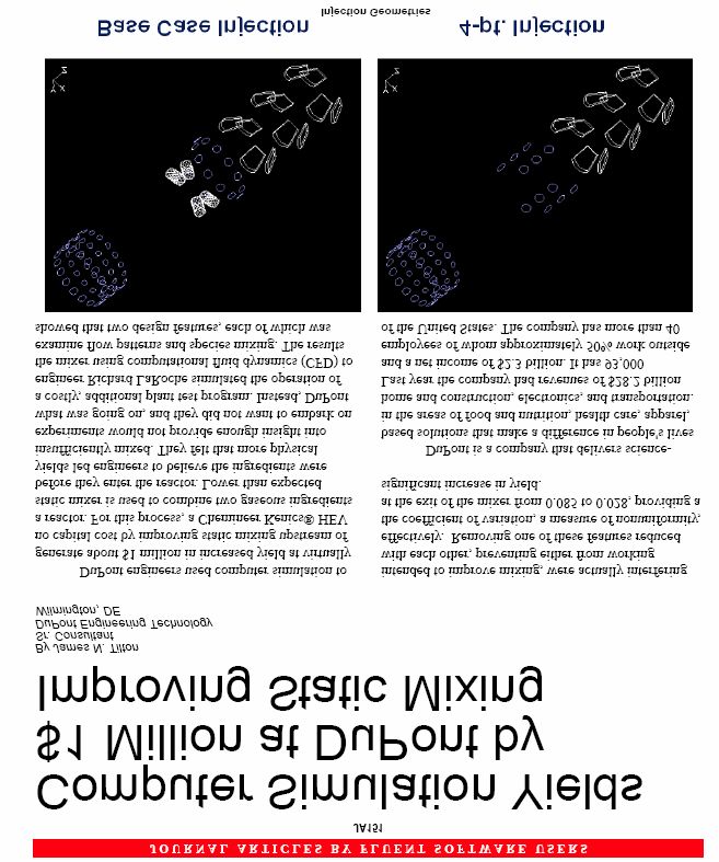
Barga, Italy, June 2005Effect of Gas Injection Scheme
Base Case Injection 4-pt. Injection
R.D. LaRoche , CFD in CRE IV
Barga, Italy, June 2005HEV Static Mixer - Trailing Vortices
Base Case Injection 4-pt. Injection
R.D. LaRoche , CFD in CRE IV
Barga, Italy, June 2005Axial Concentration Profiles
Base Case Injection
4-pt. Injection
Large diameter Inlets
4-pt. Injection
Small diameter Inlets
Note: Forney work used to size inlets
R.D. LaRoche , CFD in CRE IV
Barga, Italy, June 2005Trailing Vortices - 4-pt. Injection Cases
Large diameter Inlets Small diameter Inlets
R.D. LaRoche , CFD in CRE IV
Barga, Italy, June 2005Comparison with Experimental Data
Coefficient of Variation
n 2
1 i 1
xi x
CoV
x x n
Base Case Injection
Experimental CoV=0.085 - 0.099
Computational CoV=0.0810 ± 0.0050
4-pt. Injection
Experimental CoV=0.028 - 0.055
Computational CoV=0.0405 ± 0.0137
R.D. LaRoche , CFD in CRE IV
Barga, Italy, June 2005How Important Was This to DuPont? R.D. LaRoche , CFD in CRE IV Barga, Italy, June 2005
Stirred Tank Flow

  Sliding-mesh CFD became
commercially available in 1994-95
     STAR-CD
     FLUENT
     CFX
 Prior CFD analysis only qualitative flow
prediction
 Industrial collaboration to model time-
dependent stirred tank flow (R. LaRoche,
D. Choudhury, A. Bakker and CPCFD
Users Group, 1994-96)
 Dow Chemical Laser-Doppler
Velocimetry Data for 4-blade Pitched
Blade Turbine (Cassian Lee, 1994)

R.D. LaRoche , CFD in CRE IV
Barga, Italy, June 2005
Stirred Tank Analysis (circa 1993)
PBT/DT vs. PBT/PBT Configurations
(length and color by velocity magnitude in m/s)
R.D. LaRoche , CFD in CRE IV
Barga, Italy, June 2005Laminar Flow in a Stirred Tank
Velocity Field Comparison for Re = 20.4 ND 2
Re
R. D. LaRoche & D. Choudhury
MIXING XV - Banff, Alberta, Canada, June 18-25, 1995
R.D. LaRoche , CFD in CRE IV
Barga, Italy, June 2005Sliding-Mesh Stirred Tank Project
CPCFD Users Group 1994-96
Turbulent Stirred Tank Lab Stirred Tank Reactor
Re = 21505, N = 500 rpm, µ = 1 mPa s
FLUENT v4.31
0.8 cm
90° Tank Section
geometric symmetry (4 blades, 4 0.90 cm
14.5 cm
baffles) 0.70 cm (liquid Height)
5.08 cm
k- RNG turbulence model
70K Cells (38x37x49), Time-dependent 6.67 cm
1.25 cm
sliding-mesh
No-slip boundary condition at 14.5 cm
impeller, walls, baffles (tank ID)
Liquid surface modeled as flat slip Baffles: 4 at 90° apart
boundary Width: 1.25 cm
thickness: 0.3 cm
placed at the wall
Dow Chemical Laser-Doppler
Velocimetry Data for 4-blade Pitched Impeller: 4 blade, 45° PBT
blade width: 0.90 cm
Blade Turbine (Cassian Lee, 1994) thickness: 0.10 cm
diameter: 5.08 cm
R.D. LaRoche , CFD in CRE IV
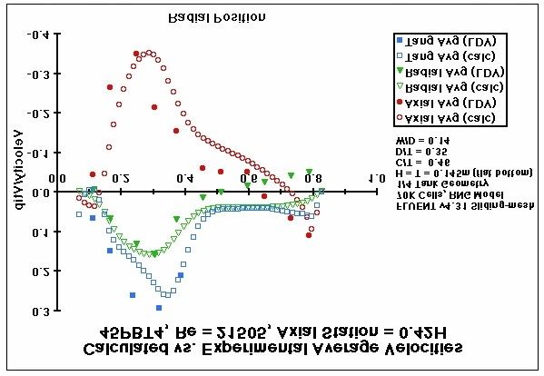
Barga, Italy, June 2005Dow Chemical STR - FLUENT Sliding-Mesh
Re=21505, RNG, 6 mm under 4-PBT in baffle plane
0.2
0.1
0
0.00
0.60
1.20
1.80
2.40
3.00
3.60
4.20
4.80
5.40
6.00
6.60
7.20
7.80
8.40
9.00
9.60
10.20
10.80
r = 7.2 mm
-0.1 r = 12.2 mm
r = 21.1 mm
-0.2 r = 26.5 mm
r = 36.3 mm
-0.3
-0.4
500 rpm
-0.5 1 cP
1000 kg/m3
-0.6
Time (s)
R.D. LaRoche , CFD in CRE IV
Barga, Italy, June 2005Velocity Vectors, Re = 21505 R.D. LaRoche , CFD in CRE IV Barga, Italy, June 2005
Sliding Mesh Stirred Tank: 1994 Statistics

  Geometry and grid generation
      person-weeks
  Startup Calculation Phase
      90 revolutions
      20 timesteps/revolution (timestep=6.0e-3 s)
      80-160 Cray C90 CPU hours
  Final Calculation Phase
      1 revolution
      90 timesteps/revolution (timestep=1.33e-3 s)
      4 Cray C90 CPU hours
  Comparison with LDV Data
      time-averaged velocities over 1/4 revolution (23 timesteps)

R.D. LaRoche , CFD in CRE IV
Barga, Italy, June 2005
R.D. LaRoche , CFD in CRE IV Barga, Italy, June 2005
Turbulent Stirred Tank Analysis
LaRoche, Liu & Andreasen (1999)
Flow & Turbulence
Fields computed by
MixSim1.0/Fluent 4.5
Multiple Reference Frame
(MRF), k- model
220K Cells, 1/4 Geometry
Setup in less than 1 hour
~8 cpu-hours
Lagrangian particle
tracing using
HyperTrace(tm)
~16 cpu-hours for 100K
particles traced for 50 sec.
Scalable parallel application -
2 wallclock hours on 8 cpus
R.D. LaRoche , CFD in CRE IV
Barga, Italy, June 2005Effect of Tracer Injection Location R.D. LaRoche , CFD in CRE IV Barga, Italy, June 2005
Stirred Tank Blendtime Comparisons
            500
                                                                      Variance - a1
            450                                                       Variance - a2
                                            Inj@2T/3 - 100K           Variance - b1
            400                                                       Variance - b2
                                                                      Variance - b3
            350                                                       Variance - b4
                                          [Experimental Data
                                          from Grenville,BHRG,        a1 exp
            300                                                       a2 exp
                                          1992]
 Variance

                                                                      b1 exp
            250
                                                                      b2 exp
            200                                                       b3 exp
                                                                      b4 exp
            150

            100

             50

              0
                  0   10   20   30   40   50     60     70       80    90   Time (sec)
R.D. LaRoche , CFD in CRE IV
Barga, Italy, June 2005
Power Number
Measure Effects of
Re, pitch/D, Dw/D,
C/D to get Po vs. Re
plots
Determined
experimentally or
using CFD
Analogous to the
friction factor in pipe
flow
P
Po
N 3D 5
R.D. LaRoche , CFD in CRE IV
Barga, Italy, June 2005Blend Time
How fast to get to
Homogeneity?
Measurements - Batch
Stirred Tank
Color Change - somewhat
arbitrary
Conductivity or pH -
approach to steady state
Acid/Base Indicator
Reactions
Approach to Average
Uniformity
95% approach (or 5% of k
steady state) c e
Extrapolation along
exponential decay curve
R.D. LaRoche , CFD in CRE IV
Barga, Italy, June 2005Blend Time Correlation
95% Mixing Time when c=0.05
k ln( c) k ln(0.05) 3k
Turbulent Mixing Correlation (Ruzkowski & Grenville)
Based on a wide range of impeller types and tank sizes
Quite a wide standard deviation for experimental results ± 30%
2
5. 4 T
N for Po1 3 Re 6404
Po1 3 D
Why is so much effort spent on predicting blendtime?
Not a particularly useful scale-up parameter
R.D. LaRoche , CFD in CRE IV
Barga, Italy, June 2005Usefulness of the Power Number
Estimate power imparted to the fluid by the impellers
Many engineers may use Power per Tank Volume as a
scale-up criterion
Better Approach: - local power/mass (not average)
In stirred tanks, use power per impeller swept volume for ballpark estimate
P Po N 3 D 5 Po N 3 D 5 Po
Assume N 3D 2 N 3D 2
V imp D2 D2
Dw D
4 4 4
Can be calculated directly from CFD
Local is an important parameter in solids breakup, gas
bubble breakup, mass transfer
R.D. LaRoche , CFD in CRE IV
Barga, Italy, June 2005Po Number - Effect of Mesh on Impeller Blade
# Name Total # Fluid Cells Mesh Type
1 hybrid 125936 90o Hybrid
2 hybrid-more-tets 213305 90o Hybrid
3 pure-tet-coarse 312781 360o Tetrahedral
4 pure-tet-fine 942117 360o Tetrahedral
5 pure-hex-coarse 85772 90o Hexahedral
6 pure-hex-fine 197560 90o Hexahedral
1 3 5
6
2 4
R.D. LaRoche , CFD in CRE IV
Barga, Italy, June 2005Power Numbers for Grid Dependence*
Case Computed NP % Error
Pure-hex-coarse 1.37 2.1
Pure-hex-fine 1.34 4.3
Hybrid-original 1.38 1.4
Hybrid-more-tets 1.36 2.9
Pure-tet-coarse 1.38 1.4
Pure-tet-fine 1.39 0.7
* Second order solutions, same solution scheme
R.D. LaRoche , CFD in CRE IV
Barga, Italy, June 2005Particle Statistics
Mammalian cell 4500
bioreactor
Link to experimental 4000
observations of cell
viability 3500
3000
Shed light on fluid 2500
environments that cells
experience at different 2000
scales
1500
1000
Opportunity to build
additional models with 500
particle tracking ODE 0
when flow can be
decoupled from cell
3
5
6
7
9
0
.9
.1
.3
.5
.2
7
4.
6.
8.
0.
2.
5.
2.
10
19
27
35
62
processes
14
22
30
39
47
55
Turbulent Dissipation Rate (m2/s3)
R.D. LaRoche , CFD in CRE IV
Barga, Italy, June 2005Can You Simulate My Reactor?
As engineers, why would we ask this question?
First we must develop which engineering
question needs to be answered
Then decide what level of physics modeling is
needed to answer the question
Do you need 1% accuracy or do you need
correct trends to choose between design
alternatives?
Build analysis approach in an incremental
fashion
R.D. LaRoche , CFD in CRE IV
Barga, Italy, June 2005We Can t Afford 3D Modeling, so We ll
Do 2D Anyway
Example: 2D stirred tanks?
Create more doubt from assumptions that it s worth
2D impellers & baffles?
Sympathize when there was a lack of (affordable)
compute power and parallel software
But maybe you should tackle the problem another way?
Extremely complicated physics with 2D models does
this make sense?
Need to solve 3D before you knew whether you could
justify simplifying to 2D!
Design situation may be 2D flow, but pathological
situation is 3D and/or transient!
Example: slot coating flow
How about 3D, transient and simplified physics instead?
Then you can add physics complexity as you go along
You are ever gaining insight
R.D. LaRoche , CFD in CRE IV
Barga, Italy, June 2005Let s jump in and solve this problem with CFD
We tend to get enamored with high-tech tools
that we forget our engineering sense
Still useful to attack problem first as if you only
had your calculator (or slide rule) and your
books
What are the standard design practices, theory
and correlations?
What are the known scaling rules?
R.D. LaRoche , CFD in CRE IV
Barga, Italy, June 2005CFD as a Production Engineering Tool
Enabling Technologies
Improved CAD tools
Automatic, unstructured meshing
Efficient, parallel software
Inexpensive parallel hardware
Better Physical Models
Multiphase
Reacting Flow and Micromixing
Population Balance Methods
But We Must Not Lose the Ability to Build In Complexity
Layer by Layer
R.D. LaRoche , CFD in CRE IV
Barga, Italy, June 2005Optimistic But Some Concerns
Compute Resources
Most Companies Do Not Have Large Centralized Compute
Facilities
Many Industrial Practitioners have access to small clusters
(less than 8 cpus)
Large Compute Clusters Need Adequate Support Staff
Engineers may forget to use all the tools
Engineering Fundamentals
Experimental data
Dimensionless numbers, time-scales
Design correlations
R.D. LaRoche , CFD in CRE IV
Barga, Italy, June 2005Acknowledgments
Art Etchells DuPont (retired)
Richard Grenville DuPont
Jim Tilton - DuPont
André Bakker Fluent, Chemineer
Liz Marshall Fluent, Dartmouth
Christine Wolfe Fluent, DuPont
Minye Liu DuPont, P&G, Cray Research
North American & European CPCFD User Groups
R.D. LaRoche , CFD in CRE IV
Barga, Italy, June 2005You can also read