EyeLoc: Smartphone Vision Enabled Plug-n-play Indoor Localization in Large Shopping Malls
←
→
Page content transcription
If your browser does not render page correctly, please read the page content below

2019 IEEE International Symposium on Dynamic Spectrum Access Networks (DySPAN)

    EyeLoc: Smartphone Vision Enabled Plug-n-play
     Indoor Localization in Large Shopping Malls
     Zhichao Cao                          Jialuo Du                                 Manni Liu                                   Qing Zhou
  School of Software       School of Software      Computer Science and Engineering      School of Software
 Tsinghua University       Tsinghua University        Michigan State University          Tsinghua University
    Beijing, China           Beijing, China             East Lansing, the U.S.             Beijing, China
caozc@tsinghua.edu.cn dujl16@mails.tsinghua.edu.cn        liumanni@msu.edu          zhouq16@mails.tsinghua.edu.cn

   Abstract—Indoor localization is an emerging demand in many                   We notice a possible way by leveraging the widely available
large shopping malls. Existing indoor localization systems, how-                floor-plan images, which can be obtained from indoor map
ever, require exhausted system bootstrap and calibration phases.                providers (e.g., Google Maps, Gaode Maps, Baidu Maps, etc.).
The huge sunk cost usually hinders practical deployment of the
indoor localization systems in large shopping malls. In contrast,               Those floor-plan images contain the positions of many shops,
we observe that floor-plan images of large shopping malls, which                called POIs (Point of Interest). These POIs are often used as
highlight the positions of many shops, are widely available in                  visual hints to help users manually localize themselves, called
Google Maps, Gaode Maps, Baidu Maps etc. According to several                   self-localization. Although there is no overhead of site survey,
observed shops, people can localize themselves (self-localization).             self-localization usually requires users have good ability of
However, due to the requirements of geometric sense and space
transformation, not all people get used to this way. In this                    geometric sense and space transformation. To reduce users’
paper, we propose EyeLoc, which uses smartphone vision to                       mental work, we imagine that can users automatically obtain
enable accurate self-localization on floor-plan images. EyeLoc                  their positions on floor-plan image from their smartphones as
addresses several challenges which include developing ubiquitous                traditional outdoor localization system such as Google Maps
smartphone vision system, efficient vision clue extraction and                  and Baidu Maps? In this sense, it is possible to achieve a plug-
robust measurement error mitigation. We implement EyeLoc in
Android and evaluate its performance in emulated environment                    and-play indoor localization system by bridging this gap.
and four large shopping malls. The 90-percentile errors of                         In this paper, we propose EyeLoc, a step towards plug-
localization and heading direction are 4m and 20◦ in the two                    and-play indoor localization in large shopping malls. The
large shopping malls.                                                           key idea of EyeLoc is to imitate human self-localization
   Index Terms—Indoor localization, smartphone vision system,                   with smartphone vision. After obtaining a floor-plan image,
inertial measurement, text detection/recognition.
                                                                                EyeLoc uses scene text detection/recognition techniques to
                                                                                extract a set of POIs. The recognized texts are used to identify
                         I. I NTRODUCTION
                                                                                different POIs. Moreover, the corresponding text bounding
   Nowadays, the physical layout of many large shopping                         boxes provide the approximate positions of the POIs in the
malls are becoming more and more complex [17]. As there                         floor-plan coordinate system (called floor-plan space). Then,
are many location based activities (e.g., shopping, eating,                     a user holds his/her smartphone and turns a 360◦ circle. The
watching movie) in large shopping malls, indoor localization                    smartphone automatically shoots a series of images (called
is becoming an important service for people. Although outdoor                   view image), which contain the surrounding POI signs. For
localization (i.e., GPS) has been put in practice for many years,               those observed POIs, EyeLoc extracts their texts and geometric
there is still no practical deployed indoor localization systems.               constraints in vision space, which are further used to match
   Many indoor localization systems rely on pre-collected                       the user’s position in floor-plan space.
information (e.g., Wi-Fi signals [9] [22] [6] [16] [21], lamp po-                  EyeLoc addresses three challenges. First, there is a big
sition [5] [24] [8], indoor environment images [10], magnetic                   difference between human vision system and smartphone
field fingerprints [13] [19]), called site survey, to construct                 vision system. We develop an accurate and ubiquitous monoc-
a localizable map. In large shopping malls, the site survey                     ular vision system which is available on most smartphones.
usually incurs extensive bootstrap overhead so that hinders                     Then, we construct the constant geometric constraints of 3
existing approaches from being used. Even when site survey                      observed POIs to enable position matching between floor-plan
can be accomplished, the information usually needs to be                        space and vision space. Second, text detection and recogni-
timely updated and calibrated which further limits the applica-                 tion are usually time-consuming. To reduce the processing
bility. Moreover, some indoor localization systems [16] require                 time of POI extraction, an outlier image filtering method
custom hardwares, which are not supported in commodity                          and a sparse image processing method are designed. Third,
smartphones.                                                                    the measurement errors from motion sensors and floor-plan
   Therefore, the question is can we setup a plug-and-play                      images may incur inaccurate position matching, for which
indoor localization system in large shopping malls nowadays?                    we design an error-resilient method. We implement EyeLoc

      978-1-7281-2376-9/19/$31.00             ©2019
       Authorized licensed use limited to: Michigan    IEEE
                                                    State University. Downloaded on May 03,2021 at 18:53:02 UTC from IEEE Xplore. Restrictions apply.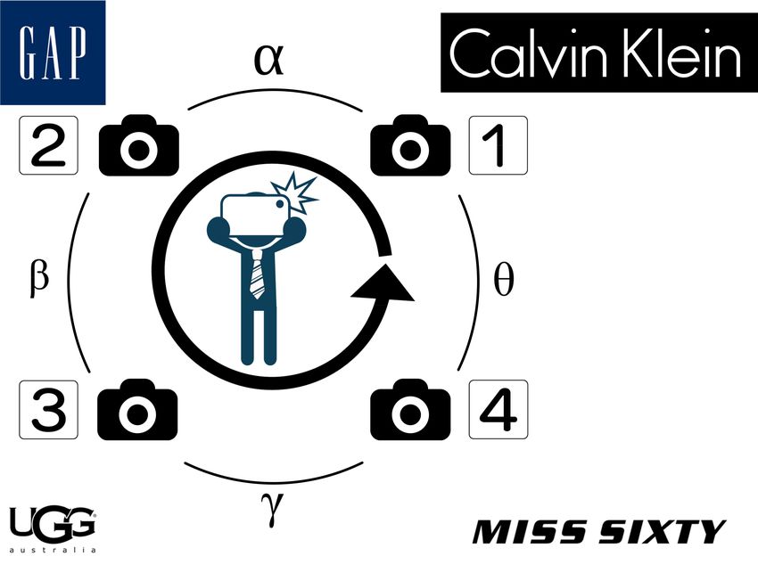
2019 IEEE International Symposium on Dynamic Spectrum Access Networks (DySPAN)

       (a) Indoor Floor-plan Image                                         (b) Circle Shoot                             (c) Location & Heading

                                       Fig. 1: Illustration of an example of the EyeLoc innovation.

on Android smartphones and evaluate its performance in an                       surrounding POIs and localize themselves. After fetching the
office environment and two large shopping malls (7,500m2 and                    floor-plan images, Eyeloc enables the smartphone to imitate
10,000m2 ). The evaluation results show that the 90-percentile                  human self-localization with on-board motion sensors and
error of localization and heading direction can achieve 4m and                  technologies of text detection and recognition. Bootstrap cost
20◦ . The contributions of this paper are as follows.                           and user training are no longer in need.
   • We propose EyeLoc, a smartphone vision enabled plug-                          Fig. 1 provides an example of how EyeLoc works. Alice
      and-play indoor localization in large shopping malls. No                  is in a large shopping mall and she wants to go to H&M.
      site survey or periodical system calibration is required.                 She loses her direction and does not know where she is.
   • We develop a ubiquitous smartphone vision system and                       As Alice opens Eyeloc, the corresponding floor-plan image
      corresponding geometric localization model. To guaran-                    is automatically fetched. Then she holds her smartphone and
      tee localization accuracy and processing efficiency, we                   turns a 360◦ circle. EyeLoc takes a set of view images during
      propose the countermeasures to address several practical                  Alice’s turning. This operation is called circle shoot. From
      challenges.                                                               view images, Eyeloc exploits the motion sensors and tech-
   • We implement EyeLoc on Android smartphones and                             niques of text detection and recognition to extract geometric
      evaluate its performance in an office environment and                     information of several observed POIs (e.g., GAP, UGG, MISS
      two large shopping malls. The evaluation results show                     SIXTY, Calvin Klein). Meanwhile, EyeLoc uses techniques
      that EyeLoc is effective on both localization accuracy                    of text detection and recognition to find the positions of
      and processing efficiency.                                                corresponding POIs on the floor-plan image. Finally, Eyeloc
   The rest of this paper is organized as follows. Section II                   projects Alice’s position and heading direction on floor-plan
shows the overview of EyeLoc. Section III illustrates the                       image as shown in Fig. 1(c).
detailed design of EyeLoc. Section IV and Section V show the                       As Fig. 1 illustrates, EyeLoc depends on techniques of text
details of EyeLoc implementation and evaluation, respectively.                  detection and recognition to extract geometric information of
Section VI introduces the related work. Finally, we conclude                    the observed POIs from a set of view images. Text detection
our work in Section VII.                                                        and recognition from color images have been widely studied
                                                                                in the past decade, especially with deep learning models like
                     II. E YE L OC OVERVIEW
                                                                                convolutional neural networks. A few open-source models
   GPS is a plug-and-play localization system in outdoor                        (e.g., OpenCV [1] , Tesseract [15]) are also available on smart-
spaces and has been widely used by smartphone applications.                     phones. On the other hand, smartphones can utilize the cloud
In large shopping malls, EyeLoc has two goals as GPS does.                      service from companies like Google, Baidu, etc. However,
   • plug-and-play. EyeLoc should not assume any extra boot-                    none of the two approaches can achieve real-time execution
      strap cost (e.g., site survey, system calibration) in large               due to computation overhead on images or extra network
      shopping malls. Moreover, EyeLoc should not require                       delay. This contradiction obliges us to design an efficient
      users to own any prior knowledge and follow complex                       method to accurately extract the geometric information of
      smartphone operations.                                                    the observed POIs, but shorten the processing latency. We
   • efficient and robust. Facing computation intensive image                   have two intuitions for the method design. First, since the
      processing and various measurement errors from motion                     extracted POIs with error geometric information are useless
      sensors and floor-plan images, EyeLoc should be able to                   even harmful for localization, we should not deal with those
      accurately localize a user with short processing time.                    view images of low quality. Second, we observe that the view
   To meet the first goal, EyeLoc is inspired by two obser-                     images are usually redundant for extracting the geometric
vations. First, the indoor floor-plan images of shopping malls                  information of an observed POI. Hopefully, we can only
(e.g., shown in Figure 1(a)) can be easily fetched from indoor                  select a subset of those view images which contains equivalent
map providers through Android and IOS APIs. The other                           geometric information of the observed shops as the whole set
observation is that people usually turn around to observe the                   does for further processing.

       Authorized licensed use limited to: Michigan State University. Downloaded on May 03,2021 at 18:53:02 UTC from IEEE Xplore. Restrictions apply.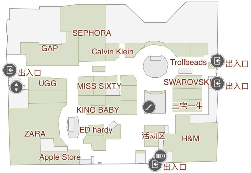
2019 IEEE International Symposium on Dynamic Spectrum Access Networks (DySPAN)

                     Raw Data Collection                                   POI Extraction                                               Position Matching

                                                                                                  Observed
                           Camera          View Images                                                                   POI Grouping
                                                                                                  POI Name                                      Geometric
                                                           View Image       Sparse Image                                                       Localization
      Circle Shoot                                                                                                        POI Tuple 1
                                                             Filtering       Processing
                           Motion          View Image                                             Observed                                                    User Position
                           Sensor           Attribute                                            POI Direction            POI Tuple 2                          & Heading

                                                                                                                              …                   Error
      Coarse GPS          Indoor Map        Floor Plan     Text Detect &      POI Name            Observed                                     Estimation
                                                                                                                          POI Tuple k
      Localization          Provider         Images         Recognize         Matching           POI Position

                                                Fig. 2: Illustration of the system architecture of EyeLoc.

   On the other hand, various measurement errors of the                             geometric information in vision space and positions in floor-
extracted information are invertible and may lead to inaccurate                     plan space. The observed POIs are grouped into tuples. Each
localization. For example, as shown in Fig. 1(c), the text                          POI tuple can be used to calculate the user’s position and
bounding boxes of the four observed shops may be not exactly                        heading direction with geometric constraints. The localization
align to that of the corresponding shop signs appeared in                           error of different tuples are diverse with the same measurement
vision space. To mitigate potential errors and achieve robust                       errors. EyeLoc combines several inferred positions and the
localization, our observation is that the spatial POI distribution                  corresponding errors to vote the final user’s position and
is usually dense in large shopping malls, which means multiple                      heading direction.
POIs are available. Hopefully, we can use the the redundant
information to refine the estimated user’s position.                                                                   III. E YE L OC D ESIGN
   In comparison with human binocular vision system, EyeLoc                            To relieve human from self-localization, EyeLoc achieves
develops a monocular vision system, which is accurate and                           plug-and-play localization in large shopping malls. Due to the
ubiquitous for smartphones. EyeLoc enables user’s position                          huge difference between human vision system and smartphone
matching between vision space and floor-plan space with                             vision system, we first establish the smartphone vision system
constant geometric constraints of 3 observed POIs. The system                       and illustrate the fundamental geometric localization model in
architecture of Eyeloc is shown in Figure 2, including three                        EyeLoc. Then we show the design details of the three function
parts as follows.                                                                   components of EyeLoc as shown in Figure 2.
   Raw Data Collection. The first part is to fetch floor-plan
                                                                                    A. Smartphone Vision System
images from indoor map providers and collect raw information
of view images from circle shoot. According to the coarse                              We intend to define a ubiquitous smartphone vision system
GPS localization, Eyeloc queries indoor map providers to                            to fetch the geometric relationship between the smartphone
obtain floor-plane images. During the circle shoot, Eyeloc                          and an observed POI. Human eyes form a binocular vision
uses camera and motion sensors (e.g., compass, gyroscope,                           system, which enables humans to estimate the distance of
accelerometer) to continuously capture view images and corre-                       an observed POI and the direction of the sightline between
sponding motion attributes (e.g., camera facing direction, angle                    the POI and human eyes. However, nowadays only a few
velocity).                                                                          smartphones (e.g., iPhone X, Huawei P20 Pro) have dual
   POI Extraction. Taking the information of view images and                        or triple cameras and parameters of camera calibration are
floor-plan images as input, the second part extracts geometric                      not explicitly known. Moreover, humans have practiced a lot
information of several observed POIs in both vision space                           since they were children. So the question is can we estimate
and floor-plan space. Because text detection and recognition                        the distance and the direction as geometric descriptors of an
are time-consuming, we need to extract enough geometric                             observed object through the monocular view images of circle
information while keeping the number of processed image as                          shoot?
small as possible. Eyeloc filters out some view images which
are blurred or have error motion attributes. Then EyeLoc
develops a sparse image processing method to extract geo-
metric information of all observed POIs from the rest of view
images and keeps the number of processed image small. After
extracting all POIs on floor-plan image, EyeLoc obtains the
positions of the observed POIs in floor-plan space by matching
their names.
   Position Matching. With the geometric information of the                                (a)                   (b)                     (c)                     (d)
observed POIs, EyeLoc now projects the user’s position and
heading direction to floor-plan space. The redundancy of the                        Fig. 3: An example of the sightline change during circle shoot
observed POIs is explored to mitigate unavoidable errors of                         in physical space.

        Authorized licensed use limited to: Michigan State University. Downloaded on May 03,2021 at 18:53:02 UTC from IEEE Xplore. Restrictions apply.
2019 IEEE International Symposium on Dynamic Spectrum Access Networks (DySPAN)
P Algorithm 1 Geometric Constraints Extraction Algorithm
Input: 3 POIs sorted according to their appearance order; the direc-
tions of the corresponding EyeLoc sightline δ1 , δ2 , δ3 in vision
K1 space.
Output: rotation directions d12 , d23 , d31 , intersection angles θ12 ,
K2
θ23 and θ31 .
d
1: vector of POI1 EyeLoc sightline v1 = (sin δ1 , cos δ1 ).
2: vector of POI2 EyeLoc sightline v2 = (sin δ2 , cos δ2 ).
O1
C1 O2
3: vector of POI3 EyeLoc sightline v3 = (sin δ3 , cos δ3 ).
C2
f F1 4: d12 = v1 × v2 , d23 = v2 × v3 and d31 = v3 × v1 .
θ1 θ2
5: θ12 = (δ2 −δ1 ) mod 360◦ ; θ23 = (δ3 −δ2 ) mod 360◦ ; θ31 =
f
F2
r
r
H
(δ1 − δ3 ) mod 360◦
Fig. 4: Distance measurement with circle shoot.
12◦ and 2.11, d will be 5.48m. We change one parameter (e.g., θ1 ,
Angle θ1 (°) 4
23.9 23.95 24 24.05 24.1 3
θ2 , k) to calculate the distance error when other parameters are fixed.
4
Angle θ1 2 The results are shown in Fig. 5. Surprisingly, given the distance as
Distance Error (m)
3
Distance Error (m)
2 Angle θ2
1
1 0
5.48m, the distance error is huge when θ1 , θ2 and k have a small
0
-1
-1 bias. The distance error is getting to 1.97m, when θ1 decreases from
-2 -2
24◦ to 23.9◦ . Similarly, when θ2 increases from 12◦ to 12.1◦ , the
-3 -3
-4
11.9 11.95 12 12.05 12.1
-4 distance error increases from 0m to 2.68m. 0.1◦ error is common
2.1 2.12 2.14 2.16 2.18
Angle θ2 (°) Ratio of Pixel Offset for the facing direction measurement with motion sensors. The same
(a) Influence of θ1 and θ2 (b) Influence of k
trend happens on k. When k increases from 2.11 to 2.16, the distance
error increases from 0m to 3.77m. Due to the limitation of image
resolution, given F1 C1 is as large as 1000 pixels, 0.05 error of k
Fig. 5: Illustration of distance error in terms of the error of θ2 means about no more than 50 pixels error of F2 C2 which is hard to
and k. (a) and (b) show the distance error under different θ2 achieve due to the relatively large estimation error of text bounding
and k when other parameters are fixed. box. When θ1 increases or θ2 and k decreases a little, the situation
is getting even worse. Hence, due to the limitation of motion sensor
precision and image resolution, the potential huge error makes the
To enable distance estimation with monocular vision, one distance estimation unavailable in practice. Overall, in smartphone
vision system, for a POI, we only use the direction of its EyeLoc
way is to exploit the camera motion of circle shoot to imitate sightline as the geometric descriptor for later localization.
a binocular vision system. As shown in Fig. 4, the distance
between the POI P and the user H is indicated as d. The B. Geometric Localization Model
distance between H and the optical center of smartphone After we obtain the direction of the sightlines of several POIs,
camera lens O1 is r. C1 is the center of image plane while the next question is how to construct constant geometric constraints,
then figure out the user’s position and heading direction on floor-plan
F is the position of P on the image. H1 , C1 and O1 are image.
approximately kept on the same line all the time during 1) Constant Geometric Constraints: Taking Fig. 6 as an
circle shoot. The focal length of the smartphone camera example, H is the user’s position. Fig. 6(a) represents the vision
lens f is unknown for most smartphones. θ1 indicates the space. The user observes 3 POIs (e.g., POI1 Miss Sixty, POI2 UGG
intersection angle between line HO1 and the sightline HP . and POI3 GAP) in their appearance oder. Nv indicates the north
direction in vision space. Fig. 6(b) represents the floor-plan space.
Since 4F1 O1 C1 is similar to 4P O1 K1 , we have the follow Circle 1, 2 and 3 in Fig. 6(b) represent the corresponding center of
equation: text bounding boxes of the 3 observed POIs. Given the coordinate
F1 C1 f system X-Y of the floor-plan image, (x1 , y1 ), (x2 , y2 ) and (x3 , y3 )
= (1)
d sin θ1 d cos θ1 − r are the corresponding coordinate of 1, 2 and 3. Nf is the north
direction in floor-plan space which aligns with Y axis. In vision
where F1 C1 indicates the pixel offset between F1 and C1. space, the directions of EyeLoc sightline δ1 , δ2 and δ3 can be
Combining the same equation under another angle θ2 (θ1 6= estimated. However, since Nv and Nf may be not aligned with each
θ2 ), we can derive d as follow: other, we cannot directly determine the coordinate of H with these
sin θ1 − k sin θ2 directions in floor-plan space.
d=r (2) Two constant geometric constraints between the vision space and
cos θ2 sin θ1 − k cos θ1 sin θ2
the floor-plan space are important for EyeLoc. The first one is that
where k equals to the ratio between F1 C1 and F2 C2 . If θ1 , θ2 , k the rotation direction of the circle shoot is constant. The 3 POIs
and r are known, the distance d can be calculated. As the direction will appear in the same order along the rotation direction in vision
of HP , HO1 and HO2 can be obtained by motion sensors, θ1 and space and floor-plan space (e.g., POI1 →POI2 →POI3 in Fig. 6(a)
θ2 can be calculated. For an observed POI, we recognize the center and 1 → 2 → 3 Fig. 6(b)). We use d12 , d23 and d31 to indicate
of its text bounding box as F1 and F2 on a view image so that F1 C1 , rotation directions between each pair of adjacent POIs. The second
F2 C2 and k can be calculated. r can be roughly estimated according constant geometric constraint is, 6 POI1 HPOI2 , 6 POI2 HPOI3 and
to human arm length. In this way, EyeLoc can estimate the distance 6 POI3 HPOI1 in Fig. 6(a) are equal to 6 1H2, 6 2H3 and 6 3H1 in
of a POI in large shopping malls without any prior knowledge of Fig. 6(b) respectively. To simplify our notations, the 3 intersection
camera parameters. angles are indicated as θ12 , θ23 and θ31 in both spaces. The rotation
Since the errors of θ and k estimation are inevitable, we conduct directions and the intersection angles between any two POIs serve as
error analysis. We assume r is 0.5m. Given θ1 , θ2 and k are 24◦ , two constant geometric constraints between the vision space and the
Authorized licensed use limited to: Michigan State University. Downloaded on May 03,2021 at 18:53:02 UTC from IEEE Xplore. Restrictions apply.
2019 IEEE International Symposium on Dynamic Spectrum Access Networks (DySPAN)
Y
Nv POI1 Miss Sixty
H
(x3,y3)
!1 3
θ12
θ31
θ23
H
2 θ12 1
θ31 O’12
(x2,y2) (x1,y1)
H θ12
2
d12
(x2,y2)
!3 θ23 !2
M
R 180º-θ12 1
POI3 GAP POI2 UGG (x1,y1)
R
X O12
Fig. 6: Illustration of the model used to localize a user’s position on floor-plan image with 3 observed POIs. (a) and (b) exhibit
a constant geometric constraint in both vision space and floor-plan space. (c) shows the model to calculate the user’s location
with the extracted geometric information.
Algorithm 2 Arc Calculation Algorithm following equation:
Input: 2 POIs, POI1 and POI2 , sorted according to their appearance x1 − x2 yo − yM
order; the rotation direction d12 ; the angle θ12 between the =− =k (3)
y1 − y2 xo − xM
directions of the corresponding EyeLoc sightlines in vision space;
the corresponding coordinates (x1 , y1 ) and (x2 , y2 ) in floor-plan ~ Moreover, the central angle
where k is the slope of the chord 12.
space. 6 1O12 2 is twice the corresponding inscribed angle which equals to
Output: The coordinate of circle center (xo , yo ); the length of circle 180◦ − θ12 and 6 1O12 M is half the central angle 6 1O12 2. Hence,
radius R. 6 1O12 M = 180◦ − θ12 and R = d12
. As for the length of
pixel distance and slope of the chord 12
1: p ~ as d12 = 2 sin θ12
−x2 O12 M , we have the follow equation:
(x1 − x2 )2 + (y1 − y2 )2 and k = xy11 −y 2
.
2: if θ12 equals to 180◦ then p l12
(xo − xM )2 + (yo − yM )2 = − (4)
3: H is on the segment between POI1 and POI2 . (xo , yo ) and R 2 tan θ12
are set as NULL.
4: else if θ12 > 180◦ then
Combining Equ. 3 and Equ. 4, we can obtain (xo , yo ) as follows:
5: θ12 = 360◦ − θ12 . l12
6: else if θ12 equals to 90◦ . then xo = xM ± √ (5)
2 y1 +y2 2 tan θ12 1 + k2
7: (xo , yo ) = ( x1 +x
2
, 2 );R = d12 /2
kl12
8: else yo = yM ∓ √ (6)
9: R = 2 sin d12
; two possible coordinates (xo1 , yo1 ) and 2 tan θ12 1 + k2
θ12
(xo2 , yo2 ) of circle center are calculated by Equ. 6 and Equ. 6. Besides O12 , we obtain another false center of circle O12 0
which is
10: set (xo , yo ) as (xo1 , yo1 ) symmetric with O12 by taking 12 ~ as mirror. To filter out the outlier
11: calculate the rotation direction do12 = vector(xo − x1 , yo − 0
O12 , we further exploit the information of the rotation direction d12
y1 ) × vector(xo − x2 , yo − y2 ) and acute/obtuse angle θ12 . If θ12 is acute angle, O12 is on the same
12: if d12 · do12 > 0 ⊕ θ12 < 90◦ . then side with H regarding segment 12. ~ Otherwise, O12 is on the opposite
13: set (xo , yo ) as (xo2 , yo2 ). side with H. In this way, we can identify the unique coordinate of
14: end if O12 . Alg. 2 summarizes the detailed calculation of O12 and R. Now,
15: end if
we know H is on an arc determined by O12 and R. Similarly, we can
calculate another arc where H is on with POI2 , POI3 and θ23 . We
further calculate the intersections of these two arcs. One intersection
is POI2 , the other is the position of H.
floor-plan space. Alg. 1 exhibits the details to determine the d12 , d23 , In the localization model, we should notice an unexpected situation
d31 , θ12 , θ23 and θ31 given 3 POIs and their corresponding directions which may incur localization bias. The situation is that when H,
of EyeLoc sightlines. POI1 , POI2 and POI3 are on the same circle, we cannot localize
2) Localization Model: Given three POI coordinates ((x1 , y1 ), H through the geometric constraints of the 3 POIs. This situation
(x2 , y2 ), (x3 , y3 )), rotation directions (d12 , d23 , d31 ) and intersection rarely happens in practice as shown in Section V. Moreover, it is
angles (θ12 , θ23 , θ31 ), we derive a method to calculate the coordinate possible that we can observe more than 3 POIs at large shopping
(xH , yH ) of the user’s position H in the floor-plan space. As shown malls. If the situation has happened, EyeLoc will popup a message to
in Fig. 6(c), we have the coordinates of two POIs (e.g., 1, 2), the remind the user that he/she needs to walk several steps and relocalize
rotation direction d12 and the intersection angle θ12 . If θ12 is 180◦ , H himself/herself.
is on the segment between 1 and 2. Otherwise, the possible position When the coordinate of H is known, we can calculate the
of H is on an arc which takes the segment 12 ~ as the chord and θ12 as directions of HPOI1 , HPOI2 and HPOI3 in floor-plan space. Then,
the inscribedp angle. The pixel distance between 1 and 2 is l12 which with δ1 , δ2 and δ3 , we can calculate the angle offset ∆N between the
equals to (x1 − x2 )2 + (y1 − y2 )2 . M is the middle point of the vision north Nv and floor-plan north Nf . Given any user’s heading
chord 12 ~ and its coordinate (xM , yM ) equals to ( x1 +x2 , y1 +y2 ). direction (e.g., camera facing direction) in vision space, we can infer
2 2
O12 is the center of the circle and R is the length of its radius. We his/her heading direction in floor-plan space. Overall, EyeLoc can
use (xo , yo ) to indicate the coordinate of O12 . If θ12 is 90◦ , O12 calculate a user’s position and heading direction by observing no
and M will share the same coordinate. Otherwise, since 1 and 2 are less than 3 POIs. In the next 3 subsections, we will address several
on the circle and the chord 12 ~ is perpendicular to M O12 , we have challenges in practice.
Authorized licensed use limited to: Michigan State University. Downloaded on May 03,2021 at 18:53:02 UTC from IEEE Xplore. Restrictions apply.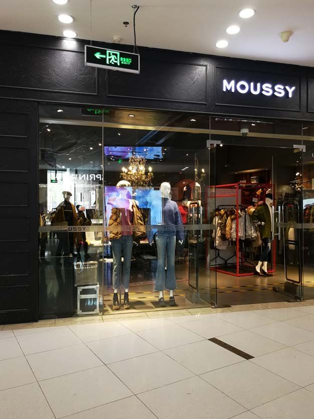
2019 IEEE International Symposium on Dynamic Spectrum Access Networks (DySPAN)
Smartphone Z 60
1
Accelerometer+Compass
50
Probability of Text Detection
Gravity
Groscope
Y
Angle Velocity (°/s)
40 0.8
X
30
0.6
CDF
20
Ea 10 0.4
No rth
rth 0
0.2 CDF
Z’
-10
Text Detection
Earth 0 5 10 15 20 25 30 35 40
! East Picture ID
0
0 50 100 150 200 250 300 350 400
Image Laplacian Variance
Fig. 8: The angle velocity measured
Fig. 7: Illustration of the camera by different combination of motion Fig. 9: The influence of image blur on
facing direction δ measurement. sensors. the accuracy of text detection.
C. Raw Data Collection available POIs and corresponding geometric information from a set
of view images for later position matching.
During circle shoot, EyeLoc periodically takes view images with
camera and records the readings of motion sensors to infer the camera 1) View Image Outlier Filtering: If a view image is blurred,
facing direction of each view image in vision space. Moreover, we cannot detect any text at all. We treat the blurred view images
EyeLoc fetches the floor-plan images from indoor map provider. as outlier that should be filtered out. EyeLoc adopts Laplacian-based
1) View Image: We have two system parameters for view image operator, which is a widely used function for focus measure, to define
shooting. One is the resolution of view image, indicated as Ir . The the degree of image blur. We randomly selected 1692 view images
higher the Ir is, the text of more POIs can be accurately detected from the whole data set shot in two large shopping malls (Section V).
and recognized. However, the processing time also increases when We guarantee there are at least one POI sign in each of these view
Ir becomes high. Hence, EyeLoc fixes Ir as 1536p during circle images. In Fig. 9, the black curve shows the Laplacian variance
shoot but adaptively chooses a small resolution Ip for later POI values of these images are distributed from 0 to 400. The larger
text detection and recognition. The other parameter is the shooting the variance is, the less the image blur is, as shown the comparison
frequency fs . The interval between two adjacent view images is 1/fs . between the example view images with variance in the range [0,20]
The high fs ensures all surrounding POIs can be recorded when the and [300,320]. In a view image, if the length of any recognized text
rotation speed of a user is fast. Too many redundant view images string is more than 2, it is text detectable. We further select 15 view
also have negative influence on processing time. EyeLoc selects a images from each level of image blur to evaluate the the probability of
relatively high fs to guarantee the reliability and further improves text detection under different level of image blur. The red curve shows
the processing efficiency through view image filtering and selection. that the probability of text detection is higher than 80% when the
Laplacian variance is larger than 80. Hopefully, we should filter out
2) Motions Sensor Readings: In Section III-B, we have men-
those view images whose Laplacian variance is less than 80 because
tioned that the EyeLoc direction of each view image is measured
it is hard to detect any text clues from it. Thus, we define a threshold
through the estimation of camera facing direction. According to the
∆Lap (e.g., approximate 80) to determine whether a view image is
common gesture of circle shoot shown in Fig. 3(a), as Fig. 7 shown,
blurred or not.
δ is the angle between earth north Ne (i.e., Nv in EyeLoc vision
system) and the projected direction Z 0 of smartphone Z axis. We Moreover, the smartphone vibration around Y axis and Z axis
use the motion sensors (e.g., accelerometer, gyroscope and compass) can influence the position of a POI on view images. As a result, the
to capture the camera facing direction. EyeLoc continuously samples estimation error of EyeLoc sightline may increase. The gyroscope
the readings of the motion sensors. Basically, the acceleration along outputs the angle velocity p around 3 axes as ωx , ωy and ωz , then
3 smartphone axes (e.g., X, Y and Z) can determine the direction the angle velocity is ω = ωx2 + ωy2 + ωz2 . On the other hand, we
of gravity. Compass can further determine the direction of Ne in can also calculate the angle velocity ω 0 given the Z 0 direction of
smartphone coordinate system. As a result, the direction of Z can be two adjacent view images and the corresponding time interval. We
calculated in earth coordinate system. Then, the direction of Z 0 and δ conduct a circle shoot by setting fs as 2Hz. During circle shoot, we
are calculated correspondingly. Furthermore, EyeLoc adopts several manually vibrate the smartphone as a common user does when the
methods [23] [11] to calibrate the camera facing direction of each picture ID is from 15 to 18 and from 26 to 30. As shown in Fig. 8,
view image by removing potential magnetic interference and bursty the angle velocity difference between ω and ω 0 is close to zero as
noise. usual. However, the smartphone vibration will obviously increase the
3) Floor-plan Image: . By utilizing the API provided by indoor difference. This observation indicates different motion sensors have
map provider, given the coarse GPS readings in a shopping mall, different sensitivity for the vibration. Hence, EyeLoc sets a threshold
EyeLoc can fetch the floor-plan images of all floors in the shopping ∆ω and filters those view images when the angle velocity difference
mall. Each floor-plan image contains the skeleton and name of all is larger than ∆ω .
POIs on that floor. 2) Text Filtering and Matching: In large shopping malls, text
Overall, the raw data collection module outputs a series of view may appear at anywhere. It is possible to detect multiple text strings
images, corresponding EyeLoc sightline directions and floor-plan from a view image, especially the name of a POI may appear at
images. However, in raw data, the redundancy and measurement multiple places. EyeLoc filters out the irrelevant and duplicate text
error incur computation inefficiency and localization error. Next, we bounding boxes through following steps. First, given the minimum
introduce the methods to improve the efficiency and robustness. and maximum length of POI names extracted from floor-plan images,
EyeLoc filters out the illegal text strings. Second, we group the rest
of text strings. Two text strings belong to the same group when
D. POI Extraction the difference between them is smaller than a threshold ∆t . The
EyeLoc fetches the names and positions of all POIs in a shopping difference between two text string is defined as the ratio between
mall from floor-plan images. The problem is to efficiently extract all their Levenshtein Distanceand the maximum string length. Given the
Authorized licensed use limited to: Michigan State University. Downloaded on May 03,2021 at 18:53:02 UTC from IEEE Xplore. Restrictions apply.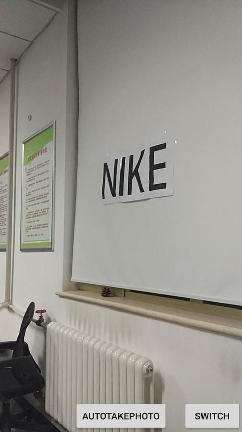
2019 IEEE International Symposium on Dynamic Spectrum Access Networks (DySPAN)

                                                                                                          Error User Position                           Error User Position
                                                                                                                   Error POI                                                    POI3
                                                                                                   POI2                         POI3            POI2

                                                                                                                   H                                              de

                                                                                          Y axis

                                                                                                                                       Y axis
                                                                                                                       de                              θ12       H            θ’12

                                                                                                                      Re
                                                                                                     POI1                                              POI1

                                                                                                               X axis                                         X axis

          I1                      I2                                                                      (a) POI Error                            (b) Direction Error

Fig. 10: Feature point matching in two different view                             Fig. 11: The localization sensitivity regarding to (a) POI error
images of the same POI.                                                           and (b) direction error.

list of POI names extracted from floor-plan images, EyeLoc further               E. Position Matching
removes those invalid groups whose text strings are not on the list
                                                                                     According to the localization model in Section III-B, we can
(i.e., the similarity is smaller than ∆t in comparison with any POI
                                                                                 localize a user’s position with three observed POIs, called localization
name). Finally, in each valid group, EyeLoc combines the coordinates
                                                                                 tuple. Fig. 11 shows the measured POI coordinates of a localization
of all text bounding boxes to calculate the average value as the unique
                                                                                 tuple (e.g., POI1 , POI2 , POI3 ) and the calculated user’s position H.
text bounding box position of the observed POI on the view image.
                                                                                 The corresponding measured intersection angle θ12 , θ23 and θ31 are
In this way, EyeLoc identifies the available POIs and corresponding
                                                                                 120◦ . The POI text bounding boxes in floor-plan image may not
position of text bounding boxes on a view image.
    3) Sparse Image Processing: After filtering the outliers of view             exactly align with that in physical space. Due to the POI coordinate
images, for all observed POI, we need to exactly find the view images            errors, we assume the true POI positions may appear on a circle
(e.g, Fig. 3(c)) where the corresponding text bounding boxes appear              around it and the radius is Re . As shown in Fig. 11(a), given the POI1
in the middle of. The intuitive approach is to process all view images,          uncertainty Re as 3 pixels, we fix other measured results, the possible
but incurs heavy networking and computation burden as the sampling               true positions shown as the green marks are calculated. Moreover, due
frequency fs is set high. Even worse, the desired view image may                 to the possible errors from motion sensor and image processing, θ12
not be captured or blurred. Instead of processing every view image               may inaccurately measured in comparison with the true intersection
                                                                                         0
to extract the geometric information of all potential POIs, EyeLoc               angle θ12  as shown in Fig. 11(b). The same situation may happen for
develops a sparse image processing approach to achieve the same                  θ23 and θ31 . We assume the error of θ12 , θ23 and θ31 is in the range
goal. The key idea is after the position of a text bounding box is               of [−∆θ , ∆θ ]. For θ12 , Fig. 11(b) shows the possible true positions
known from a view image (e.g., Fig. 3(b)), we can enable EyeLoc                  shown as the green marks when ∆θ is 10 ◦ . Regarding to the errors
sightline estimation of a POI with one more view image which                     of P OI1 and θ12 , the maximum localization errors are indicated as
contains the same POI (e.g., Fig. 3(d)) by feature point matching.               de . The ratio between de and Re or ∆θ is further defined as the error
As shown in Fig. 10, given two view images I1 and I2 , the text                  sensitivity of a POI or an intersection angle. Given a localization tuple
bounding box of I1 is extracted and it is d1 pixel from the middle               u, we define its localization error sensitivity les(u) as the sum of
line. Then, in I2 , we use ORB algorithm to extract the same feature             the error sensitivity of all three POIs and three intersection angles.
points which falls into the text bounding box of I1 . Given a feature                When k (k ≥ 3) POIs are extracted, we have total m = k(k −
point, its coordinates on I1 and I2 arep    (x1 , y1 ) and (x2 , y2 ). The       1)(k − 2)/6 localization tuples indicated as {u1 , u2 , ..., um }. For the
pixel distance of the feature point is       (x1 − x2 )2 + (y1 − y2 )2 .         ith tuple ui , its localization result and error sensitivity are indicated
The average pixel distance of all feature points is indicated as lf .            as hi and les(ui ). The larger the les(ui ) is, the more accurate the
Due to the approximate constant ratio between pixel distance and                 hi is. Hence, EyeLoc sets the weight wi of localization result hi as
central angle, given their direction as δ1 and δ2 , we can calculate the         1/les(ui ). Then, the final match location h are calculated as follows:
direction δ of the POI EyeLoc sightline as following:                                                              Pm
                                                                                                                          wi hi
                                       d1                                                                     h = Pi=1  m                               (8)
                         δ = δ1 +         (δ2 − δ1 )                      (7)                                           i=1 wi
                                       lf
When we recognize the text bounding box of a POI from a view                     With h and k extracted POIs, EyeLoc can further calculate user’s
image, we use its adjacent images which probably contain the same                heading direction according to the method in Section III-B. Overall,
POI to calculate the direction of POI EyeLoc sightline with Equ. 7.              EyeLoc outputs the user’s location and real-time heading directions
   To extract the geometric information of all observed POIs, the                in floor-plan space.
problem becomes to quickly find a view image of each observed POI
from all view images. Given n view images {I1 , I2 , ..., In }, we set a                                            IV. I MPLEMENTATION
step length ∆s and view images {I∆s , I2∆s , ..., Ik∆s } (k = b ∆ns c)
are selected for processing. Hopefully, if the minimum number of                    We implement EyeLoc as a mobile application in Android 7.0.
view images of a POI is larger than ∆s , EyeLoc cannot miss the view             Fig. 12 demonstrates the user interface (UI) of EyeLoc application
image of any observed POI. However, due to the possible fail of text             when we conduct experiments in the office environment (Section V).
recognition, we may miss some POIs so that no more than three POIs               As shown in Fig. 12(a), after a user opens EyeLoc application, the
are extracted. In this case, EyeLoc will exponentially reduce ∆s and             surrounding view appears on the smartphone screen. Then, the user
reprocess the new view images until at least 3 POIs are extracted or all         clicks “AUTOTAKEPHOTO” button to trigger circle shoot. After the
view images are processed. Overall, we can fetch enough available                user finishes circle shoot, he/she clicks “STOPTAKEPHOT” button.
POIs and corresponding directions of EyeLoc sightline as soon as                 Later on, EyeLoc exhibits the user’s position (e.g., black spot) and
possible for later location matching. Next, we remove the potential              heading direction (e.g., orange arrow) on floor-plan image as shown in
estimation errors to achieve accurate location matching.                         Fig. 12(b). We discuss several system details and settings as follows.

        Authorized licensed use limited to: Michigan State University. Downloaded on May 03,2021 at 18:53:02 UTC from IEEE Xplore. Restrictions apply.
2019 IEEE International Symposium on Dynamic Spectrum Access Networks (DySPAN)
set Ip as 1080p. For outlier view image filtering, according to the
observation of Fig. 9 and 8, we set ∆Lap and ∆ω as 80 and 10◦ /s.
B. Circle Shoot Operation
We set fs as 2Hz, namely EyeLoc shoots 2 view images per
second. Moreover, we set ∆s as 3. Considering the observed 20%
blurred view images (Fig. 9) and 37% text recognition failure of
( a) (b)
1080p view image (Fig. 13(b)) in practice, according to our empirical
experience, it is better to obtain at least 6 view images of a POI (e.g.,
Fig. 12: The EyeLoc UI. 3s) to ensure the reliability and efficiency of POI extraction. That
80
80
means if there are 5 POIs around a user, the circle shoot will take
Accuracy (%)
60
Accuracy (%)
60
40 15s at least.
40
20
20
0
0 C. Floor-plan Images
Time (s)
2
60
Time (s)
40 1 EyeLoc generates high resolution indoor floor-plan images from
20 0
0
0 0 0 0 0 0 0 0 0 6
18 27 36 48 60 72 96 108 120 153 Gaode Maps. Since the font of POI texts on floor-plan images is
Tesseract OpenCV Baidu Cloud Image Resolution
regular print format, the text recognition accuracy is close to 100%.
(a) Different text recognition ap- (b) Different image resolution The resolution of floor-plan image is set to 2560×1440. For error
proaches choices sensitivity estimation, we empirically set ∆θ and Re as 10◦ and 20
pixels. The threshold of text string similarity ∆t is set as 50%.
Fig. 13: The performance under different text recognition
approaches and different image resolution choices. V. E VALUATION
We evaluate EyeLoc with different smartphones (e.g., MI 5 and
Huawei Mate 7) in office environment and two large shopping malls.
The office environment is a 7m×9m office room as shown in Fig. 12.
A. Scene Text Detection and Recognition We print 6 shop signs such as NIKE on A4 size paper, then hang
Scene text detection and recognition techniques serve as a funda- them on the wall or curtain in clockwise order. The area of each floor
mental role in EyeLoc. We compare several existing techniques which in two large shopping malls are 7,500 m2 and 10,000 m2 respectively.
can work on Android smartphone in terms of recognition accuracy We invited two volunteers (Male, 20-30 years old) to complete all
and processing time. Here, we adopt the same method in Section III-D the experiments both in daytime and night. User 1 uses MI 5, User 2
to judge the similarity between two text string. ∆t is set as 50%. We uses Huawei Mate 7. The two users exhibit different habits as User
randomly select 100 images which are shot by smartphone in two 1 turns faster than User 2.
large shopping malls. Some of them are shot at daytime and the
others are shot at night. Each image contains one shop sign which is 1 1
manually labeled as the ground truth. 0.8 0.8
1) Local processing v.s. Cloud processing: According to the 0.6 0.6
CDF
CDF
different processing platform, there are two kinds of approaches
0.4 0.4
for text detection and recognition. One is to locally process image
0.2 0.2
on smartphone. The other is on cloud. The approaches of local Office Environment Office Environment
Large Shopping Malls Large Shopping Malls
processing include OpenCV [1] and Tesseract [15]. We choose Baidu 0
0 1 2 3 4 5
0
0 5 10 15 20 25 30
Cloud as a typical cloud processing approach. We use LTE network, Localization Error (m) Heading Direction Error (°)
which is available in most shopping malls nowadays, to connect the (a) The CDF of localization error in (b) The CDF of facing direction error
smartphone with cloud server. Given the data set of 100 images, the different environments in different environments.
recognition accuracy and processing time are shown in Fig. 13(a).
We can see that the text recognition accuracy of Baidu Cloud is 66% Fig. 14: The reliability of EyeLoc.
which is much higher than 12% of Tesseract and 2% of OpenCV. The
text recognition accuracy of Tesseract and OpenCV is surprisingly
low since the text classifiers and extreme region extraction are hard
4.5 4.5
to adapt the complex lighting condition and text format of the POI 4
3 POIs
4
signs. The average processing time of Baidu Cloud is 2s which is a 3.5
4 POIs
3.5
Localization Error (m)
Localization Error (m)
5 POIs
little higher than that of OpenCV, but much smaller than Tesseract. 3 3
Due to the superior recognition accuracy and low processing time, 2.5 2.5
2 2
we choose cloud processing instead of local processing. 1.5 1.5
2) The influence of image resolution: We further explore the 1 1
performance of Baidu Cloud by using different image resolution. 0.5 0.5
0 0
We vary the resolution of 100 images from 180p to 1538p. The Office Mall MI 5 Huawei Mate 7
performance is shown in Fig. 13(b). We can see that both text
(a) The influence of the number of (b) The localization error measured
recognition accuracy and processing time increase with the increasing
observed POIs by different smartphones
of image resolution. When the image resolution is 720p, the text
recognition accuracy and average processing time are 54% and 0.74s.
In comparison, the text recognition accuracy and average processing Fig. 15: Different influencing factors.
time increase to 72% and 1.89s when the image resolution increases
to 1536p. EyeLoc choose Ip to keep the text recognition accuracy is In office environment, we uniformly split the office to 18 areas.
higher than 60%. Meanwhile, EyeLoc minimizes the expected time Users stand at the center of each area. The ground truth is obtained
for successfully recognizing a POI which is the ratio between the through laser rangefinder. In two large shopping malls, we mainly
average processing time and the recognition accuracy. Hence, we select the positions near entrance, elevator and bathroom where users
Authorized licensed use limited to: Michigan State University. Downloaded on May 03,2021 at 18:53:02 UTC from IEEE Xplore. Restrictions apply.
2019 IEEE International Symposium on Dynamic Spectrum Access Networks (DySPAN)

                                                                                 localization error distribution of the 18 experiment positions given the
                                                                                 positions of 6 POIs. The darker the color is, the higher the localization
                                                                                 error is. We can see the localization error is getting higher when the
                                                                                 distance between user’s position and POIs is large. Moreover, the top
                                                                                 left area is higher than its surrounding area, that is because it is close
                                                                                 to the circle formed by several POIs. According to Section III-B,
                                                                                 when the user’s position and POIs tends to be on the same circle, the
                                                             (m)                 accurate localization will be hard to achieve. Moreover, we give two
                                                                                 experiment positions in shopping mall 1 (Fig. 17(a)) and shopping
      Fig. 16: The distribution of the localization error                        mall 2 (Fig. 17(b)). The white areas are roads and yellow blocks are
                                                                                 shops. The green points are the results of EyeLoc localization. The
      in office environment.                                                     red points are the ground truths. The localization error of the position
                                                                                 in shopping mall 1 is 1.56m, but that of the other one is 3.64m.
                                                                                 From the POI distribution on the floor-plan images, we can see the
                                                                                 large error in Fig. 17(b) is because the true position, GLORIA, AFU
                                                                                 and MOFAN tend to on the same circle. In contrast, the position in
                                                                                 Fig. 17 has more POIs which are close to it and uniformly distributed.
                                                                                 Hence, the results suggest that the localization error is indeed related
                                                                                 to the distribution of surrounding POIs, especially when the user’s
                                                                                 position and observed POIs are on the same circle. However, the
                                                                                 situation only happens twice among total 29 positions. If the situation
                                                                                 happens, we will ask the user to walk a short distance and relocalize
                                                                                 himself/herself again.
                                                                                    3) The influence of smartphone hardware: We further evalu-
 Fig. 17: Two experiment positions in two shopping malls.                        ate the localization error by using different smartphones at the same
                                                                                 positions in large shopping malls. The results are shown in Fig. 15(b).
                                                                                 We can see the average localization error is 2.66m for MI 5 and
have high localization demands. We evaluate 11 positions. For each               2.51m for Huawei Mate 7. Since User 2 turns slower than User 1,
position, we also use laser rangefinder to measure its ground truth.             the more redundant view images make the localization error variance
The minimum and maximum distances between the user and a POI                     of Huawei smartphone is smaller than MI 5. Overall, EyeLoc works
are 2.26m and 29.2m.                                                             well on both smartphones and does not depends on any smartphone
                                                                                 specific hardwares and parameters.
A. The Accuracy of Localization and Heading Direction Es-
timation                                                                         B. Processing Efficiency
   First of all, we discuss the reliability of EyeLoc. As shown in                  The other important performance metric is the processing time,
Fig. 14(a) and Fig. 14(b), in the two large shopping malls, the                  which is from the end of circle shoot to the user’s position is
median errors of localization and heading direction are 2.6m and                 shown on the screen. Since the view image processing dominates
10.5◦ . Moreover, the 90-percentile errors of localization and facing            the overall processing time, EyeLoc have designed two approaches,
direction increase to 4m and 20◦ . In the office environment, the 90-            namely outlier image filtering and sparse image processing. We
percentile errors of localization and facing direction are 1.1m and 8◦
which are much better than that in large shopping malls. There are
two reasons. First, in office environment, we can precisely measure                                                        1

the POI coordinates on the floor-plan images. However, the POI                                                            0.8
coordinates suffer larger error due to the position mismatch between
                                                                                                                          0.6
the text bounding boxes and the observed POI signs on the floor-
                                                                                                    CDF

plan images obtained from indoor map providers. Moreover, in office                                                       0.4
environment, we have only one POI in a view image in most cases.                                                                                                         All
                                                                                                                          0.2                                          Filter
However, in large shopping malls, it is possible that several signs                                                                                            Sparse+Filter
of the same POI may appear in a view image. It will incur error                                                            0
                                                                                                                                0    10     20       30   40      50       60   70
about the sightline estimation. EyeLoc fully considers these errors                                                                           Processing Time (s)

and designs countermeasures in both POI extraction and position
matching. Given the area as large as 7,500m2 and 10,000m2 , 4m and               Fig. 18: The processing efficiency with outlier filtering and
20◦ is still relatively accurate for the most location based services.           sparse processing.
   1) The influence of the number of observed POIs: In
position matching, EyeLoc utilizes the POI redundancy to mitigate                                                         70
                                                                                                                                              All
the measurement errors of POI coordinates and EyeLoc sightline.                                                           60                Filter
Fig. 15(a) shows the relationship between the number of observed
                                                                                                    Processing Time (s)

                                                                                                                          50        Sparse+Filter
POIs and the localization error. We can see the average localization
                                                                                                                          40
error decreases as the number of observed POIs increases. Specif-
ically, the localization error decreases by 33.7%/34.9% when the                                                          30

number of observed POIs increases from 3 to 4/5 in large shopping                                                         20

malls respectively. This indicates the error mitigation approaches are                                                    10
effective for improving the localization accuracy. Moreover, 5 or                                                          0
                                                                                                                                               MI5             Huawei
more POIs cannot provides more useful information for improving
the localization accuracy rather than 4 POIs.                                    Fig. 19: The comparison of processing time on different
   2) The influence of POI distribution: We evaluate the influ-
ence of POI distribution on the localization error. Fig. 16 shows the            smartphones.

        Authorized licensed use limited to: Michigan State University. Downloaded on May 03,2021 at 18:53:02 UTC from IEEE Xplore. Restrictions apply.
2019 IEEE International Symposium on Dynamic Spectrum Access Networks (DySPAN)

further evaluate the processing time of three methods: “All” indicates           automatically projects the user’s position and heading direction on the
we process all view images; “Filter” indicates we only process the               floor-plan image. We implement EyeLoc as an Android application
view images after filtering the outliers. “Filter+Sparse” indicates we           and evaluate its performance in various environments. The evaluation
combine outlier filtering and sparse processing approaches. As shown             results show that the 90-percentile accuracy of localization and
in Fig. 18, we can see Filter+Sparse outperforms the other two                   heading direction is 4m and 20◦ .
methods and its median processing time is 18.2s which is 55.5%
shorter than All. Moreover, the median processing time of Filter is                                       ACKNOWLEDGEMENT
27.3s which is 36.2% shorter than All. That verifies both outlier                  This study is supported in part by the NSFC program under Grant
filtering and sparse processing are effective to improve the processing          61772446 and 61872081.
efficiency. In the worst case, the processing time of Sparse+Filter is
37.4s. That means the user can obtain the localization result in no                                             R EFERENCES
more than half minute after circle shoot. Fig. 19 further shows the               [1] G. Bradski and A. Kaehler. Learning OpenCV: Computer vision with
processing time on different smartphones.                                              the OpenCV library. ” O’Reilly Media, Inc.”, 2008.
                                                                                  [2] Y.-C. Cheng, Y. Chawathe, A. LaMarca, and J. Krumm. Accuracy
                        VI. R ELATED W ORK                                             characterization for metropolitan-scale wi-fi localization. In Proceedings
   In recent years, many indoor localization systems are proposed.                     of ACM MobiSys, 2005.
According to the type of physical information sources, we divide                  [3] K. Chintalapudi, A. Padmanabha Iyer, and V. N. Padmanabhan. Indoor
existing works into four categories.                                                   localization without the pain. In Proceedings of ACM MobiCom, 2010.
   Wi-Fi Signals Many indoor localization systems apply Wi-Fi                     [4] W. Huang, Y. Xiong, X.-Y. Li, H. Lin, X. Mao, P. Yang, and Y. Liu.
                                                                                       Shake and walk: Acoustic direction finding and fine-grained indoor
signals. One approach is fingerprinting. The user’s location is es-
                                                                                       localization using smartphones. In Proceedings of IEEE INFOCOM,
timated by querying a measured fingerprint to a database constructed                   2014.
for the target area. Place Lab [2] use site survey to construct the               [5] Y.-S. Kuo, P. Pannuto, K.-J. Hsiao, and P. Dutta. Luxapose: Indoor
fingerprint database, while LIFS [22] utilizes crowdsourcing. Another                  positioning with mobile phones and visible light. In Proceedings of
approach is to model the geometric relationship between Wi-Fi access                   ACM MobiCom, 2014.
points (AP) and the user through the propogation of Wi-Fi signals.                [6] H. Liu, Y. Gan, J. Yang, S. Sidhom, Y. Wang, Y. Chen, and F. Ye. Push
EZ [3] uses the received signal strength (RSS) to estimate the                         the limit of wifi based localization for smartphones. In Proceedings of
signal propagation distance. SpinLoc [12] extracts the angle-of-arrival                ACM MobiCom, 2012.
(AoA) of several APs to determine the location. ArrayTrack [20] uses              [7] K. Liu, X. Liu, and X. Li. Guoguo: Enabling fine-grained smartphone
                                                                                       localization via acoustic anchors. IEEE Transactions on Mobile Com-
the antenna array and phase shifts to obtain accurate AoA spectrum.
                                                                                       puting, 15(5):1144–1156, 2016.
Chronos [16] further refine the distance and AoA measurement                      [8] S. Liu and T. He. Smartlight: Light-weight 3d indoor localization using
methods to achieve high localization precision or adapt to COST                        a single led lamp. In Proceedings of ACM SenSys, 2017.
Wi-Fi APs.                                                                        [9] L. M. Ni, Y. Liu, Y. C. Lau, and A. P. Patil. Landmarc: Indoor location
   Visible Light Visible light positioning systems apply lamps                         sensing using active rfid. Wireless Networks, 10(6):701–710, 2004.
(fluorescent and LED) as landmarks. The target senses light from                 [10] Q. Niu, M. Li, S. He, C. Gao, S. H. Gary Chan, and X. Luo. Resource-
landmarks and achieves self-localization. Luxapose [5] takes an                        efficient and automated image-based indoor localization. ACM Trans.
image which contains several LEDs and calculate AoA. According to                      Sen. Netw., 15(2):19:1–19:31, 2019.
optical emission features of both LED and fluorescent, iLAMP [24]                [11] N. Roy, H. Wang, and R. Roy Choudhury. I am a smartphone and i
                                                                                       can tell my user’s walking direction. In Proceedings of ACM MobiSys,
identifies a lamp’s location from a pre-configured database by feature
                                                                                       2014.
matching. It further combines camera image and inertial sensors                  [12] S. Sen, R. R. Choudhury, and S. Nelakuditi. Spinloc: Spin once to know
to infer user’s location. CELLI [18] develops a custom LED bulb                        your location. In Proceedings of ACM HotMobile Workshop, 2012.
which projects a large number of fine-grained light beams toward                 [13] Y. Shu, C. Bo, G. Shen, C. Zhao, L. Li, and F. Zhao. Magicol:
the service area. The light beam is modulated. SmartLight [8] uses                     Indoor localization using pervasive magnetic field and opportunistic
LED array and a lens to form the light transmitter. The different                      wifi sensing. IEEE Journal on Selected Areas in Communications,
PWM frequencies of LED lamps contain location information.                             33(7):1443–1457, 2015.
   Others Magicol [13] and FollowMe [14] combine the geomagnetic                 [14] Y. Shu, K. G. Shin, T. He, and J. Chen. Last-mile navigation using
field and user trajectories as the fingerprint to localize the user.                   smartphones. In Proceedings of ACM MobiCom, 2015.
                                                                                 [15] R. Smith. An overview of the tesseract ocr engine. In Proceedings of
Swadloon [4] and Guoguo [7] use acoustic signal to construct
                                                                                       ICDAR, 2007.
geometric models. Shenlong Wang, etc. [17] utilize the floor-plan                [16] D. Vasisht, S. Kumar, and D. Katabi. Decimeter-level localization with
image and a scene image to localize a user in large shopping malls.                    a single wifi access point. In Proceedings of NSDI, 2016.
Based on edge, text and layout features of a scene image, they use               [17] S. Wang, S. Fidler, and R. Urtasun. Lost shopping! monocular localiza-
Markov random field model to infer the camera pose on the floor-                       tion in large indoor spaces. In Proceedings of ICCV, 2015.
plan image. However, they need to search all possible positions which            [18] Y.-L. Wei, C.-J. Huang, H.-M. Tsai, and K. C.-J. Lin. Celli: Indoor
incurs huge computation complexity.                                                    positioning using polarized sweeping light beams. In Proceedings of
   Compared with these methods, EyeLoc depends on neither pre-                         ACM MobiSys, 2017.
deployed infrastructure (i.e., Wi-Fi APs, custom lamps, acoustic                 [19] H. Wu, Z. Mo, J. Tan, S. He, and S.-H. G. Chan. Efficient indoor lo-
                                                                                       calization based on geomagnetism. ACM Trans. Sen. Netw., 15(4):42:1–
speaker) nor pre-collected information (i.e., Wi-Fi fingerprint, lamp
                                                                                       42:25, 2019.
optical emission features, scene images, geomagnetic field). More-               [20] J. Xiong and K. Jamieson. Arraytrack: A fine-grained indoor location
over, EyeLoc does not require custom hardwares and can be imple-                       system. In Proceedings of NSDI, 2013.
mented as a smartphone application.                                              [21] Z. Yang, L. Jian, C. Wu, and Y. Liu. Beyond triangle inequality: Sifting
                                                                                       noisy and outlier distance measurements for localization. ACM Trans.
                         VII. C ONCLUSION                                              Sen. Netw., 9(2):26:1–26:20, 2013.
   In this paper, we propose EyeLoc, a plug-and-play localization                [22] Z. Yang, C. Wu, and Y. Liu. Locating in fingerprint space: wireless
system for large shopping malls without suffering from the burden                      indoor localization with little human intervention. In Proceedings of
of system bootstrap and calibration. EyeLoc enables the smartphone                     ACM MobiCom, 2012.
                                                                                 [23] P. Zhou, M. Li, and G. Shen. Use it free: instantly knowing your phone
to imitate the human self-localization behavior. After a user opens                    attitude. In Proceedings of ACM MobiCom, 2014.
EyeLoc application, he/she carries out circle shoot, during which                [24] S. Zhu and X. Zhang. Enabling high-precision visible light localization
the smartphone continuously shoots view images. After that, EyeLoc               in today’s buildings. In Proceedings of ACM MobiSys, 2017.

        Authorized licensed use limited to: Michigan State University. Downloaded on May 03,2021 at 18:53:02 UTC from IEEE Xplore. Restrictions apply.
You can also read


