Features of friction stir girth welding of small-dimension parts
←
→
Page content transcription
If your browser does not render page correctly, please read the page content below

Journal of Physics: Conference Series

PAPER • OPEN ACCESS

Features of friction stir girth welding of small-dimension parts
To cite this article: I K Chernykh et al 2020 J. Phys.: Conf. Ser. 1441 012090

View the article online for updates and enhancements.

 This content was downloaded from IP address 176.9.8.24 on 13/03/2020 at 06:35
AMSD-2019 IOP Publishing
Journal of Physics: Conference Series 1441 (2020) 012090 doi:10.1088/1742-6596/1441/1/012090

Features of friction stir girth welding of small-dimension parts

 I K Chernykh, E V Vasil’ev, P E Popov, R U Kamenov
 Omsk State Technical University, 11, Mira ave., Omsk, 644050, Russia

 e-mail: vnchrnkh@gmail.com
 Abstract. Friction stir welding is a competitive method to other welding methods when
 manufacturing tanks made of aluminum alloys. Nonetheless, a lot of articles on FSW are
 carried out when manufacturing linear butt welds. In this article, features of manufacturing
 friction stir girth welds are considered. The aim of the study is to develop a list of
 recommendations for welding small-dimension girth joints. The experiments was carried out
 using pipes made of AlMg6 with 112 mm outer diameter and 6 mm wall thickness, and solid
 blanks with 118 mm outer diameter. The results that have been obtained allow us to conclude
 that the quality of the weld is stand on the contact area of the tool with the workpiece and the
 tool tilt angle. A scheme of welding with tool offset is proposed. Defects that are characteristic
 only for the small-dimension girth joints are identified. Results can be used in the process
 engineering of welding small-dimension tanks and pipes made of aluminum alloys.

1. Introduction
Girth welding joints are using when manufacturing tanks, pipes and bodies of products of various
industries. These joints in mass production are usually welded using special machines in a
semiautomatic mode. Welding machines usually include equipment for fixing the parts to be welded,
their rotation device and a welding blowpipe. In industry, the method of flux girth welding of steel gas
tanks is often used. The disadvantages of this method are use of welding consumables: rods, flux, and
also the need for edge preparation. A method of electron-beam welding, which is devoid of these
disadvantages, is also used. However, this method also has disadvantages caused by the features of the
method itself, namely: the need to create a vacuum chamber in the welding zone and also the need to
use special machines. The friction stir welding (FSW) is devoid of these disadvantages. In modern
engineering, the FSW is considered promising for solving many technological problems, including
welding tanks and products of complex geometric shapes from aluminum alloys. Advantages (as well
as some disadvantages, including removable ones) of FSW in relation to arc welding have been
repeatedly mentioned in many articles [1-4].
Among a number of researches of FSW and its applicability to solving various technological
problems, only some is directed to the produce of girth and complex geometric joints. Among all
articles it is possible to single out the work that was made by the Russian specialists of Company
”Experimental Engineering Plant” and RSC Energia for the manufacture of parts close to the tanks of
rocket and space technology [5]. It is also worth noting a study on welding aluminum pipes from
6082-T6 alloy with an outer diameter of 38 mm with a thickness of 3.5 mm using a tool with a
movable pin [6]. The research [7] on friction stir welding of small-dimension Al30003 and pure Cu
pipes is closest to the current article. In the above researches, sound welds were obtained; however,
experiments were carried out on specialized FSW machines from I-STIR and PowerStir. One of the
advantages of FSW is that welding can be carried out using universal machines, such as industrial
robots or milling machines. Of course, the machines must withstand high strength acting on the
spindle during the welding process (when welding aluminum parts, the load can reach 15 kN [8] or

 Content from this work may be used under the terms of the Creative Commons Attribution 3.0 licence. Any further distribution
 of this work must maintain attribution to the author(s) and the title of the work, journal citation and DOI.
Published under licence by IOP Publishing Ltd 1
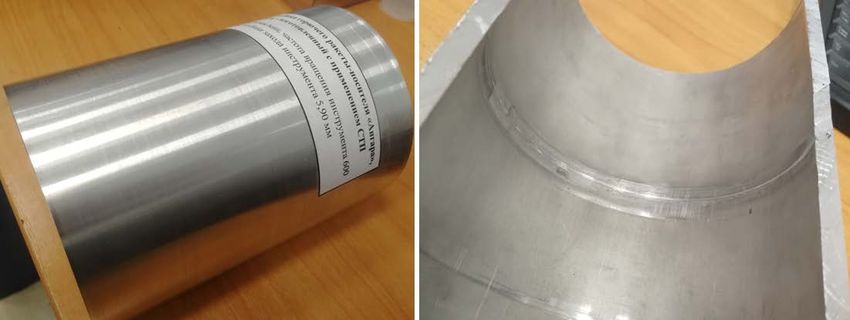
AMSD-2019 IOP Publishing
Journal of Physics: Conference Series 1441 (2020) 012090 doi:10.1088/1742-6596/1441/1/012090

more). An important feature of specialized machines for FSW is that the spindle head has the ability to
rotate in a small range of angles. The need for a rotary spindle head is due to the fact that for the
formation of a sound welds, it is necessary to provide tool tilt angle. The tool tilt angle can range from
2 to 5 º depending on alloy and tool geometry. For example, in the above research [6], the welds were
made with a tool tilt angle of 2 and 2.5 º with a workpiece diameter of 38 mm; in a research conducted
by Russian scientists at SUSU [9], the tool tilt angle was also set at 2 º with a larger diameter of the
workpieces. The availability of a rotary spindle head is not always justified, since a non-rotary spindle
head has greater stiffness and lower cost. In the case of welding girth joints of small-dimension
workpieces (up to 1 m), the necessary tool tilt angle can be “artificially” created, which will allow
welding on three-axis CNC vertical milling machines, that are not equipped with a rotary spindle head.

2. Formulation of the problem
The aim of this study is to obtain friction stir welded aluminum alloy AMg6 pipes with 112 mm outer
diameter and 6 mm wall thickness, and also solid blanks with 118 mm outer diameter using a three-
axis vertical milling machine, then check their quality and develop a list of recommendations for
welding small-dimension girth joints using machine with no rotary spindle head.
The experiments will carried out using vertical milling machine. A drawing of a tool installed in a
Weldon Ø20 holder with a DIN 40 cone is shown in Fig. 1. The tool used in the current article is made
of 45CrMoWSi (~0.45% C, ~1% Cr, ~1% Mo, ~1% W, ~1% Si and others) heat treated steel with the
design geometry of VNIIALMAZ JSC for FSW aluminum alloys with a thickness of 6 mm. The
scheme for welding pipe workpieces is shown in Fig. 2. Welding of solid workpieces will be carried
out according to a similar scheme, but with the absence of backing anvil 2.

 Figure 1. FSW tool used in research

 2

AMSD-2019 IOP Publishing
Journal of Physics: Conference Series 1441 (2020) 012090 doi:10.1088/1742-6596/1441/1/012090

 Figure 2. Scheme for welding pipe workpieces: a) position before welding; b) position during
 welding. 1 – Pipes to be welded, 2 – backing anvil, 3 – FSW tool, 4 - holder.
According to the welding scheme, when the tool tilt angle is zero (Fig. 2), the parts 1 are nonmovable
mounted on a rotating backing anvil 2. The FSW tool 3 is mounted in the holder 4. The axis of the
tool, rotating with a speed Si (rpm), coincides with the junction plane (for example, pipes). At the
beginning of welding, a rotating tool plunging at a speed of Fpl (mm/min) into the parts to a depth
equal to 80-95% of the length of the pin. After the tool has plunged to the required depth, the parts are
rotated at a speed of Fd (deg/min) or Flin (mm/min) in any direction.

3. Theory
Since the overwhelming majority of milling machines the feed rate of rotatory table is set in deg/min,
it is necessary to transform the linear welding speed into angular. For this, the following equation can
be used:

 = 3.14∙ ∙ 360°, deg/min (1)
where Flin is linear welding speed, mm/min; D is the outer diameter of the workpiece.
According to the scheme described above, direct provision of the tool tilt angle is impossible;
therefore, an alternative welding scheme can be used – welding with tool offset in the junction plane
(Fig. 3).

 3
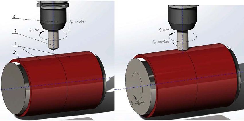
AMSD-2019 IOP Publishing
Journal of Physics: Conference Series 1441 (2020) 012090 doi:10.1088/1742-6596/1441/1/012090

 Figure 3. Welding with tool offset in the junction plane
According to this scheme, the tool has offset by a value that will provide an inclination of the tool axis
to the plane tangent to the parts to be welded, equal to 1–5 º. The offset depends on the radius of the
parts to be welded and the tool tilt angle that must be ensured. The side of offset is depends on the
direction of rotation of the parts. The offset value calculation scheme showed in Fig. 4. In the scheme,
the offset t (OAx) will be equal to the projection of the vector OA onto the abscissa. The length of the
vector (offset t) is calculated by the equation:
 = (90° − ) (2)
where OAx is the offset value (t); OA is the outer diameter of workpieces; α is the tool tilt angle.

 4
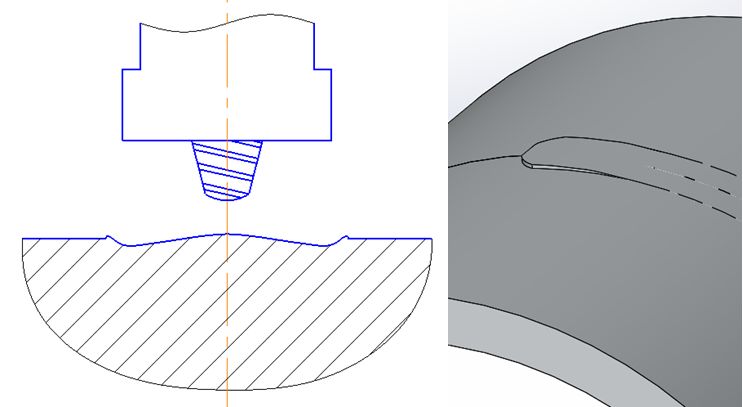
AMSD-2019 IOP Publishing
Journal of Physics: Conference Series 1441 (2020) 012090 doi:10.1088/1742-6596/1441/1/012090

 Figure 4. The offset value calculation scheme
The significant problem of girth welding of small dimension parts is the small contact area between
shoulder and parts to be welded (Fig. 5), which, as known, has a direct impact on the weld quality.

 Figure 5. Tool offset when welding small dimension parts
The contact area of the between shoulder and parts (Fig. 5) will depend on the offset value (and
thereafter on the tool tilt angle). To ensure the optimal contact area, it is necessary to find the optimal
tool offset value experimentally, or to change the shape and dimension of the shoulder until the
required quality is achieved.

4. Experimental results
The welds manufactured using the above scheme are shown in Fig. 6, 7. Welding was carried out at a
tool rotation speed of 600 ... 710 rpm and a travel speed of 40 ... 60 mm / min on various samples.

 5
AMSD-2019 IOP Publishing
Journal of Physics: Conference Series 1441 (2020) 012090 doi:10.1088/1742-6596/1441/1/012090

 а) b)
 Figure 6. FSW of the solid blank: a) – with zero offset (the tool tilt angle 0 °); b) – with offset
 value in proportion to the tool tilt angle 2 °

 Figure 7. FSW of the pipes with tool tilt angle 2 ° after scraping bright: a) face; b) backside

5. Discussion
When welding girth joints of small dimension parts, two defects are observed that are not observed in
linear welding. One of them is a barrel form section of the weld (Fig. 8, a). This defect is characterized
by a lower weld edges according to the outer diameter level of the workpiece in cross section, while
the central part is located at or above the outer diameter level. The occurrence of a barrel form defect
can be explained by the uneven tool and shoulder plunging due to the small outer diameter of parts. In
this case, plunging can be optimized only by tool size adjusting to the optimum value, which will
allow obtaining a high-quality weld. It is impossible to completely eliminate the barrel form defect
when welding small dimension parts, but it can be minimized. In the process engineering of welding

 6
AMSD-2019 IOP Publishing
Journal of Physics: Conference Series 1441 (2020) 012090 doi:10.1088/1742-6596/1441/1/012090

small-dimension parts it is necessary to taken this defect into account – it creates a local thinning in
the cross section, which reduces the part strength.
The second defect, characteristic of FSW of small dimension parts, is the occurrence of local overlap
at the end of the weld (Fig. 8, b). When welding small dimension parts, the back side of the shoulder is
in contact with the workpiece, and on the front side there is a gap between the shoulder and the
workpiece. During welding, the plasticized material is pushed out by the pin, fills the gap and
solidifies at the end of the weld when the tool lifts. This defect can also be eliminated by tool size
adjusting, but this is also not always advisable. During tool travel, this gap is also the field in which
the flash may lift and then formed along the weld edges.
The occurrence of these defects is also observed at the specimens in the research [8].

 а) b)
 Figure 8. Defects characteristic of FSW of small dimension parts: a) – barrel form section; b) –
 local overlap at the end of the weld
Welding modes (tool rotation and travel speed) for friction stir girth welding can be setting as for
linear welding. Much attention needs to be paid to rigidity of equipment for fixing parts. In the case of
linear welding, the parts are rigidly set on the backing anvil, and when welding pipes, special
equipment must be used as the backing anvil. It is also necessary to use steadyrests or other devices to
prevent deformation of parts. The pipes or solid blanks, the outer diameter of which will coincide with
the inner diameter of the parts, or special adjustable equipment can be used as backing anvil, and the
second is preferable, since the pipes may deform during welding. Due to the axial force of the tool on
the pipes, inner diameter of last one decreases caused of deformation, and it leads to the formation of a
fixed joint between equipment and workpieces, comparable to an interference fit.

6. Conclusion
The results shows that the friction stir girth welding using vertical milling machine with non-rotary
spindle head is possible with a tool offset. The offset value is set depending on the required tool tilt
angle (similar to linear seams). The experimental results showed that for the manufacture of sound
joints of the aluminum alloy AMg6 with a diameter of 100–120 mm, the optimal tool tilt angle is 2 ...
4 º. Further, in-depth study of the welding process will be carried out using the scheme (Fig. 3), as
well as the occurrence of defects (Fig. 8) and their elimination methods.

References

 7
AMSD-2019 IOP Publishing
Journal of Physics: Conference Series 1441 (2020) 012090 doi:10.1088/1742-6596/1441/1/012090

[1] Sizova O, Shlyakhova G, Kolubaev A, Kolubaev E, Psakhie S, Rudenskii G, Chernyavsky A
 and Lopota V 2014 Microstructure features of aluminum alloys welded joint obtained by
 friction stir welding Advanced Mat. Res. 872 174–9
[2] Padhy G K, Wu C S, Gao S 2018 Friction stir based welding and processing technologies –
 processes, parameters, microstructures and applications: A review J. of Mat. Science & Tech
 34 1–38
[3] Gurunath Shinde, Sameer Gajghate, Dr.P.S.Dabeer, Dr.C.Y. Seemikeri 2017 Low Cost Friction
 Stir Welding: A Review Mater. Today. Proceedings 4 8901–10
[4] Antonio Carlos de Oliveira Miranda, Adrian Gerlich, Scott Walbridge 2015 Aluminum friction
 stir welds: Review of fatigue parameter data and probabilistic fracture mechanics analysis
 Eng. Fracture Mechanics 147 243–60
[5] Shachnev S Yu, Pashchenko V A, Makhin I D, Bazeskin A V, Dubovitsky A D 2016 Otrabotka
 tekhnologii svarki treniyem s peremeshivaniyem alyuminiyevykh splavov 1570S, AMG6
 bol'shoy tolshchiny dlya ispol'zovaniya v perspektivnykh razrabotkakh RKK «Energiya»
 (Development of technology for friction stir welding of aluminum alloys 1570C, AMG6 of
 large thickness for use in promising developments of RSC Energia) Space Engineering and
 Technology 4 24–30
[6] Hattingh D G, von Wellighm L G, Bernard D, Susmel L, Tovo R, James M N 2016
 Semiautomatic friction stir welding of 38 mm OD 6082-T6 aluminium tubes J. of Mat. Proc.
 Tech. 238 255–66
[7] Binxi Chena, Ke Chena, Wei Hao, Zhiyuan Lianga, Junshan Yao, Lanting Zhanga, Aidang Shan
 2015 Friction stir welding of small-dimension Al3003 and pure Cu pipes J. of Mat. Proc.
 Tech. 223 48–57
[8] Chernykh I K, Vasil’ev E V, Matuzko E N, Krivonos E V 2018 Upgrading weld quality of a
 friction stir welded aluminum alloys AMп6 Journal of Physics: Conf. Series. 944 1–9
[9] Safin V N, Shchurov I A and Fedorov V B 2012 Otrabotka tekhnologii svarki treniyem s
 peremeshivaniyem dlya soyedineniya trub iz alyuminiyevykh splavov (Development of
 friction stir welding technology for joining pipes from aluminum alloys) Bulletin of SUSU.
 Series "Engineering" 33 117–21

 8
You can also read