Joining of ultra-high-strength steels using resistance element welding on conventional resistance spot welding guns
←
→
Page content transcription
If your browser does not render page correctly, please read the page content below
Welding in the World
https://doi.org/10.1007/s40194-021-01122-2
RESEARCH PAPER
Joining of ultra-high-strength steels using resistance element
welding on conventional resistance spot welding guns
Heinrich Günter 1 & Gerson Meschut 1
Received: 8 September 2020 / Accepted: 31 March 2021
# The Author(s) 2021
Abstract
Single-step joining of dissimilar material combinations between ultra-high-strength steels and high-strength aluminium alloys
with sufficient mechanical joint properties by using conventional resistance spot welding equipment has not been reported yet. In
this research paper, a novel single-step joining technology, so-called self-penetrating resistance element welding, is introduced.
First, the motivation for this novel joining technology, the state of the art in joining, and the process characteristics are presented.
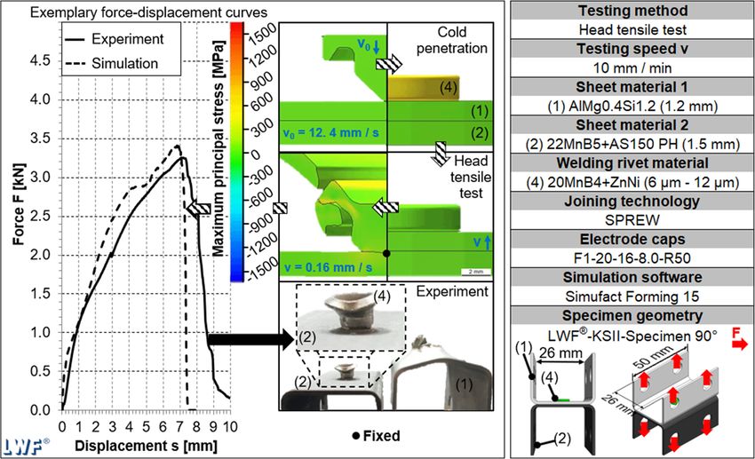
In the results section, the welding rivet geometry is first determined using forming simulations and validated by head tensile tests.
Followed by the description of the welding process and its characteristics, the mechanical joint properties are reported. The results
show that a numerically optimised welding rivet geometry can guarantee sufficient joint strength. By this welding rivet geometry,
a thermally assisted penetration of aluminium and therefore welding to steel is possible with and without adhesive. Furthermore,
it is shown that the welding process can be designed by means of simulations. Finally, the shear tensile tests prove that an overall
sufficient joint strength is ensured.
Keywords Multi-material design . Ultra high-strength steel . High-strength aluminium . Resistance element welding . Joining
process simulation
1 Introduction this reason, mechanical joining and adhesive bonding are
widely applied for joining dissimilar materials in multi-
In order to meet the legal requirements [1] for pollutant emis- material design [4]. However, the use of mechanical and ad-
sions, most of the automotive manufacturers use lightweight hesive bonding requires additional investments (e.g. equip-
design and materials to reduce the car body weight [2]. In ment investment, additional personnel, training), reducing
body-in-white manufacturing, materials such as ultra-high- the cost-effectiveness of multi-material design [5]. A possible
strength steels, high-strength aluminium alloys, and fibre- solution is the reutilisation of the already existing joining
reinforced plastics are suitable for this purpose [3]. The equipment. By combining the mechanical (riveting) and ther-
targeted mixing of these materials is referred to as multi- mal (welding) joining principles, a new joining technology
material design. Joining of dissimilar materials by using ther- called resistance element welding (REW) is created. REW
mal joining technologies (e.g. arc welding, laser welding, re- enables the multi-material design in mass production since
sistance spot welding) is highly challenging due to significant conventional resistance spot welding (RSW) equipment can
differences in the material-physical properties (e.g. melting be used. REW can be understood as a thermal-mechanical
points, thermal conductivities, electrical resistances) [4]. For joining technology which combines the advantages of me-
chanical (form-fit) and thermal (metallic bond) joining princi-
Recommended for publication by Commission III - Resistance Welding, ples and enables a boundary stretch of joining dissimilar ma-
Solid State Welding, and Allied Joining Process terial combinations. The two-step version of REW is investi-
gated in several research papers and dissertations [6 – 13]. In
* Heinrich Günter this case, the welding rivet (steel) is punched into the light-
Heinrich.Guenter@lwf.upb.de weight construction material (aluminium/plastic) first, and in a
second step, this welding rivet is welded to a steel sheet. In
1
Laboratory for Material and Joining Technology (LWF), Paderborn between these two steps, the aluminium or plastic must be
University, Paderborn, Germany transported to the steel structure. In [6], the two-step REW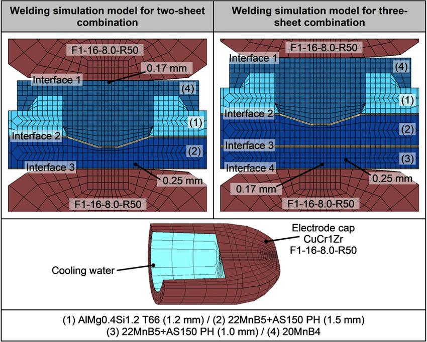
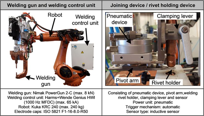
Weld World

using a welding rivet with a countersunk head is developed. In      (aluminium to steel), RSW is only suitable for fixing/bonding
[7], a two-step process is developed, in which the first step       and does not work with additional adhesive [25]. Figure 1
operates free of protruding. In [8], a two-step joining process     shows the body in white of the Audi A6 C8 (left) beside
using a welding rivet which gets formed during punching is          exemplary joining tasks and the corresponding joinability by
developed. In [9], a semi-hollow welding rivet according to         SPR and REW (right). All joints are either not or only restrict-
self-pierce riveting (SPR) is developed and welded to the steel     edly joinable by SPR. By the use of REW, these joints expe-
sheet. In [10], a short-time (≤ 20 ms) welding process is in-       rience a significantly increased joinability.
vestigated. In [11], the shear tensile-properties are analysed.        Two-step REW was initially applied in mass production of
The joinability of magnesium to stainless steel and the             car bodies within the Volkswagen Passat B8 [27]. In this re-
joinability of aluminium to ultra-high-strength steel are stud-     search paper, the advanced version of two-step REW, so-
ied in [12, 13], respectively. Since the idea of reducing the car   called self-penetrating resistance element welding (SPREW),
body weight is old [14], the first application of multi-material    is presented and described in detail. Figure 2 shows the pro-
design in mass production was implemented in the Ford               cess sequence of SPREW, which can be divided into three
Model T (comparing Ford Model T from 1915 to Ford                   subprocess steps. Within the first step, the sheets and the
Model T from 1925) [15]. In series production of the Audi           welding rivet are positioned between the electrode caps. A
A8 D2 (1994–2002), the Audi Space Frame (ASF) enabled a             holding force is built up, which causes the welding rivet tip
body in white made of aluminium [16]. In this case, mechan-         to partially penetrate the aluminium sheet. For a further pen-
ical (riveting, clinching, screwing, and hemming), adhesive         etration of the aluminium sheet, it is necessary to soften the
bonding, and hybrid (riveting + adhesive bonding) joining           aluminium by Joule heating. This process step is referred to as
technologies were used [17]. Adhesive bonding is widely used        hot penetration [16, 28, 29]. Due to the current flow, the steel
in body in white manufacturing due to its flexibility in joining    sheet and the welding rivet are heated up, and the aluminium
similar and dissimilar materials, its low requirements for ac-      sheet softens due to the heat absorption [30]. The thermally
cessibility, and its simple process sequence [18]. Otherwise,       induced softening of the aluminium enables a full penetration
significant disadvantages remain in surface pre-treatment, ad-      of the aluminium sheet. After hot penetration, the welding
hesive curing, non-destructive testing, and strength under peel     process starts by welding the welding rivet tip to the steel
tensile load [18, 19]. Mechanical joining technologies, e.g.        sheet. During the welding process, the molten nugget grows
clinching or SPR, are commonly used for joining materials           into the welding rivet shank, and a metallic bond between the
with lower strength and higher ductility [20]. Clinching is a       welding rivet and the steel sheet is created [31].
mechanical joining technology which enables form-locked
joints without any additional auxiliary joining element.
Conventional clinching is only suitable when the joined ma-         2 Experimental procedure
terials are relatively ductile, and the tensile/yield strength is
low [16]. Press-hardened steels in dissimilar joints can only be    2.1 Welding rivet geometries
joined by shear-clinching [21]. SPR is a mechanical joining
technology for joining thicker aluminium sheets by using a          Figure 3 shows the initial welding rivet geometry [16] (left),
semi-hollow rivet [16]. Both clinching and SPR provide a            which is divided into a welding rivet head and a welding rivet
good material-thickness-flexibility and heatless process se-        shank (centre), and the numerically optimised welding rivet
quences [20]. However, these joining technologies have dis-         geometry (right).
advantages in tool-set-frequency and relatively long process
duration compared to RSW [22]. In the Ford F150 Gen. 13, an         2.2 Welding equipment
aluminium car body was implemented by mostly using me-
chanical joining technologies. Comparing the Ford F150 Gen.         Figure 4 (left) shows the welding configuration consisting of a
12 (mostly steel, about 3000 spot welds, and no SPR) to the         robot-mounted welding gun in C-frame design (Nimak
Ford F150 Gen. 13 (mostly aluminium, about 100 spot welds,          PowerGun 2-C) and a 1000-Hz MFDC current source
about 2300 self-pierce rivets, and about 120 clinching joints)      (Harms + Wende Genius HWI) with a constant current control
shows that RSW no longer plays a role in the Ford F150 Gen.         system. The electrode caps, which are water-cooled with a
13 [15]. In general, mechanical and hybrid joining technolo-        minimum flow rate of 4 l/min, are mounted on shafts with a
gies are used when similar aluminium or dissimilar joints are       diameter of 16 mm. In order to ensure a reproducible position-
manufactured [23]. On the other hand, RSW is most widely            ing of the welding rivet, a dedicated welding device is used.
used for the joining of steel-based car bodies [24]. RSW there-     The device illustrated in Fig. 4 (right) is used for this purpose.
fore continues to play a dominant role in body-in-white pro-        The pneumatically driven device can be attached to the elec-
duction, and the vast majority of joining equipment is oriented     trode shaft using a clamping lever. The welding rivet holder is
towards RSW. For joining dissimilar material combinations           attached to the pivot arm, which can be rotated. An inductive
Weld World
Fig. 1 Self-supporting steel body of the Audi A6 C8 utilising a side panel made of steel (left side) [26], and the joinability of selected joints by self-pierce
riveting (SPR) and resistance element welding (REW) (right side)
sensor is attached to the pneumatic device, which triggers the The adhesive is applied automatically on the aluminium sheet
pivot arm to move the welding rivet holder back to the initial with a layer thickness of approx. 0.3 mm without pre-treat-
position. ment. Table 2 shows the physical and mechanical properties
of the adhesive.
3 Test materials
3.1 Simulation models
Table 1 shows the chemical and mechanical properties of the
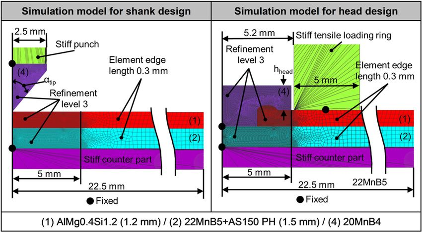
test materials. The 6000 series aluminium alloy AlMg0.4Si1.2 Figure 5 shows the 2D axis symmetric forming simulation
(EN AW-6016) belongs to the group of heat-treatable wrought models for welding rivet design realised in Simufact®
alloys. The aluminium is welded in the T4 condition and test- Forming 13 (Hexagon Corporate Services Ltd./MSC
ed in the T66 condition by heating up the specimens to 180°C Software GmbH). The left simulation model for shank design
for 30 min. This heat treatment simulates the dip-painting is used to determine the optimum tip angle (αtip). Here, the
process [17]. The steel alloy 22MnB5 is a press-hardenable, punch is moved down towards the aluminium sheet and is
boron-alloyed steel which is characterised by an ultra-high fixed to the shank. The right simulation model for head design
strength in heat-treated condition [32]. The steel alloy is needed to determine the optimum head height (hhead). In
20MnB4 is mainly used for auxiliary joining parts, such as contrast to the simulation model for shank design, here, a stiff
screws and rivets, and has similar chemical, thermal, and elec- tensile loading ring is fixed to the aluminium sheet. In order to
trical properties as the 22MnB5. simulate a head-tensile load case, the loading ring is moved
The used adhesive is a one-component, heat-curing, epoxy- upwards. In addition, the welding rivet is fixed to the steel
based adhesive especially developed for the body shop [33]. sheet.
Fig. 2 Process sequence of self-penetrating resistance element welding (SPREW)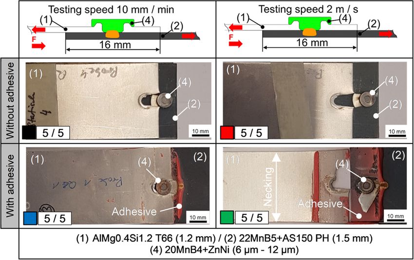
Weld World

Fig. 3 Initial welding rivet geometry (left), subdivided in welding rivet head and shank (centre), and the numerically optimised welding rivet geometry
(right)

   Figure 6 shows the used 3D welding simulation models                       4 Results
implemented in Sorpas® 3D. The models are used to deter-
mine the temperature fields and the dynamic resistances dur-                  4.1 Welding rivet design
ing welding. In this case, only the welding process is simulat-
ed since hot penetration cannot be simulated within 3D due to                 In this section, the optimised welding rivet geometry (Fig. 3,
missing damage criteria in the computational model. The sim-                  right) is determined using forming simulations. Finally, this
ulation models consist of an upper electrode, an already                      welding rivet geometry is verified using numerical and exper-
inserted welding rivet, a pre-holed and formed aluminium                      imental head tensile tests. Figure 7 shows results of forming
sheet, one or two steel sheets, and a lower electrode. The                    simulations for shank design. The diagram includes results of
electrode cap (CuCr1Zr) geometry F1-16-8.0-R50 corre-                         the minimum deformation energy (W = F ∙ Δl), which is ap-
sponds to the geometry which is used in the experiments                       plied to move the punch towards the aluminium sheet to its
and is therefore water-cooled (see lower section in Fig. 6).                  final position (Δlfinal) and simultaneously deform the shank.
Between each object, an interface is included. Three and four                 Furthermore, the diagram includes the minimum punching
interfaces are included in the welding simulation model for                   force, which is needed to move the shank to its final position.
two-sheet application and in the model for three-sheet appli-                 The diagram illustrates that the deformation energy is decreas-
cation, respectively.                                                         ing, while the tip angle (αtip) is increasing. This circumstance

Fig. 4 Welding gun and control unit mounted on an industrial robot (left) and the pneumatic joining device developed especially for SPREW (right)
Weld World

Table 1    Chemical composition and mechanical properties of the investigated materials

Material               Weight [%]                                                                                                         Rm [MPa]      A [%]

                       Al         B            C        Cr      Cu           Fe       Mg       Mn       Mo       Si     Ti          Zn

AlMg0.4Si1.2 T4        96.55      -            -        0.1     0.2          0.5      0.6      0.2      -        1.5    0.15        0.2   250           24
AlMg0.4Si1.2 T66                                                                                                                          300           10
22MnB5 PH              0.05       0.1          0.25     0.2     0.1          97.6     -        1.5      0.1      0.3    0.05        -     1550          6
20MnB4                 -          0.05         0.23     0.3     0.25         97.67    -        1.2      -        0.3    -           -     520           14

arises due to the condition of constant shank volume, and thus                       the aluminium sheet. Head deformation no longer occurs
the total length of the shank decreases. The minimum                                 when the head height is greater than 1.5 mm. The force de-
punching force is increasing while the tip angle is also increas-                    creases, the energy absorption stagnates, and the failure occurs
ing. In this case, shanks with larger tip angles generate less                       exclusively in the aluminium sheet. Due to higher energy
cutting effect, which means that higher forces are necessary to                      absorption, a head deformation is tolerated when the final
penetrate the aluminium sheet. Due to the opposing curves, it                        failure occurs in the aluminium sheet. The optimum head
can be assumed that the shank length reduction, resulting from                       height can be read from the diagram at 1.1 mm. In this case,
the tip angle increase, has a greater effect on the energy ab-                       a force of approx. 2.9 kN and an energy absorption of approx.
sorption than on the minimum punching force. Looking at the                          7.7 J can be achieved.
corresponding images (centre), the aluminium sheet lifts while                           Figure 9 shows forming simulations which verify the nu-
the tip angle increases. In this case, higher tip angles block the                   merically optimised welding rivet geometry. Compared to the
radial material flow during penetration, and therefore, the                          initial welding rivet geometry, the head diameter is reduced
displaced material cannot move laterally, and a gap emerges                          from 10.0 to 9.0 mm, and the shank diameter is reduced from
between the aluminium and the steel sheet. This gap can lead                         5.0 to 4.5 mm, which results in a weight reduction from 1.24
to the kissing bond effect and should be kept as small as                            to 0.81 g. The volume of the ring groove under the rivet head
possible. Furthermore, Fig. 7 shows that a full displacement                         is increased to 110% of the shank volume. The top simulation
of the aluminium is not possible when a tip angle of 90° is                          figure illustrates the welding rivet penetrating the aluminium
chosen, and therefore, the shank gets deformed unfavourably.                         sheet in cold state. Here, a tensile load is applied in the
The aim of this numerical shank design is to optimise the tip                        welding rivet head. In the figure below, the head is deformed
angle for an optimum penetration process with low forces, low                        due to the head tensile load, and finally, a failure occurs in the
deformation energy, and a small gap between the aluminium                            aluminium. The exemplary force-displacement curves show a
and the steel sheet. For this reason, a tip angle of 45° should be                   good conformity between forming simulatio n (without previ-
chosen, which allows a full penetration of the aluminium with                        ous applied head tensile load) and experiment. The resulting
a small gap of 0.7 mm, a low minimum punching force of 3.0                           fracture pattern also illustrates a head deformation due to the
kN, and a deformation energy of 16.3 J.                                              head tensile load and the failure in the aluminium.
   Figure 8 shows the results of simulated head tensile tests
for head design. The diagram includes the results of the de-                         4.2 Dynamic resistances and temperature fields
formation energy/energy absorption and the maximum force.
At a head height (hhead) of up to 0.9 mm, head failure occurs,                       In this section, the resulting dynamic resistances and temper-
which rapidly reduces the energy absorption and the force,                           ature fields during welding are described. Figure 10 (left)
wherefore a head failure must be avoided. At a head height                           shows the dynamic resistance curves from the experiments
between 1.1 and 1.5 mm, the force increases due to the in-                           and simulations. The illustrated cross-sections (etched for
creasing head tensile stiffness. In parallel, the total displace-                    15 s in 3% alcoholic nitric acid HNO3) (centre) from the
ment decreases, which results in less energy absorption. In this                     experiments are compared to the simulated ones. The welding
case, the head gets deformed, and the failure mode occurs in                         parameters (current, electrode force, welding time) for the

Table 2 Physical and mechanical
properties of the adhesive [33]          Colour       Density         Viscosity       Stress at break       Strain at        Lap shear           Peel strength
                                                      [kg/m3]         [Pas]           [MPa]                 break [%]        strength [MPa]      [MPa]

                                         Red          1230            ≥ 30            29                    11               ≥ 29                11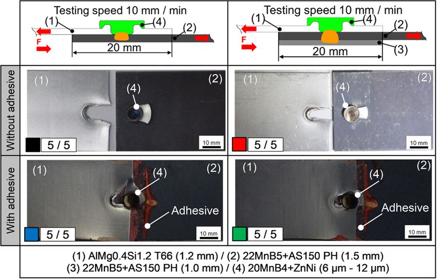
Weld World

Fig. 5 Forming simulation model for shank design (left) and forming simulation model for head design (right), realised in Simufact® Forming 13
(mechanical joining tool)

Fig. 6 Welding simulation model for two-sheet combination (upper left) and welding simulation model for three-sheet combination (upper right),
realised in Sorpas® (3D welding tool)
Weld World

Fig. 7 Results of forming simulations for shank design including an analysis of relevant magnitudes (left), some figures of simulation results (centre),
and relevant test information (right)

welding simulation were selected in accordance with the ex-                    (according to Fig. 2). The simulated dynamic resistance
periments. In these cases, only a single current pulse without                 curves (shown in Fig. 10, left) are not divided into these sub-
any up- or downslopes was selected to guarantee a simple                       sequences since the welding rivet is already located in its final
process control. The dynamic resistance curves from the ex-                    position. Between 200 and 260 ms, a drop in the dynamic
periments are divided into hot penetration and welding                         resistance curves (experiments and simulations) can be

Fig. 8 Results of forming simulations for head design including an analysis of relevant magnitudes (left), simulation results (centre), and relevant test
information (right)
Weld World

Fig. 9 Results of forming simulations including force-displacement-curves (left), simulation results (centre), and relevant test information (right)

detected. The reason for this drop is the reduction in contact                 material resistance of aluminium, and the dynamic resistance
resistances. In the experimental resistance curves of SPREW,                   curve drops again. The final position of the welding rivet is
there is a short increase from 260 to 300 ms. The arrangement                  reached at 340 ms. Now, the molten nugget expands from the
and shape of the electrodes concentrate the current flow in the                steel sheet into the welding rivet. The simulated dynamic re-
steel sheet. This creates a molten zone in the steel first, in-                sistances increase between 260 and 350 ms because the weld
creasing the resistance. At 300 ms, the welding rivet head                     nugget is created, and it expands from the steel sheet into the
touches the aluminium sheet, a shunt occurs due to lower                       welding rivet. Due to the missing hot penetration in

Fig. 10 Experimental and simulated dynamic resistances (left), cross-sections and simulation results (centre), and relevant test information (right)
Weld World
simulation, the simulated dynamic resistance curves differ green), which is mainly included in steel sheet and welding
from the experimental ones by up to 320 ms. However, the rivet, and the aluminium (Al = red) are sharply separated from
shape is very similar, and at 320 ms, the experimental and each other. Only a very thin layer, which arises from alumin-
simulated dynamic resistance curves are superimposed. The ium oxides (AlSi-coating), is visible between the welding riv-
comparison of experimental and simulated cross-sections il- et and the steel sheet. This thin layer defines the geometrical
lustrates that the molten zones in steel and aluminium only notch (areas A and B) since in this area, a full weld cannot be
show minor deviations. For this reason, it can be assumed that expected. However, this layer is much thinner than the AlSi-
the temperature fields in the experiments correspond to the coating and therefore cannot be replaced during hot penetra-
simulated ones. tion and welding.
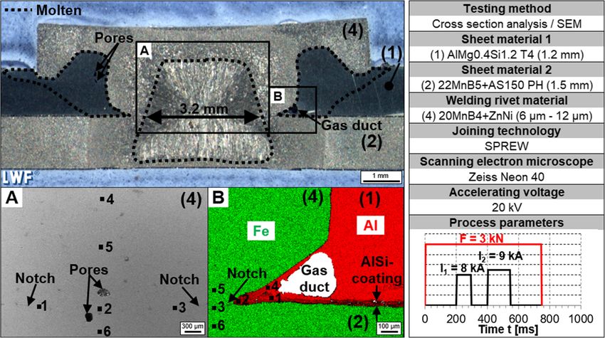
Table 3 lists the points ▪1 to ▪6 from the SEM figures A and
4.3 Metallurgical joint properties and chemical B in Fig. 11. The table contains the weight and the atomic
composition percentages of aluminium (Al), iron (Fe), and silicon (Si).
Other elements are also detected, but for the sake of a clear
In this section, the metallurgical structure of the joint and the arrangement, they are not illustrated in this table. Point ▪4 in
chemical composition within the welding nugget and outside the SEM figure A is furthermost from the virtual separating
the shank are described. Figure 11 shows a two-sheet joint line and illustrates the lowest Al-content within the welding
which is welded with higher energy input. The cross-section nugget at 0.11% (compared to table 1, Al = 0% to 0.05%).
contains two areas, A and B, which are examined with a scan- Points ▪1 and ▪3 are the closest to the virtual separating line
ning electron microscope (SEM) and are illustrated in detail and include the highest Al-content of 0.21% and 0.24%, re-
below. The cross-section illustrates a high welding nugget spectively. It can therefore be assumed that small proportions
penetration within the welding rivet and a greater molten area of Al-atoms diffuse into the steel due to the proximity to the
in the aluminium (compared to figure 10) due to the higher notch. Above the virtual separating line at point ▪5, the Fe
energy input. The higher energy input leads to pores (left side content is the lowest at 94.2%. The reason for this low Fe
from shank) and a gas duct (lower right from shank) within the content in this area is a relatively high carbon (2.64 weight-%,
aluminium. Furthermore, the slight head penetration in the 10.78 atom.-%) and a relatively high oxygen (1.30 weight-%,
aluminium is also caused by the molten aluminium under 4.00 atom.-%) content. These high contents occur due to
the head. The figure from the SEM in area A shows slight carburisation during press-hardening [34]. In figure B, points
imperfections (pores). Aluminium inclusions can be detected ▪5 and ▪6 include Al-contents of 0.16% and 0.22%, respec-
at the geometric notches, which define the nugget diameter. tively. Point ▪3 shows proportions of Al 6.2%, Si 2.19%, and
The figure from the SEM in area B shows a small gas duct. Fe 89.02%. The proportions of Al and Si indicate that the
The SEM figure of area B illustrates that the ferrite (Fe = AlSi-coating is diffused into the steel, compared to the
Fig. 11 Cross-section of SPREW joint (upper left), figures from the SEM within the weld (A) and outside the weld (B), and relevant test information
(right)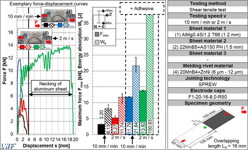
Weld World
Table 3 Chemical composition
inside the welding nugget (A) and Energy dispersive X-ray spectroscopy [weight-%/atom.-%]
outside the welding rivet shank
(B), indicating the weight- and A B
atomic-percentage
Al-K Fe-K Si-K Al-K Fe-K Si-K
Point ▪1 0.24/0.47 96.76/90.12 0.25/0.46 61.41/72.44 34.35/19.58 1.18/1.33
Point ▪2 0.19/0.38 97.02/92.69 0.23/0.45 47.31/57.30 45.49/26.62 0.79/0.92
Point ▪3 0.21/0.41 97.11/92.86 0.38/0.72 6.20/11.17 89.02/77.48 2.19/3.78
Point ▪4 0.11/0.21 96.86/91.06 0.37/0.69 96.90/96.45 1.33/0.64 -/-
Point ▪5 0.19/0.35 94.20/82.89 0.55/0.96 0.22/0.42 96.70/89.89 0.29/0.53
Point ▪6 0.16/0.31 96.27/89.74 0.33/0.60 0.16/0.31 98.10/93.65 0.33/0.62
interdiffusion layer in [35]. At point ▪4, the Al-content is the 12.86 kN can be achieved and are therefore also similar. In
highest at 96.9%, and a low Fe content of 1.33% is visible. terms of energy absorption, the trend is reversed compared to
This suggests that some Fe atoms have diffused into the alu- the elementary joints, whereupon the energy absorption of the
minium sheet. Points ▪1 and ▪2 are located on the AlSi layer. three-sheet joints 29.97 J is less compared to the energy ab-
Noticeably, the Si content is relatively low—with 1.18% and sorption of the two-sheet joints 34.40 J. Overall, it can be
0.79%, respectively—compared to the initial content of stated that the two- and three-sheet joints have very similar
approx. 10%. This fact indicates a diffusion of Si into the values, and significant differences are not present.
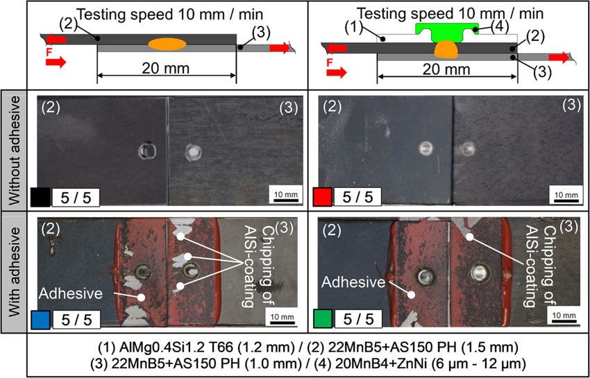
aluminium sheet, but this is not proven here. Overall, it can Figure 13 shows the resulting fracture patterns of shear ten-
be stated that the molten aluminium is completely displaced sile tests for two- (left section) and three-sheet (right section)
during hot penetration, and only the AlSi-coating gets dis- joints with (lower section) and without (upper section) adhe-
solved within the welding nugget. sive. In this case, the elementary joints fail by bearing deforma-
tion of the aluminium sheet (10/10). The hybrid joints also fail
4.4 Mechanical joint properties by bearing deformation of the aluminium sheet (10/10).
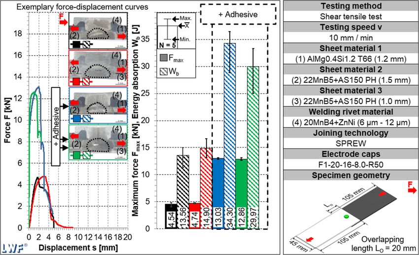
Figure 14 shows the results of quasi-static and crash shear
In this section, the results of shear-tensile tests according to tensile tests (aluminium-steel joints) with a reduced overlap-
DVS/EFB 3480-1 under quasi-static (10 mm/min) and crash ping length of 16 mm. The bar chart illustrates that the ele-
load (2 m/s) with two different overlapping lengths (16 mm mentary joints, which are tested under quasi-static load, can
and 20 mm) are presented. The quasi-static tensile specimens achieve a maximum force of 3.20 kN and an energy absorp-
(free clamping length of 95 mm) are tested on a static testing tion of 8.13 J. The elementary joints, which are tested under
machine (Zwick100) by ZwickRoell, and the crash tensile crash load, can achieve a maximum force of 5.27 kN and an
specimens are tested on a crash testing machine (VHS 65/ energy absorption of 11.74 J. Considering the hybrid joints,
80-20) by Instron. All five specimens per material combina- which are tested under quasi-static load, the maximum force
tion (5 specimens ∙ 12 material combinations = 60 specimens) increases to 11.79 kN, and the energy absorption increases to
are welded with the same process parameters, which are 21.64 J. The hybrid joints, which are tested under crash load,
shown in Fig. 10 (I = 6 kA, t = 300 ms, F = 3kN). Figure 12 show that the maximum force increases to 13.82 kN, and the
shows the results of quasi-static shear tensile tests energy absorption increases to 150.93 J. This increase can be
(aluminium-steel joints) with an overlapping length of 20 described by the necking of the aluminium sheet.
mm. The left section illustrates exemplary force- Figure 15 shows the resulting fracture patterns of shear
displacement curves for two- and three-sheet combinations tensile specimens under quasi-static load (left section) and
with (hybrid) and without (elementary) adhesive as well as crash load (right section) with (lower section) and without
four cross-sections for the definition of the force application (upper section) adhesive. The elementary joints fail by bearing
points. The middle section illustrates the maximum testing deformation of the aluminium sheet (10/10). The hybrid joints
forces Fmax and the resulting energy absorption Wb in a bar also fail by bearing deformation of the aluminium sheet (10/
chart. The bars for elementary two- and three-sheet joints 10), and the necking of the aluminium sheet is visible (lower
show maximum forces of 4.54 kN and 4.74 kN, respectively. right).
Furthermore, the bar chart illustrates that the energy absorp- Figure 16 shows the results of quasi-static shear tensile
tion of the two-sheet joints 13.56 J is slightly lower compared tests (steel-steel joints) with an overlapping length of 20
to the three-sheet joints 14.90 J. The bars for hybrid two- and mm. The bars for elementary two- and three-sheet joints show
three-sheet joints show that maximum forces of 13.03 kN and maximum forces of 15.73 kN and 17.32 kN, respectively.Weld World Fig. 12 Results of shear tensile tests for aluminium-steel joints (overlap- without adhesive (left), the achievable maximum forces and energy ab- ping length 20 mm) under quasi-static load including exemplary force- sorptions (centre), and relevant test information (right) displacement curves for two- and three-sheet combinations with and Furthermore, the bar chart illustrates that the energy absorp- three-sheet joints show that maximum forces of 31.81 kN and tion of the two-sheet joints 3.46 J is slightly lower compared 34.07 kN can be achieved. In terms of energy absorption, the to the three-sheet joints 4.27 J. The bars for hybrid two- and trend is the same compared to the elementary joints, Fig. 13 Fracture patterns of aluminium-steel shear tensile specimens (overlapping length 20 mm) tested under quasi-static load for two- (left section) and three-sheet (right section) combinations without (upper section) and with (lower section) adhesive
Weld World

Fig. 14 Results of shear tensile tests (overlapping length 16 mm) under        achievable maximum forces and energy absorptions (centre), and relevant
quasi-static and crash load including exemplary force-displacement             test information (right)
curves for two-sheet combinations with and without adhesive (left), the

whereupon the energy absorption of the two-sheet joints                        differences are not present. Furthermore, it can be concluded
5.05 J is less compared to the energy absorption of the three-                 that adhesive leads to an increase of maximum force by
sheet joints 6.34 J. Overall, it can be stated that the two- and               approx. 100% and to an increase of energy absorption by
three-sheet joints have very similar values, and significant                   approx. 47%. Comparing the energy absorption of hybrid

Fig. 15 Fracture patterns of aluminium-steel shear tensile specimens (overlapping length 16 mm) tested under quasi-static (left section) and crash (right
section) load for two-sheet combinations without (upper section) and with (lower section) adhesive
Weld World

Fig. 16 Results of shear tensile tests for steel-steel joints (overlapping       without adhesive (left), the achievable maximum forces and energy ab-
length 20 mm) under quasi-static load including exemplary force-                 sorptions (centre), and relevant test information (right)
displacement curves for two- and three-sheet combinations with and

joints with the results from Fig. 12, it is obvious that adhesive                   Figure 17 shows the resulting fracture patterns of shear
does not improve the joint properties as much as it does when                    tensile tests for two- (left section) and three-sheet (right sec-
joining aluminium to steel.                                                      tion) joints with (lower section) and without (upper section)

Fig. 17 Fracture patterns of steel-steel shear tensile specimens (overlapping length 20 mm) tested under quasi-static load for two- (left section) and three-
sheet (right section) combinations without (upper section) and with (lower section) adhesive
Weld World

adhesive. Since the welding nugget diameter of approx.               nugget. However, these amounts can be explained by the
4.9 mm is sufficiently dimensioned, the two-sheet joints fail        diffusion of the AlSi-coating within the molten nugget.
by plug failure mode (10/10). The failure mode of the three-         Finally, the shear tensile tests with different overlapping
sheet joints differs since a shear failure can always be detected    lengths and testing velocities reported that the welding
(10/10). It is likely that this effect is caused by the additional   nugget guarantees a higher joint strength than the form-fit
aluminium layer, thereby increasing the stiffness of the shear       since failure always occurs in the aluminium instead of the
tensile specimen and permitting less peel load. Furthermore,         welding nugget (shear failure). The application of an adhe-
the fracture patterns of hybrid joints show a chipping of the        sive layer could further improve the mechanical joint prop-
AlSi-coating on the steel surface (see Fig. 17 (lower section)).     erties. Under crash-load, the adhesive could improve the
Overall, the adhesive joints fail by cohesion failure, and the       energy absorption by approx. 1185%. It is highly recom-
nugget failure mode is acceptable. Finally, it can be assumed        mended to apply adhesive between aluminium and steel
that the selected process parameters generate sufficient joint       due to its joint improvement, electro-chemical separation,
strengths, and the welding nugget diameters d > 4 ∙ √(tmin =         and electrical insulation. The application of an additional
1.0 mm) are therefore sufficiently dimensioned.                      adhesive layer between steel sheets should be considered
                                                                     optional since the improvement in energy absorption by
                                                                     approx. 47% is relatively low. An improvement in the
5 Discussion                                                         achievable maximum tensile shear forces by approx.
                                                                     100% might potentially justify an additional process step.
For the numerical welding rivet design in cold-state, an             In summary, the results show that SPREW is very well
initial geometry was divided into a head and a shank for             suited for joining mixed joints in two- and three-sheet
excluding mutual interactions. This subdivision allows an            applications.
independent design of experiments (one factor at a time)
and therefore a simplified evaluation. It could be shown
that the tip angle has an influence on the material flow
                                                                     6 Summary
and a gap increase could be detected when tip angles larger
than 40° were used. The forming simulations for head de-
                                                                     In this research paper, it was shown that REW represents a
sign showed that the head height has an influence on the
                                                                     suitable solution to overcome the metallurgical incompatibil-
maximum head tensile force and the resulting energy ab-              ity of dissimilar material compounds. In a large review [36],
sorption. When a head height less than 1.1 mm was used,
                                                                     REW was compared to other welding technologies. In this
the maximum force rapidly decreased. Therefore, head
                                                                     review, REW was seen to provide a high joint quality. It thus
heights larger than 1.1 mm are recommended. The results              represents a promising approach for manufacturing dissimilar
of numerical and experimental head tensile tests showed a
                                                                     joints in multi-material design. In this research paper, the ad-
good accordance. Thus, this approach can be recommend-
                                                                     vanced version of REW, so-called self-penetrating resistance
ed for welding rivet design. Nevertheless, it should be con-         element welding (SPREW), was introduced. First, the welding
sidered that the heat input during hot penetration has an
                                                                     rivet geometry was determined using forming simulations.
influence on shank deformation and metallurgical notches.
                                                                     The welding process and its characteristics as well as the
Therefore, an experimental alignment should always be                chemical composition of the resulting dissimilar joint were
executed. The welding simulations, which were carried
                                                                     described. Finally, the mechanical joint properties were inves-
out to determine the temperature fields and dynamic resis-
                                                                     tigated using shear tensile tests with and without additional
tances, also illustrated a good accordance to the experi-            adhesive. The results showed that the simulations matched the
ments. However, the experimental resistances differed
                                                                     experiments, and the aluminium is fully displaced during hot
from the simulated ones due to missing hot penetration.
                                                                     penetration. The shear tensile tests illustrated that the welding
The typical shunt, which is characterised by a dip in resis-         nugget between the welding rivet and the steel sheets enables
tance curves due to contact between welding rivet head and
                                                                     sufficient joint strengths since failure always occurs in the
aluminium sheet, was not represented in welding simula-
                                                                     aluminium. Furthermore, it was presented that a combination
tions. On the other hand, the resulting molten zones in
                                                                     of one aluminium and two ultra-high-strength steel sheets
aluminium and steel showed a good accordance. Thus,
                                                                     could be joined by SPREW, which is not possible to accom-
the used welding simulation models can be recommended
                                                                     plish within a single step by means of any other joining
for determining nugget diameters and molten zones. The
                                                                     technology.
metallurgical and chemical investigations proved that alu-
minium could be fully penetrated during hot penetration
due to its molten state. Only small amounts of aluminium             Acknowledgements In this research paper, selected results of the funded
(Al) and silicon (Si) were detected within the welding               research projects IGF No. 19215 N (FOSTA P 1054) were presented. The
Weld World
IGF project IGF No. 19215 N (FOSTA P 1054) of the Research in welding-brazing mode and resistance element welded magne-
Association for Steel Application – FOSTA, Sohnstrasse 65, 40237 sium alloy/austenitic stainless-steel joints. Journal of Materials
Düsseldorf was promoted through the AiF under the programme for the Processing Tech. 250:45–54. https://doi.org/10.1016/j.jmatprotec.
promotion of joint industrial research and development (IGF) by the 2017.07.006
Federal Ministry for Economic Affairs and Energy due to a resolution 13. Ling Z, Li Y, Luo Z, Feng Y, Wang Z (2016) Resistance element
of the German Bundestag. welding of 6061 aluminum alloy to uncoated 22MnMoB boron
steel. Materials and Manufacturing Processes 31:2174–2180.
Funding Open Access funding enabled and organized by Projekt DEAL. https://doi.org/10.1080/10426914.2016.1151044
14. Lanzeratz H, Pasligh N (2013) Lightweight design with structural
Open Access This article is licensed under a Creative Commons adhesives and foams. In: Joining Conference, Bad Nauheim.
Attribution 4.0 International License, which permits use, sharing, adap- 15. Wesemann J (2016) Ford F150 – Leichtbau in der Großserie. In:
tation, distribution and reproduction in any medium or format, as long as Faszination hybrider Leichtbau, Wolfsburg.
you give appropriate credit to the original author(s) and the source, pro- 16. Friedrich HE (2017) Leichtbau in der Fahrzeugtechnik. Wiesbaden,
vide a link to the Creative Commons licence, and indicate if changes were Germany. https://doi.org/10.1007/978-3-658-12295-9
made. The images or other third party material in this article are included 17. Ostermann F (2007) Anwendungstechnologie Aluminium.
in the article's Creative Commons licence, unless indicated otherwise in a Heidelberg, Germany. https://doi.org/10.1007/978-3-540-69451-9
credit line to the material. If material is not included in the article's 18. Habenicht G (2009) Kleben – Grundlagen, Technologien,
Creative Commons licence and your intended use is not permitted by Anwendungen. Heidelberg, Germany. https://doi.org/10.1007/
statutory regulation or exceeds the permitted use, you will need to obtain 978-3-540-85266-7
permission directly from the copyright holder. To view a copy of this 19. Beck C, Goldmann F, Hahn O (2016) Belastungskollektive auf
licence, visit http://creativecommons.org/licenses/by/4.0/. punktförmige Fügeverbindungen. Lightweight Design 9:32–37.
https://doi.org/10.1007/s35725-016-0050-8
20. Krammer P, Creter G (2015) Moderner Leichtbau bedingt kreative
Fügetechnologien – die Sicht eines globalen Automobilherstellers.
In: 5. Fügetechnisches Gemeinschaftskolloquium 2015, Paderborn,
References pp. 15 – 20.
21. Hörhold R, Müller M, Merklein M, Meschut G (2016) Mechanical
1. European Union (2019) Regulation (EU) 2019/631 of the European properties of an innovative shear-clinching technology for ultra-
Parliament and of the European Council of 17 April 2019 setting high-strength steel and aluminium in lightweight car body struc-
CO2 emission performance standards for new passenger cars and tures. Welding in the World 60:613–620. https://doi.org/10.1007/
for new light commercial vehicles and repealing Regulations (EC) s40194-016-0313-0
No 443/2009 and (EU) No 510/2011. 22. Zvorykina A, Sherepenko O, Jüttner S (2020) Novel projection
2. Federal Ministry for Economic Affairs and Energy (2021) welding technology for joining of steel-aluminum hybrid
Leichtbaustrategie für den Industriestandort Deutschland. components—part 1: technology and its potential for industrial
3. Meschke J, Tölle J, Berger L (2017) Multimaterialkonzept für ein use. Welding in the World 64:317–326. https://doi.org/10.1007/
Elektrofahrzeug. ATZ - Automobiltechnische Zeitschrift 119:48– s40194-019-00833-x
53. https://doi.org/10.1007/s35148-017-0127-4 23. Schmale HC, Schneider M (2019) Herausforderungen der
4. Janzen V, Olfermann T, Hahn O, Meschut G (2014) Innovative Elektromobilität für Werkstoffe und Fügetechnik in Karosserie,
joining technologies for multi-material structures. Welding in the Fahrwerk und Antrieb – Antworten mit Stahl. In: 9.
World 58:65–75. https://doi.org/10.1007/s40194-013-0098-3 Fügetechnisches Gemeinschaftskolloquium 2019, Braunschweig,
5. Janzen V, Günter H, Meschut G (2017) Joining process optimiza- pp. 23 – 33.
tion of the resistance element welding for continually changing steel 24. Mogge F, von Thaden G, Riederle S (2017) Automotive metal
material properties. In: 5th International Conference on Steel in components for car bodies and chassis https://www.rolandberger.
Cars and Trucks (SCT 2017), Amsterdam. com/en/Insights/Publications/Metal-components-for-car-bodies-
6. Meyer C (2016) Weiterentwicklung des and-chassis. Last accessed: 26 January 2021
Widerstandselementschweißens für den Einsatz in der 25. G o l dm a n F ( 2 0 1 7 ) W i d e r s t a n d s p u n k t s c h w e i ß e n a l s
automobilen Serienfertigung. Dissertation, Paderborn University. Fixiertechnologie von Aluminium-Stahl-Mischverbindungen im
7. Hartwig-Biglau S (2016) Entwicklung eines impulsartig und automobilen Leichtbau. Dissertation, Paderborn University.
butzenfrei eingetriebenen Elementes für das Widerstandsschweißen 26. Audi AG (2018) Audi A6 C8 Avant – Karosserie mit Anbauteilen.
von Aluminium-Stahl-Verbindungen. Dissertation, Paderborn https://www.audi-mediacenter.com/de/audi-a6-avant-41. Last
University. accessed: 26 January 2021.
8. Pietsch T (2020) Entwicklung des Prägeelementschweißens für 27. Beck S, Wolfarth U, Franz T (2016) Widerstandselementschweißen
Aluminium-Stahl Verbindungen im Karosseriebau. Dissertation, beim VW Passat B8 im Einsatz. https://automobilkonstruktion.
Paderborn University. industrie.de/allgemein/punktschweissen-jetzt-aluminium-mit-
9. Kotschote C (2018) Widerstandspunktschweißen mit stahl/#slider-intro-1. Last accessed: 26 January 2021.
Stanzelement. Dissertation, Technical University of Ilmenau. 28. Wiese L (2018) Einstufiges Widerstandselementschweißen für den
10. Holtschke N, Jüttner S (2017) Joining lightweight components by Einsatz im Karosseriebau. Dissertation, Paderborn University.
short-time resistance spot welding. Welding in the World 61:413– 29. Fröhlich D, Janzen V (2019) New development of hole- and thread-
421. https://doi.org/10.1007/s40194-016-0398-5 forming screws and resistance element welding for the use of high-
11. Meinhardt M, Endres M, Graf M, Lechner M, Merklein M (2019) strength steels as well as large aluminum component thicknesses
Analysing resistance element welding with upset auxiliary joining without a prehole. In: Joining in Car Body Engineering, Bad
steel-elements under shear load. Procedia Manufacturing 29:329– Nauheim.
336. https://doi.org/10.1016/j.promfg.2019.02.145 30. Augenthaler F, Ditz M, Gerkens M, Günter H, Schmal C,
12. Manladan SM, Yusof F, Ramesh S, Zhang Y, Luo Z, Ling Z (2017) Vorderbrüggen J, Meschut G (2018) Fügetechnik:
Microstructure and mechanical properties of resistance spot welded Schlüsseltechnologie für ressourceneffizienteWeld World
Hochleistungsverbundsysteme. In: WAW Jahresbericht 34. Fan DW, de Cooman BC (2012) State-of-the-knowledge on coating
Jahresmagazin Werkstofftechnik 2018. Lampertheim, pp. 126 – 130. systems for hot stamped parts. Steel research international 83(5):
31. Günter H, Meschut G (2018) Fügen höchstfester Stahlgüten 412–433. https://doi.org/10.1002/srin.201100292
in Leichtbaustrukturen mittels selbststanzendem 35. Sherepenko O, Schreiber V, Schischin I, Wohner M, Wenlein P,
Widerstandselementschweißen auf konventionellen Mitzschke N, Jüttner S (2020) Influence of surface layers on resis-
Widerstandspunktschweißanlagen. In: 8. Fügetechnisches tance spot joinability of partially hardened steel 22MnB5 with
Gemeinschaftskolloquium 2018, Braunschweig, pp. 77 – 81. aluminum-silicon and zinc coatings. Welding in the World 64:
32. ArcelorMittal (2021) Steels for hot stamping – Usibor® and 755–771. https://doi.org/10.1007/s40194-020-00864-9
Ductibor®. https://automotive.arcelormittal.com/products/flat/ 36. Gullino A, Matteis P, D’Aiuto F (2019) Review of aluminum-to-
PHS/usibor_ductibor. Last accessed: 26 January 2021. steel welding technologies for car-body applications. Metals
33. DuPont (2021) BETAMATE™ 1630. https://dupont. 2019(9):315. https://doi.org/10.3390/met9030315
materialdatacenter.com/products/datasheet/SI/BETAMATE%
E2%84%A2%201630. Last accessed: 26 January 2021. Publisher’s note Springer Nature remains neutral with regard to jurisdic-
tional claims in published maps and institutional affiliations.You can also read