For Mars 2020, circuitry is a key
←
→
Page content transcription
If your browser does not render page correctly, please read the page content below

CASE STUDY            ELECTRONIC S

For Mars 2020,
circuitry is a key
NASA’s Mars rovers have always posed fascinating power and circuitry
challenges, and so it is with the Mars 2020 rover now in assembly at the
NASA-funded Jet Propulsion Lab in California. Dale McKeeby of California-
based Pioneer Circuits explains the rover’s innovative circuitry scheme.

BY DALE MCKEEBY

16   |   APRIL 201 8   |    aerospaceamerica . aiaa .org

O
                                       ur staff here at Pioneer Circuits began        2-meter-long arm to gather pellet-like core samples
                                       working on Mars rovers in 1994 when            of Martian soil and rock with a drill, and take pic-
                                       we received a request from NASA’s Jet          tures of the samples. Overall, the rover will have 23
                                       Propulsion Lab in California to build          cameras compared to Curiosity’s 17. Specifically, a
                                       circuitry for an upcoming mission now          mostly titanium mast will rise from its chassis holding
                           known as Mars Pathfinder. The mission’s 10.6-kilo-          Mastcam-Z, a collection of cameras for zooming in
                           gram rover, called Sojourner, was the first ever on the     on terrain, taking 3-D pictures and panoramic shots.
                           Martian surface, but when we joined the project, JPL           These devices will need to receive power from the
                           thought mass limits would rule out a rover in favor        rover’s two batteries, and commands from the rover’s
                           of a stationary lander. The problem was the weight         brain consisting of two Rover Compute Elements.
                           of the hard wiring necessary to deliver power to the       Images must also flow back to the brain for navi-
                           rover’s electronics, including its visual system and       gation and for transmission to Earth. The circuitry
                           the high gain antenna for communications between           for this must withstand the extreme temperatures
                           the rover and the Deep Space Network antennas on           of the Martian environment, and the circuitry must
                           Earth. Analysis showed this wiring would weigh 0.7         be flexible given that the rover will roll across rugged
                           kilograms — enough to make the rover oversized             terrain, fold its mast into its upright position and
                           and overweight.                                            extend its arm to drill samples.
                               Pioneer took on the challenge and built a 30-layer         The mast was a special challenge. It must be
                           flexible printed wiring board, PWB, that replaced all       folded down during landing and will then fold up
                           of the hard wiring and reduced the weight to only          to properly position Mastcam-Z about 1.5 meters
                           87 grams. This multilayer rigid flex PWB construc-          over the rover’s chassis. To deliver power and cre-
                           tion provided a conduit for communicating data,            ate a data pathway to Mastcam-Z, we chose an
                           including telemetry for guidance control and video,        Extended Length Flex Cable similar to those on
                           while simultaneously supplying electrical power to         Curiosity, Spirit and Opportunity. We developed
                           components. What made the circuitry special was            this technology about 20 years ago and tested it
                           not its constituent components of copper-clad,             with JPL. At the time, we had just learned that the
                           polyimide film and acrylic adhesive. Rather, it was         Opportunity and Spirit rovers required a never-be-
                           the manufacturing process. We devised a composite          fore-seen 2.13-meter-long, four-layer, shielded flex
                           process in which individual sublaminates were bond-        circuit to connect all internal electronics, provid-
                           ed together with heat, pressure and adhesives. Our         ing the rovers with control, communications and
                           challenge was the structural instability of the base       video signal to Earth. To create such a long cable,
                           material, which made the part inherently difficult to       we devised a proprietary technique for splicing
                           laminate. We devised tooling that compensated for          together long flex circuits consisting of polyimide
                    NASA
                           this inherent instability. Instead of wires, electricity   0.002 mil-thick film and copper-clad sheets. Our
                           flowed through different circuits in the same rigid         splice technology ensures flexibility between the
                           board construction through which data was routed.          joints via a unique stress relieving technique we
  This is an artist’s
rendering of the Mars
                           The construction of this PWB is a composite of rigid       developed. We applied this technology to Mars 2020,
2020 rover, which is       and flexible circuits that cross from one rigid sec-        which needs flex circuits of up to 10.66 meters. Also,
being assembled at         tion to the next with flexible circuit interface. This      because the components of the Mars 2020 rover
NASA’s Jet Propulsion      way, the assembly could be bent to interconnect            were more complicated, we needed to condense
Lab in California.
                           all of the rover’s communications, telemetry and           even more power into these circuits.
                           visual modules.                                                The reliability of this “splice” technology and the
                               The little rover, which would have been consid-        extended length flex has surpassed even the most
                           ered a success if it had lasted only 1 sol or Martian      optimistic projections. The life span of Opportunity,
                           day (about 24 hours and 37 minutes), ended up              for instance, was predicted to be 90 days, and as we
                           lasting 90, giving credibility to flexible circuitry for    all know, Opportunity is still generating pictures
                           Mars rover applications.                                   and scientific data from the Martian surface today.
                               Our contribution to the success of the Mars                Mars 2020 posed a unique challenge for our splice
                           Pathfinder rover positioned Pioneer as a partner            flex circuits. These must deliver electricity from the
                           with NASA’s Jet Propulsion Lab for many more               rover’s two batteries to its electronics, including the
                           robotic discoveries across the red planet, including       23 cameras, and also provide data pathways to help
                           the Opportunity, Spirit, Curiosity and now, the Mars       the rover navigate, avoid hazards and take images
                           2020. This new rover, in assembly at JPL, will weigh       of samples. The large number of cameras meant
                           in at 1,050 kilograms and measure about the length         we had to increase the layer count for the flex from
                           of a sedan, not including its robotic arm. Its design      four to six to connect such complex modules. With
                           posed familiar power and circuitry challenges, but         the splice technology. I worked closely with the JPL
                           in much larger amounts. Mars 2020 must extend its          team, when they brought a mock-up of the mast

                                                                         aerospaceamerica . aiaa .org           |   APRIL 201 8       |    17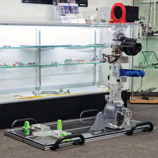
Pioneer Circuits tested
its latest flexible circuitry
on this mock-up of the
Mars 2020 rover’s mast.
NASA

                                                                  The copper clad in this
                                                                  image gives rigid flex
                                                                  circuits their flexibility.
                                                                                               Pioneer Circuits

                                                                  They are inside the
                                                                  cameras of the Mars
                                                                  2020 rover.

18     |   APRIL 201 8         |   aerospaceamerica . aiaa .org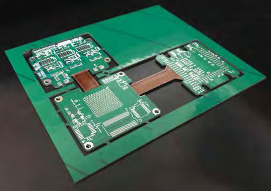
This image taken by the
                                                                                                                        Curiosity rover on the
                                                                                                                        Martian surface shows
                                                                                                                        the extended length flex
                                                                                                                        flight part (brown, flat
                                                                                                                        cable that starts on deck
                                                                                                                        and wraps around the
                                                                                                                        mast) that powers the
                                                                                                                        camera and the rest of
                                                                                                                        the rover.
                                                                                                                        NASA

                                                                                                                         Dale McKeeby           , vice
                                                                                                                         president of engineering at
                                                                                                                         Pioneer Circuits of Santa
                                                                                                                         Ana, California. He joined
                                                                                                                         the company in 1991 and
                                                                                                                         now leads research and
                                                                                                                         development, concurrent
                                                                                                                         engineering, and prototype
                                                                                                                         manufacturing for the Deep
                                                                                                                         Space sector. Pioneer’s other
here to our facilities, to make sure the upgrades to        would also have the highest reliability. I provided          business sectors are military
the flex circuit would work and be just as reliable          open communication with the JPL team, provid-                applications, satellites and
for the Mars 2020 rover.                                    ing weekly updates and sharing challenges of the             avionics. Email
    Also, the electronics inside these cameras utilize      different configurations along the way. JPL then              info@pioneercircuits.com
rigid flex circuits, which combine the durability           pulled up original design drawings from previous
of rigid circuits with the reliability and flexibility of    rovers and worked with us to update it for the new
flex circuits. The main objectives of using flex and          configuration.
rigid flex circuits was to overcome space and weight             The rover’s human-like arm will have a Force
confinements as well as to improve reliability as we         Torque Sensor to detect the forces applied to the
did for the original Mars Pathfinder Sojourner rover.        arm to give the robot feedback and help it be flexible
Back during development of the other rovers, I recall       and adaptable in its movements. Several companies
sitting in a NASA board meeting with JPL where              including JPL and Motiv Space Systems came to
different project managers were answering questions.        Pioneer for help with multilayer flex circuit man-
One key question was what percentage of hard wir-           ufacturing as well as the difficult final assembly.
ing on the rovers after Sojourner could be replaced         The arm’s newly developed, multilayer flexible
by flex circuits. The answer to this was 17 to 20 percent,   circuit package provides for finer torque control.
which satisfied the NASA question. This meeting             In fact, the Force Torque Sensor system is the most
laid a strong foundation and path forward for the           complex flex circuit assembly ever integrated into
JPL team and me to work on the rigid flex parts for          a Mars rover arm.
future rovers.                                                  Overall, Mars 2020 adds to the list of flexible
    For Mars 2020, we relied on mock-ups to develop         circuit technologies that power the capabilities of
the tightest and most robust configurations that             Mars rovers. +

                                                                           aerospaceamerica . aiaa .org             |     APRIL 201 8          |    19
You can also read