Framework for Autonomous Onboard Navigation with the AR.Drone
←
→
Page content transcription
If your browser does not render page correctly, please read the page content below
Framework for Autonomous Onboard
           Navigation with the AR.Drone
                                Jacobo Jiménez Lugo and Andreas Zell
                                Cognitive Systems, University of Tübingen
                                            Tübingen, Germany
                           Email: {jacobo.jimenez,andreas.zell}@uni-tuebingen.de

   Abstract—We present a framework for autonomous         for example, the Stanford’s STARMAC quadrotor
flying using the AR.Drone low cost quadrotor. The         testbed [4] created for multi agent experimentation
system performs all sensing and computations on-          or the pixhawk project from ETH Zurich [5] de-
board, making the system independent of any base
station or remote control. High level navigation and      signed for on-board computer vision, which features
control tasks are carried out in a microcontroller that   a single board computer with a multi-core pro-
steers the vehicle to a desired location. We experimen-   cessor. Using an already available flight controller
tally demonstrate the properties and capabilities of      boards can speed up the process of building a
the system autonomously following several trajectory      quadrotor. Lim et al. [6] provide an overview of
patterns of different complexity levels and evaluate
the performance of our system.                            the characteristics of many open source platforms.
                                                             However, building a platform can be expensive
                    I. I NTRODUCTION                      and requires time and knowledge to design a flight
   The popularity of the research on micro un-            controller. Low cost solutions are favored in sce-
manned aerial vehicles has increased in the recent        narios with a high risk of losing the vehicle. For
years. Quadrotors are a very popular choice among         example, Tayebi et al. [7] exploited low cost gyro-
MAV platforms due to their robustness, mechan-            scopes for attitude estimation. Low cost sensors can
ical simplicity, low weight and small size. Their         be used for autonomous navigation of quadrotors.
agility and maneuverability have been demonstrated        The infrared camera of the Nintendo Wii remote
through triple flips [1], ball juggling [2] and ag-       controller was used for autonomous take off and
gressive maneuvering through windows [3]. These           landing on a moving ground vehicle [8] and for fol-
characteristics make the quadrotor an ideal platform      lowing another quadrotor [9]. The camera tracked
for operations such as exploration, surveillance,         active markers on the targets to estimate the relative
search and rescue or even artistic performances.          position of the quadrotor.
   Several quadrotor platforms are available for the         In 2010, the french company Parrot launched the
research community. Commercial quadrotors from            AR.Drone, a $300 quadrotor that was developed
companies like Ascending Technologies1 or Mi-             for the mass market of video games. It quickly
crodrones2 are among the most frequently used in          attracted the attention of the research community
research due to their robustness, though they are         with features such as on-board cameras and stable
expensive and the firmware is not always customiz-        hovering. The AR.Drone has become a popular plat-
able. The other option for researchers is to develop      form for research and education. It has been used
their own platforms according to the application’s        for object following, position stabilization and au-
needs. This idea was exploited in several projects,       tonomous navigation [10]. Faigl et al. [11] used the
                                                          AR.Drone for surveillance. The AR.Drone’s camera
  1 www.asctec.de                                         was used to learn a feature map of a determined
  2 www.microdrones.com                                   area. In subsequent flights the feature map was used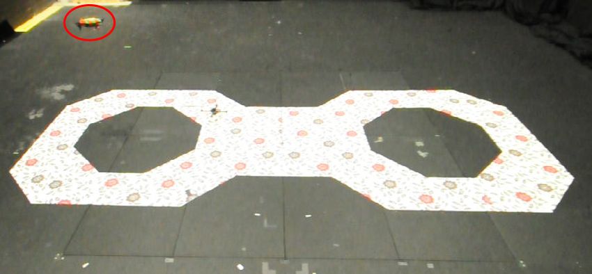
together with the AR.Drone’s odometry to navigate
through the area. Bills et al. [12] classified indoor
environments based on images from the AR.Drone.
They used visual cues inherent in the environment
to fly through it. Engel et al. [13] demonstrated
figure flying using images from the AR.Drone as an
input for the parallel tracking and mapping (PTAM)
algorithm [14]. The output of PTAM was fused
with the vehicle’s inertial measurement unit (IMU)
data to produce a more accurate position estimate.
The mentioned AR.Drone applications depend on
a base station that extracts relevant information for
path planning, navigation, control algorithms and
generate a steering command. The base station com-
municates with the AR.Drone through a wireless
network, which limits the working distance of the       Fig. 1: Low cost quadrotor AR.Drone version 1.0
system and introduces a delay in the information        and 8-bit microcontroller. The AR.Drone used for
exchange of sensor data and control commands.           trajectory following experiments. The microcon-
   The motivation behind this work is to extend         troller is in charge of path planning and control
the AR.Drone to enable autonomous flight and            tasks.
show that figure flying is possible with a low-cost
system just over $300. The system does not need
a base station, relying only on on-board sensing        (see Figure 1). The central cross of the AR.Drone
and processing, thus minimizing the communication       is made of carbon fiber tubes joined by a central
delays.                                                 plastic plate. A brushless motor is mounted at the
   We present a framework for autonomous nav-           end of each arm. The electronics are housed by
igation of the AR.Drone with minimal hardware           a plastic basket on the center of the cross and an
and software additions. The framework can be            Expanded Poly Propylene body.
easily customized or upgraded. We implemented           The electronic hardware comprises two boards con-
high level control and trajectory planning tasks for    nected to each other and attached to the plastic
autonomous figure flying. We evaluated our system       basket in the center of the cross to reduce vibrations.
in a series of indoor experiments.                      One board, the motherboard, contains the main
   The remainder of the paper is as follows. We pro-
                                                        processing unit (an ARM9 processor running at
vide an overview of the AR.Drone’s hardware and
                                                        468 MHz on AR.Drone 1.0 and an ARM Cortex-A8
software including vision and control algorithms in
                                                        at 1 GHz on AR.Drone 2.0), two cameras, a Wi-Fi
section II. We describe our system’s architecture
                                                        module and a connector for software flashing and
in section III. We present the evaluation results in
                                                        debugging. The cameras have different orientations.
section IV and conclude the paper in section V.
                                                        One is oriented vertically, pointing to the ground.
            II. AR.D RONE P LATFORM                     It has an opening angle of 63 ◦ , a frame rate of
  This section provides a brief overview of the         60 frames per second (fps) and a a resolution of
AR.Drone quadrotor. A more complete description         320 × 240 pixels. This camera is used to estimate
of the algorithms can be found in [15].                 the horizontal speed of the vehicle. The second
                                                        camera is pointing forwards. It has an opening angle
A. Hardware                                             of 93 ◦ , a frame rate of 15 fps and a resolution of
   The AR.Drone is a quadrotor with a size of 55 cm     640 × 480 pixels on version 1.0. Version 2.0 has
rotor-tip to rotor-tip and 380-420 grams of weight      an improved front camera that can deliver high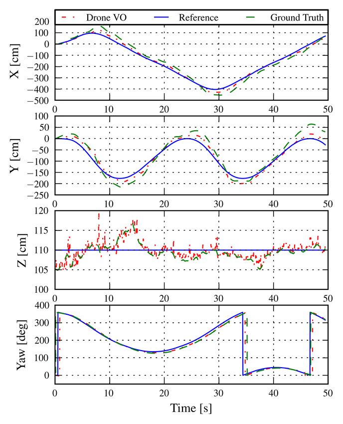
definition images at 720p resolution at 30 fps . Both    To achieve a stable hovering and position control,
cameras can be used for detection of markers such        the AR.Drone estimates its horizontal velocity us-
as stickers, caps or hulls of other AR.Drones.           ing its vertical camera. Two different algorithms
The second board, the navigation board, contains         are used to estimate the horizontal velocity. One
all the sensors necessary for the state estimation       tracks local interest points (FAST corners [16])
of the quadrotor. The sensor suite includes a low        over different frames and calculates the velocity
cost inertial measurement unit (IMU) that updates        from the displacement of these points. It provides
the state of the AR.Drone at 200 Hz. The IMU             a more accurate estimate of the velocity and is
consists of a 3-axis accelerometer, 2-axis gyroscope     used when the vehicle’s speed is low and there is
to measure angular velocities on pitch and roll          enough texture in the picture. The second algorithm
axes and a more precise gyroscope to measure the         estimates the horizontal speed by computing the
angular velocity on the yaw axis. The distance to        optical flow on pyramidal images. It is the default
the ground is measured by an ultrasonic sensor with      algorithm during flight. It is less precise but more
a maximum range of 6 m. The AR.Drone version             robust since it does not rely on highly textured or
2.0 also equips a barometric sensor to measure its       high-contrast scenes.
height beyond the range of the ultrasonic sensor.           The AR.Drone uses inertial information from its
This measurement is also used to determine the           IMU for estimating the state of the vehicle. It fuses
scene depth in the images of the vertical camera and     the IMU data with information from the vision
to calculate vertical displacement of the vehicle.       algorithms and an aerodynamics model to estimate
                                                         the velocity of the vehicle.
B. Software                                                 2) Control: The control of the AR.Drone is
   The AR.Drone can be remote controlled via a           performed in a nested fashion. The innermost loop
smartphone or a tablet PC. It can also accept            controls the attitude of the vehicle using a PID
commands or send data to a PC via an AR.Drone            controller to compute a desired angular rate based
API. The drone can send two types of data streams:       on the difference between the current estimate of
a navdata stream that contains data related to the       the attitude and the attitude set point defined by the
state of the vehicle and a video stream that provides    user controls. The second loop uses a proportional
encoded video from the cameras. The navigation           controller to drive the motors.
data includes the status of the vehicle, motors and         When the controls are released, the AR.Drone
communications as well as raw and filtered IMU           computes a trajectory that will take it to zero
measurements, attitude (roll, pitch, yaw), altitude,     velocity and zero attitude in a short time. This
linear velocities and an position with respect to take   technique is designed off-line and uses feed-forward
off point computed from visual information. The          control over the inverted dynamics of the quadrotor.
navigation data also includes information from the
detection of visual tags. The received video can                   III. S YSTEM A RCHITECTURE
be from either of the two cameras or a picture-             Our system consists of two main components: a
in-picture video with one of the camera images           microcontroller and a proxy program that serves as
superposed on the top left corner of the other one.      a bridge between the AR.Drone and the microcon-
   The ARM processor runs an embedded Linux              troller (Figure 2). The microcontroller we used is
operating system that simultaneously manages the         an ATMEL ATmega 1284 8-bit microcontroller. It
wireless communications, visual-inertial state esti-     runs at 14.7456 Mhz, has 128 Kb of memory, 32 I/O
mation and control algorithms.                           pins, counters and timers with PWM capabilities
   1) Navigation Algorithms: The AR.Drone pro-           as well as two USART ports and a 10-bit analog
vides sophisticated navigation algorithms and as-        to digital converter. It extends the capabilities of
sistance in maneuvers such as take off, landing          the AR.Drone to enable autonomous flying with-
and hovering-in-position to ensure user’s safety.        out the need of a ground station or any remote
AR. Drone listens on the navigation port for incoming data,
sorts the data, packs it into a binary message and
sends it to the microcontroller. At the same time
Proxy: it listens for AR.Drone’s configuration or control
-Get navigation data commands coming from the microcontroller. These
-Redirect control commands
commands are directly forwarded to the AR.Drone’s
command port.
Serial
2) Microcontroller: To execute autonomous nav-
igation and control algorithms on board, we at-
tached the microcontroller to the debugging port of
Microcontroller:
-Sensor processing the AR.Drone. With these algorithms running on the
-Path planning microcontroller all the computational resources on
-Control
the AR.Drone are reserved for its pose estimation
Serial and control algorithms.The microcontroller allows
Serial, I2C... Xbee
us to interface with a wide variety of sensors for
Sensors: Optional Base Station:
-Range -Path selection example, ultrasonic or infrared range sensors, GPS,
-Temperature -Parameter config temperature sensors or radio communications. The
-GPS -Logging
number of sensors that can be added is limited
by the microcontroller’s specifications, their power
Fig. 2: System software components. The proxy consumption and the payload of the AR.Drone.
application runs on the AR.Drone and enables ex-
The additional hardware weights approximately
change of information with the microcontroller. The
25 g. With the weight located at the center of
microcontroller plans a trajectory using the position
the AR.Drone, there is no noticeable influence on
estimation of the AR.Drone and computes control
flight performance with the outdoor protective hull
commands for the vehicle. The microcontroller can
and a 10 cm height loss on the hovering after the
interface with different. An optional base station
take off which the controllers are able to correct.
communicates with the microcontroller to configure
With our current setup, flight time is reduced by
the flight and log flight data.
approximately 2-3 minutes due to the extra weight
and power consumption of the microcontroller.
The software framework for autonomous fig-
control device, thus widening its application range ure flying runs on this microcontroller. It consists
and eliminating delays that may be caused by the of three modules: position estimation, path plan-
communication with the base. The microcontroller ning and control. The first module exploits the
(Figure 1) is fitted inside the hull and plugged into AR.Drone’s position estimates from vision algo-
the serial (debugging) port on the motherboard. rithms (see section II). The position and heading
1) AR.Drone Proxy: We uploaded an external are provided in world coordinates with the origin
application to the AR.Drone to exchange infor- at the take off location and the height value as the
mation with the microcontroller, i.e. send steering current measurement over the ground. The proxy
commands, retrieve its status, sensor measurements, application gets these data from the AR.Drone’s
attitude and pose estimates. The microcontroller navigation data stream. Then the proxy applica-
starts the application after the AR.Drone finishes tion builds a binary message with the AR.Drone’s
its booting sequence. The application connects to status, its position and heading and sends it to
the navigation and command ports of the AR.Drone the microcontroller. We treat the AR.Drone as an
main program and requests the navigation data additional sensor providing position information to
(velocities, altitude, orientation and position from the planning and control modules running on the
take off point). The application acts as a proxy: It microcontroller.The second module, path planning, computes a
trajectory for the AR.Drone to follow, based on
predefined shapes or user defined waypoints. To
follow a predefined shape, which can be a simple
straight line, a circle or an eight shape, we calcu-
lated mathematical equations that parametrize the
shape according to its size. To follow waypoints,
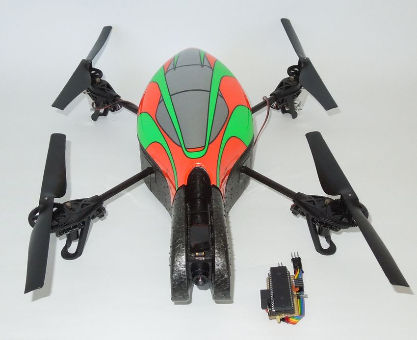
we define a series of coordinates that outline a Fig. 3: Indoor environment for the path planning
desired trajectory. Each waypoint w is defined as experiments. The room is equipped with a motion
a triplet w = [x, y, z] where x, y, z are in world capture system to provide positioning ground truth.
coordinates with the origin as the take off location The figure of eight is marked on the floor to provide
of the vehicle. The trajectory is computed as a series texture for the AR.Drone’s vision algorithms.
of smooth connected functions of time for each of
the axes. The individual functions have the form
at + bt2 + ct3 where the coefficients a, b and c are IV. E XPERIMENTS AND R ESULTS
computed before the flight using the desired veloc- A. Experimental setup
ity of the vehicle. The yaw angle φ is computed To test the capabilities of our system and an-
so that the front camera of the AR.Drone points in alyze its performance, we performed a series of
the direction of the next waypoint. Navigating in autonomous flights. We used an AR.Drone version
this way keeps the camera pointing always in the 1.0 communicating with the microcontroller as de-
direction of flight but is not optimal for the control scribed in section III. Flight data are logged at
of quadrotors. Yaw rotation produces centrifugal a frequency of approximately 30 Hz on the base
forces that push the vehicle away from the desired station that communicates with the microcontroller
path requiring additional maneuvering to correct its using a radio module. The flight experiments were
trajectory. performed in two different rooms, both equipped
with a motion capture system that monitors the
position of the vehicle at a frequency of 100 Hz
In the third module, trajectory following control, with millimeter precision for accurate ground truth
we feed the AR.Drone’s position estimate and the measurements. One environment was a small room
planned set point position to four PID controllers. where the motion capture system covers a volume
The PID controllers compute commands for the roll, of 3 × 3 × 2 m3 . The room has a carpet that pro-
pitch and yaw angles and for the desired height of vides texture for the estimation algorithms of the
the vehicle independently from each other. These AR.Drone. The second room covers a larger volume
commands are then sent back to the AR.Drone via of 10 × 12 × 6 m3 . This room lacks texture on the
the proxy application that redirects it to the vehicle’s floor so we laid colored paper on the floor forming
command port. The control gains for each controller the figure of an eight to provide the texture (see
were experimentally determined. Figure 3).
To test the trajectory following, we defined way-
points within a 2 × 2 m2 area of the small room
Path planning and PID controller parameters can arranged to form different patterns. After loading
be configured from an optional base station. The parameters for the flight to the microcontroller, it
base station communicates with the microcontroller calculated the trajectory to follow. We then com-
on the AR.Drone via a radio module. It records manded the AR.Drone to hover at 1.10 m height
flight data and displays useful information from and then start the autonomous flight. The AR.Drone
the vehicle like its status and battery level and a flew three figures with varying level of difficulty: a
visualization of the path. square, a zig-zag and a spiral. In the larger room,TABLE I: Error analysis of AR.Drone’s odometry
Short trajectory
x [cm] y [cm] z [cm] yaw [deg.]
RMSE 4.88 3.14 0.69 3.05
Std. Dev. 2.77 3.01 0.78 1.50
Max Error 11.81 10.32 6.74 6.40
Long trajectory
x [cm] y [cm] z [cm] yaw [deg.]
RMSE 8.04 12.82 1.21 9.20
Std. Dev. 6.04 11.57 1.18 5.80
Max Error 25.26 40.60 10.28 17.74
TABLE II: Error analysis of trajectory tracking
Short trajectory
x [cm] y [cm] z [cm] yaw [deg.]
RMSE 7.55 12.02 3.06 4.02
Std. Dev. 7.23 7.28 2.74 2.82
Max Error 25.7 29.7 11.30 13.90
Long trajectory
x [cm] y [cm] z [cm] yaw [deg.]
RMSE 7.58 11.34 3.14 5.93
Std. Dev. 4.91 6.90 2.04 3.34
Max Error 23.20 26.00 12.50 14.51
data and interpolating the tracking system’s data at
Fig. 4: Measurements from a typical trajectory the time marked by the AR.Drone’s data log times-
following experiment. The AR.Drone was com- tamp. We measured the accuracy of the AR.Drone
manded to follow an eight shape trajectory of size pose estimation by comparing it with ground truth
5 m × 1.75 m at an altitude of 1.10 m. Planned path data (see Table I). The root mean square error on
(solid blue), AR.Drone’s estimated position (dash- the short trajectories was smaller than 5 cm and
dotted red) and the ground truth (dashed green) are on the longer trajectory around 10 cm on x and y
shown. Note that the yaw angle trajectory is smooth axes while on the yaw angle the RMSE was around
and the plot shows the wraparound at 360 ◦ . 3 ◦ and 10 ◦ , respectively. The difference in error
values can be caused by drift in the sensors, which
translates to a small drift of the position estimation.
the AR.Drone was commanded to fly a predefined As it was expected, the height estimation from the
figure-eight of 5 m length and 1.75 m width over ultrasonic range sensor yields comparable results
the marked figure on the floor of the room while in both experiments (around 1 cm). The errors and
keeping a constant height of 1.10 m. standard deviations in all axes showed that the
AR.Drone’s odometry provides enough accuracy for
B. Results flying figures autonomously.
To evaluate the performance of our system, we Figure 4 shows the measurements of the position
analyzed the data collected from 20 flights. We first and heading of the vehicle during a typical flight
synchronized the data logged on the base station of the figure eight. A top view of one of the
with the data provided by the tracking system. The experiments where we flew the figure eight is shown
data from both systems is synchronized by noting in Figure 5. Figure 6 shows the top view of the
the start of the experiment (movement along x-y spiral, zig-zag and square figures flown in the small
axis) on both data logs, the end of the AR.Drone’s room.
log and the total time of the experiment from these We analyzed the performance of the controllers(a) spiral (b) ZigZag
(c) Square
Fig. 6: X-Y projections of typical flights of the spiral, zig-zag and square figures flown in the small room.
The different trajectories were computed from waypoints defined in the 3 × 3 × 2 m3 volume of the room.
for trajectory following by comparing the planned V. C ONCLUSION
trajectory with the pose estimate of the AR.Drone
(see Table II). The controllers performed very sim- We presented a framework that allows the low-
ilar on both short and long trajectories as suggested cost quadrotor AR.Drone to perform autonomous
by the RMSE and standard deviation values on all flights. Our method uses on board sensing only,
axes. There was a slightly larger error and standard and all the computations performed are on board as
deviation on the shorter flights, since the trajectories well. The system can be used for extended distances
involved more changes in the heading direction of since it does not require any base station or remote
the vehicle than in the larger figure-eight, and in the control to operate. It can be easily customized and
case of the spiral, the changes were increasingly extended with additional sensors or a more powerful
faster. With these properties, our controllers are microcontroller that can speed up the computa-
capable of autonomous operation of the AR.Drone tions or carry out more computationally challenging
in reduced and narrow spaces with average errors tasks.
5 times smaller than the size of the vehicle and We evaluated the system capabilities by follow-
maximum errors of about half a vehicle length. ing predefined trajectories and a series of usertheir tracking system room and Karl E. Wenzel for
his valuable input and advice with the AR.Drone.
R EFERENCES
[1] S. Lupashin, A. Schöllig, M. Sherback, and R. D’Andrea,
“A simple learning strategy for high-speed quadrocopter
multi-flips,” IEEE International Conference on Robotics
and Automation, pp. 1642–1648, 2010.
[2] M. Muller, S. Lupashin, and R. D’Andrea, “Quadrocopter
ball juggling,” IEEE/RSJ International Conference on In-
telligent Robots and Systems, pp. 5113–5120, 2011.
[3] D. Mellinger, N. Michael, and V. Kumar, “Trajectory gen-
eration and control for precise aggressive manuevers with
quadrotors,” International Journal of Robotics Research,
2012.
Fig. 5: X-Y projection of a typical eight shape [4] G. Hoffmann, D. Rajnarayan, S. Waslander, D. Dostal,
J. Jang, and C. Tomlin, “The stanford testbed of au-
trajectory flight In our experiments in the large tonomous rotorcraft for multi agent control (starmac),” in
room the AR.Drone followed an eight shape tra- Digital Avionics Systems Conference, 2004. DASC 04. The
jectory at a constant height of 1.10 m. The stating 23rd, vol. 2. IEEE, 2004, pp. 12–E.
[5] L. Meier, P. Tanskanen, F. Fraundorfer, and M. Polle-
point is chosen so the AR.Drone starts with a yaw feys, “Pixhawk: A system for autonomous flight using
angle of 0 ◦ . Planned path (solid blue), AR.Drone’s onboard computer vision,” IEEE International Conference
estimated position (dash-dotted red) and the ground on Robotics and Automation (ICRA), 2011., pp. 2992 –
2997, may 2011.
truth (dashed green) are shown.
[6] H. Lim, J. Park, D. Lee, and H. J. Kim, “Build your
own quadrotor: Open-source projects on unmanned aerial
vehicles,” IEEE Robot. Automat. Mag., vol. 19, no. 3, pp.
33–45, 2012.
defined waypoints. We used the AR.Drone’s visual [7] A. Tayebi, S. McGilvray, A. Roberts, and M. Moallem,
odometry which provided reliable estimates for this “Attitude estimation and stabilization of a rigid body using
task. The trajectory tracking errors were small in low-cost sensors,” 46th IEEE Conference on Decision and
Control, 2007., pp. 6424 –6429, dec. 2007.
comparison with the size of the quadrotor. This [8] K. Wenzel, A. Masselli, and A. Zell, “Automatic take off,
shows that our system is capable of flying in narrow tracking and landing of a miniature uav on a moving carrier
environments. vehicle,” Journal of Intelligent & Robotic Systems, vol. 61,
pp. 221–238, 2011, 10.1007/s10846-010-9473-0.
We found that sometimes the visual odometry [9] K. E. Wenzel, A. Masselli, and A. Zell, “Visual tracking
of the AR.Drone delivers position estimates with and following of a quadrocopter by another quadrocopter,”
a very high error leading ultimately to a large IEEE/RSJ International Conference on Intelligent Robots
and Systems (IROS 2012), pp. 1–6, October 7-12 2012,
deviation from the planned trajectory without the accepted for publication.
system being able to correct it. The problem was [10] M. Saska, T. Krajnı́k, J. Faigl, V. Vonásek, and L. Preucil,
solved after resetting the AR.Drone. Another re- “Low cost mav platform ar-drone in experimental verifi-
striction is the limited computational power of the cations of methods for vision based autonomous naviga-
tion,” in IEEE/RSJ International Conference on Intelligent
microcontroller which is insufficient to process the Robots and Systems (IROS 2012), 2012, pp. 4808–4809.
images of the on board cameras. This will be [11] J. Faigl, T. Krajnı́k, V. Vonásek, and L. Přeučil,
solved in the future by mounting a more powerful, “Surveillance planning with localization uncertainty for
uavs,” pp. –, 2010. [Online]. Available: http://www.
lightweight single board computer. icr2010.org.il/
[12] C. Bills, J. Chen, and A. Saxena, “Autonomous mav flight
ACKNOWLEDGMENT in indoor environments using single image perspective
cues,” IEEE International Conference on Robotics and
The authors would like to thank Volker Grabe and Automation, pp. 5776 –5783, may 2011.
[13] J. Engel, J. Sturm, and D. Cremers, “Camera-based naviga-
Dr. Paolo Robuffo Giordano from the Max Planck tion of a low-cost quadrocopter,” Proc. of the International
Institute of Biological Cybernetics for letting us use Conference on Intelligent Robot Systems (IROS), Oct. 2012.[14] G. Klein and D. Murray, “Parallel tracking and mapping uav,” in 18th IFAC World Congress, Milano, Italy, 2011, pp.
for small AR workspaces,” in Proc. Sixth IEEE and ACM 1477–1484.
International Symposium on Mixed and Augmented Reality [16] M. Trajkovic and M. Hedley, “Fast corner detection,”
(ISMAR’07), Nara, Japan, November 2007. Image and Vision Computing, vol. 16, no. 2, pp. 75 – 87,
1998.
[15] P.-J. Bristeau, F. Callou, D. Vissiere, and N. Petit, “The
navigation and control technology inside the ar.drone microYou can also read