WGM-201 Waveform Generator Manual - Syscomp Electronic Design Limited Version 1.08
←
→
Page content transcription
If your browser does not render page correctly, please read the page content below
WGM-201
Waveform Generator Manual

  http:\\www.syscompdesign.com
           Version 1.08
          September 3, 2012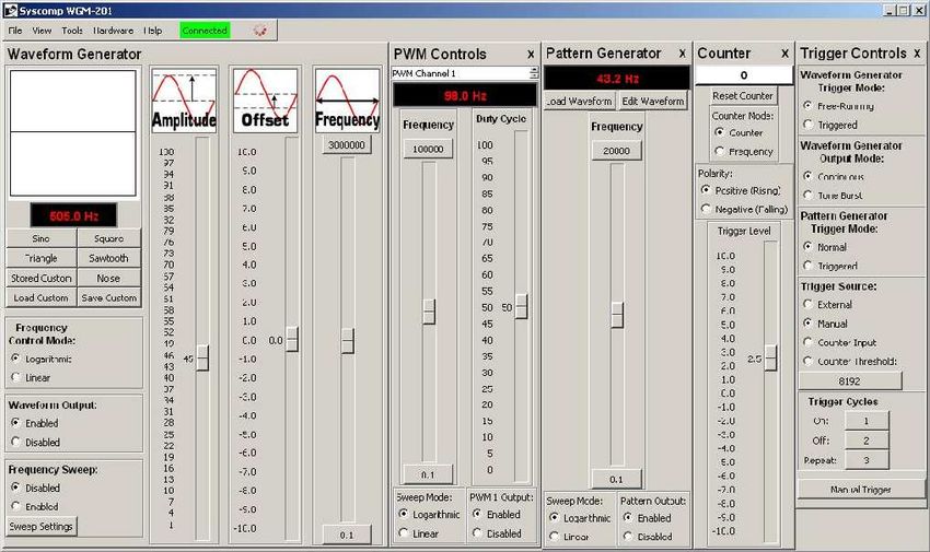
Revision History
    Version    Date        Notes
     1.00     Oct 2009     First revision
     1.01     May 2010     Added section on arbitrary waveform
                           Added directions for waveform sync
     1.02     May 2010     Added command information
     1.03     Dec 2010     Added sweep modes
     1.04     Mar 2011     Added WaveMaker reference
                           Added Triggered Tone BurstExample
     1.05      Apr 2011    Added more command information
     1.06      Aug 2012    Corrected Enable/Disable command
     1.07      Sep 2012    Added terminal-emulator notes.
     1.08                  Added command example

Contents
1    Overview                                                                                                                                                                                   1
     1.1   Specification . . . . . . . .   .   .   .   .   .   .   .   .   .    .   .   .   .   .   .   .   .   .   .   .   .   .   .   .   .   .   .   .   .   .   .   .   .   .   .   .   .   1
     1.2   Basic Operation . . . . . .     .   .   .   .   .   .   .   .   .    .   .   .   .   .   .   .   .   .   .   .   .   .   .   .   .   .   .   .   .   .   .   .   .   .   .   .   .   2
     1.3   Graphical User Interface .      .   .   .   .   .   .   .   .   .    .   .   .   .   .   .   .   .   .   .   .   .   .   .   .   .   .   .   .   .   .   .   .   .   .   .   .   .   2
     1.4   Selecting Waveform . . . .      .   .   .   .   .   .   .   .   .    .   .   .   .   .   .   .   .   .   .   .   .   .   .   .   .   .   .   .   .   .   .   .   .   .   .   .   .   3
     1.5   Manual Frequency Setting        .   .   .   .   .   .   .   .   .    .   .   .   .   .   .   .   .   .   .   .   .   .   .   .   .   .   .   .   .   .   .   .   .   .   .   .   .   3

2    Frequency Sweep                                                                                                                                                                            3
     2.1   Manual sweep . . . . . . . .        .   .   .   .   .   .   .   .    .   .   .   .   .   .   .   .   .   .   .   .   .   .   .   .   .   .   .   .   .   .   .   .   .   .   .   .   4
     2.2   Automatic Sweep . . . . . .         .   .   .   .   .   .   .   .    .   .   .   .   .   .   .   .   .   .   .   .   .   .   .   .   .   .   .   .   .   .   .   .   .   .   .   .   4
         2.2.1 Continuous Sweep . .            .   .   .   .   .   .   .   .    .   .   .   .   .   .   .   .   .   .   .   .   .   .   .   .   .   .   .   .   .   .   .   .   .   .   .   .   6
         2.2.2 Sweep Trigger Output            .   .   .   .   .   .   .   .    .   .   .   .   .   .   .   .   .   .   .   .   .   .   .   .   .   .   .   .   .   .   .   .   .   .   .   .   6
         2.2.3 Sweep Trigger Input .           .   .   .   .   .   .   .   .    .   .   .   .   .   .   .   .   .   .   .   .   .   .   .   .   .   .   .   .   .   .   .   .   .   .   .   .   6

3    Tone Burst                                                                                                                                                                                 6
     3.1   Triggered Tone Burst . . . . . . . . . . . . . . . . . . . . . . . . . . . . . . . . . . . . . . . .                                                                                 7

4    Pulse Generator                                                                                                                                                                            8

5    Pattern Generator                                                                                             10
     5.1    Creating a Digital Pattern . . . . . . . . . . . . . . . . . . . . . . . . . . . . . . . . . . . . . . 10
     5.2    Pattern File Format . . . . . . . . . . . . . . . . . . . . . . . . . . . . . . . . . . . . . . . . . 12

6    Counter                                                                                                                                                                                    13

7    Arbitrary Waveform                                                                                                                                                                         13
     7.1   Low and High Frequency Settings . . . . . . . . . . . . . . . . . . . . . . . . . . . . . . . . .                                                                                    13
     7.2   Detail in Arbitrary Waveforms . . . . . . . . . . . . . . . . . . . . . . . . . . . . . . . . . . .                                                                                  14
     7.3   Waveform Editor . . . . . . . . . . . . . . . . . . . . . . . . . . . . . . . . . . . . . . . . . .                                                                                  14

8    Synchronizing Two Generators                                                                                                                                                               14

9    Commands                                                                                                                                                                                   15
     9.1 Setting up the Terminal: Overview . . . . . . . . . . . . . . . . . . . . . . . . . . . . . . . . .                                                                                    15
     9.2 Terminal Emulator under Windows . . . . . . . . . . . . . . . . . . . . . . . . . . . . . . . . .                                                                                      15
     9.3 Command Listing . . . . . . . . . . . . . . . . . . . . . . . . . . . . . . . . . . . . . . . . . .                                                                                    16

                                                                               ii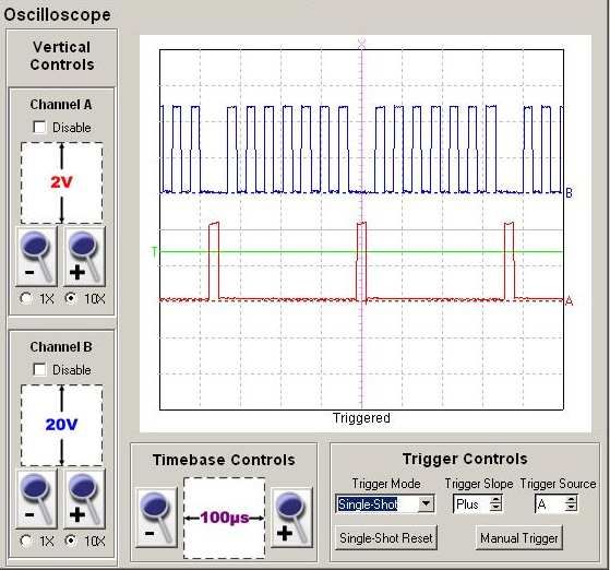
10 Rear Panel Connector                                                                                    21
   10.1 Rear Panel Connector Mating Plug . . . . . . . . . . . . . . . . . . . . . . . . . . . . . . . . . 21

11 Creating an Arbitrary Waveform                                                                                                                                                 22

List of Figures
   1     WGM-201 Graphical User Interface . .         .   .   .   .   .   .   .   .   .   .   .   .   .   .   .   .   .   .   .   .   .   .   .   .   .   .   .   .   .   .   .    3
   2     Minimum User Interface . . . . . . . .       .   .   .   .   .   .   .   .   .   .   .   .   .   .   .   .   .   .   .   .   .   .   .   .   .   .   .   .   .   .   .    4
   3     Sweep Mode Control Panel . . . . . . .       .   .   .   .   .   .   .   .   .   .   .   .   .   .   .   .   .   .   .   .   .   .   .   .   .   .   .   .   .   .   .    4
   4     Trigger Controls Panel . . . . . . . . .     .   .   .   .   .   .   .   .   .   .   .   .   .   .   .   .   .   .   .   .   .   .   .   .   .   .   .   .   .   .   .    6
   5     Tone Burst Oscilloscope Display . . . .      .   .   .   .   .   .   .   .   .   .   .   .   .   .   .   .   .   .   .   .   .   .   .   .   .   .   .   .   .   .   .    7
   6     Pulse Generator Control Panel . . . . .      .   .   .   .   .   .   .   .   .   .   .   .   .   .   .   .   .   .   .   .   .   .   .   .   .   .   .   .   .   .   .    8
   7     Pattern Generator Control Panel . . . .      .   .   .   .   .   .   .   .   .   .   .   .   .   .   .   .   .   .   .   .   .   .   .   .   .   .   .   .   .   .   .   10
   8     Pattern Editor . . . . . . . . . . . . . .   .   .   .   .   .   .   .   .   .   .   .   .   .   .   .   .   .   .   .   .   .   .   .   .   .   .   .   .   .   .   .   11
   9     Pattern Demonstration . . . . . . . . .      .   .   .   .   .   .   .   .   .   .   .   .   .   .   .   .   .   .   .   .   .   .   .   .   .   .   .   .   .   .   .   11
   10    Counter Panel . . . . . . . . . . . . . .    .   .   .   .   .   .   .   .   .   .   .   .   .   .   .   .   .   .   .   .   .   .   .   .   .   .   .   .   .   .   .   13
   11    Synchronized Waveforms . . . . . . . .       .   .   .   .   .   .   .   .   .   .   .   .   .   .   .   .   .   .   .   .   .   .   .   .   .   .   .   .   .   .   .   14
   12    WGM-201 Rear Panel Connector Pinout          .   .   .   .   .   .   .   .   .   .   .   .   .   .   .   .   .   .   .   .   .   .   .   .   .   .   .   .   .   .   .   21

                                                              iii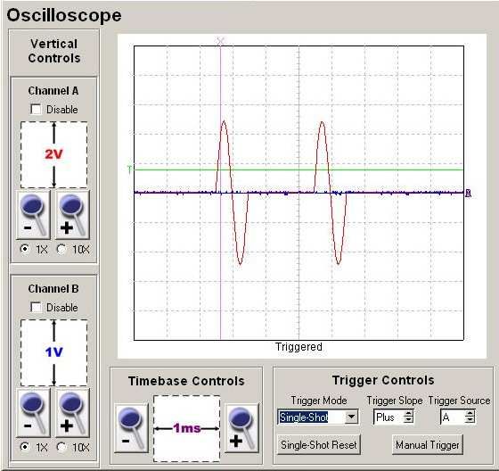
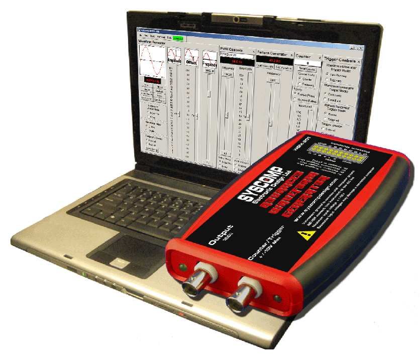
1 Overview
The Syscomp WGM-201 Waveform Generator is a general-purpose waveform generator, 8 bit digital word gen-
erator and general purpose counter. With many advanced features, it is useful for the teaching, development and
debugging of electronic circuits.
     The WGM-201 is one of a series of instruments from Syscomp Electronic Design. All instruments use a
computer host for the graphical user interface (GUI) control panel, and connect with the hardware via a USB
virtual COM port. The software is Open Source and runs under Windows, Linux and Mac operating systems.
The generator hardware receives power from the host PC via the USB connection so that no other power source
is required.
     The generator hardware is capable of producing a variety of waveforms. Sine, square, triangle and ramp (saw-
tooth) waveforms are installed in the firmware. In addition, an arbitrary waveform can be created and downloaded
into the generator. The generator can produce these waveforms at frequencies between 0.1Hz and 10MHz with
variable amplitude and variable DC offset.
     The waveform frequency is derived from a crystal oscillator, so it is precise and stable. The waveform ampli-
tude is determined by digital-analog conversion of digital values. The amplitude stability is determined by internal
voltage reference source and 1% resistor values.
     A PC host displays a graphical user interface for the function generator with frequency readouts, sliders,
clickable buttons and various other controls. The PC connects to the function generator hardware via a USB cable
so that no other power source is required.
     A Graphical User Interface (the GUI) program for operating the waveform generator is provided on the ac-
companying CDROM. The program is written in the Tcl/Tk language. It is completely Open Source, so it may be
modified and distributed freely.
     The USB interface emulates a serial port so that it may be accessed as a serial port device from a host computer.
Any language that can talk to a serial port can send commands to and receive data from the hardware unit.

1.1 Specification
The core waveform generator is uses Direct Digital Synthesis to create standard and arbitrary waveforms with
accuracy based on a crystal oscillator. Amplitude and offset are controlled by DAC hardware independent of the
core waveform generator, so that the waveform vertical resolution remains at 256 points regardless of amplitude
or offset.
    The waveform can be adjusted in frequency in steps of 0.03Hz (more precisely, 0.031247735Hz) over a total
range of 0.1Hz to 10MHz (sine) or 3MHz (all other waveforms).
    The default upper limit is shown as 3MHz. This may be changed by the operator. Recommended maximum
for a sine wave is 10MHz. Recommended maximum for other waveforms (square, ramp, triangle) is 3MHz.An
arbitrary waveform may contain spectral content up to a maximum of 10MHz. Maximum and minimum frequency
can be set to any points within that range. For example, the range can be set as 20Hz to 20kHz for audio work.
The characteristic curve of the control may be set to logarithmic or linear.
    The frequency may be set to sweep manually or automatically between the two limit frequencies, with ad-
justable sweep rate and frequency increment.

                                                          1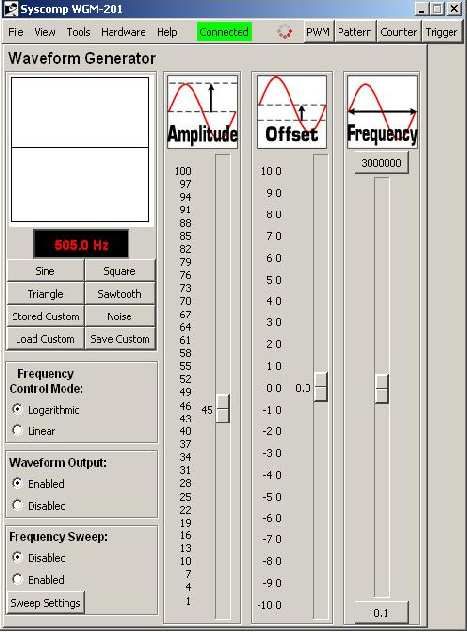
Core Waveform Generator
     Architecture                      Direct Digital Synthesis (DDS)
     Clock rate                        134MHz
     Waveform
     Vertical resolution               8 bits, independent of amplitude or offset
     Amplitude                         ±10Vp-p max, adjustable with 8 bit resolution
     Offset                            ±10V max, adjustable with 8 bit resolution
     Maximum output                    ±10V, signal plus offset
     Output impedance                  150 ohms
     Sine wave signal-Noise            >48db S/N, independent of output amplitude or offset
     Square wave rise and fall time    24nSec
     Waveform timebase                 256 points
     Types                             Sine, square, triangle, ramp, noise, arbitrary
     Arbitrary waveform                8 bit vertical by 256 time points
     Noise waveform                    Digital, 32 bit sequence generator, clock 134.208MHz
     Frequency
     Range, sine                       0.031Hz to 10MHz, resolution 0.1Hz
     Range, others:                    0.031Hz to 10MHz, resolution 0.1Hz
     Resolution                        0.031Hz
     Control                           Manual or automatic sweep
     Control curve                     Linear or Logarithmic characteristic
     Frequency limits                  Minimum and maximum frequencies are settable
     Frequency sweep
     Mode                              Linear or logarithmic characteristic
     Direction                         Initial direction up/down, start top/bottom frequency
     Sweep time step                   250mSec to 5000mSec per step
     Sweep step magnitude              User entered linear increment or log multiple
     Others
     Output                            Enable/disable
     Computer control                  All controls are remotely operated from the host PC

     Waveform Generator Trigger
     Mode                               Free-Running, Triggered
     Output                             Continuous, Tone Burst
     Source                             External, Manual, Counter input, Counter Threshold
     Cycles                             On, off, repeat

1.2 Basic Operation
In this section, we assume that the sofware has been installed successfully. The hardware is plugged into a USB
port and the GUI indicates Connected.
    On the hardware, the left (green) LED indicates POWER. The right is a dual LED, which flashes with each
command. When connected to the GUI, this LED lights more-or-less continuously.

1.3 Graphical User Interface
The full GUI is shown in figure 1. The main panel (the core generator) is on the left. There are four subsidiary
panels to the right, each with an X closer in the upper right corner. When the subsidiary panels are not being used,
they may be hidden to minimize screen space. Click on the X closer in the upper right corner to hide a panel. It is
replaced by a button on the main panel. Figure 2 shows all the subsidiary panels hidden. Notice the buttons in the
upper-right corner - they restore the subsidiary panels.

                                                         2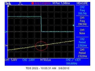
Figure 1: WGM-201 Graphical User Interface

1.4 Selecting Waveform
When powering up the WGM-201, the waveform is initially set to Sine. Other built-in waveforms are Square,
Triangle and Sawtooth.
   There are three buttons on the graphical user interface for controlling the custom waveform.
   Load Custom loads some arbitrary waveform into the generator waveform memory, and that waveform
now appears at the output of the generator. When you cycle the power, that waveform is lost.
   If you want to save the waveform so that it survives a power off-on cycle, use Load Custom to load the
waveform, and then Save Custom to write that waveform into permanent memory in the hardware.
   Thereafter, you can select that waveform by pressing the Stored Custom button. That waveform will
remain available unless you overwrite it with a new waveform.
   See section 7 on page 13 for more details on arbitrary waveform.

1.5 Manual Frequency Setting
There are three methods of setting the output frequency.
   1. Set the output frequency by moving the Frequency slider. The output frequency is shown in the frequency
      readout display, to the nearest 0.1Hz. The total frequency range of the frequency slider is established by the
      maximum and minimum frequencies shown at the top and bottom of the slider. Left-click on one of these
      to enter a new value.
   2. Move the frequency slider incrementally up or down with a left-click in the track area (the non-button area)
      of the frequency slider.
   3. Left-click on the frequency readout display. A data entry widget pops up. Type in the desired frequency.
      Left-click on OK.

2 Frequency Sweep
Frequency may be swept manually or automatically.

                                                         3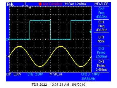
Figure 2: Minimum User Interface

2.1 Manual sweep
    • Click on the upper frequency limit (at the top of the frequency slider) and enter the maximum frequency of
      the sweep in Hertz, eg 20000.
    • Click on the lower frequency limit (at the bottom of the frequency slider) and enter the minimum frequency
      of the sweep in Hertz, eg 20.
    • Now drag the frequency slider between the bottom and the top limits. The frequency will sweep between
      20Hz and 20kHz as the slider is moved.

    The characteristic (Frequency Control Mode) of the frequency slider can be switched to Logarithmic or Linear.
    In linear mode, the frequencies between maximum and minimum are spread evenly over the range of the
slider. In the default state, this means that 3MHz is at the top of the slider, 1.5MHz at the mid point, and 300kHz
at 10% from the bottom. The bottom end of the scale is very compressed.
    In logarithmic mode, the frequencies are distributed like the keys on a piano. This is a more natural arrange-
ment for human hearing and means for example that each decade (frequency f to frequency 10f) occupies the
same linear space on the slider1 . Consequently, it’s much easier to use to set a given frequency.
    Logarithmic sweep mode has another advantage. Many response curves have linear segments when the ampli-
tude is measured in decibels (another logarithmic scale) and the frequency is a logarithmic scale. This simplifies
interpreting the result of a frequency sweep.

2.2 Automatic Sweep
The WGM-201 can automatically sweep the output frequency
over its entire frequency range or some part thereof.
    1 Signal generators of the past have used an approximation of the logarithmic control. There was a Range switch, which selected the

frequency in multiples of 10, and a Tune knob, which varied the frequency in a linear fashion over each range. The sweep was generally
limited to a range of 10:1. A few special-purpose instruments could sweep the audio band 20Hz to 20kHz, a range of 1000:1. The WGM-201
has a maximum sweep range of 107 : 1 and can also sweep over a very narrow range.

                                                                  4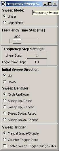
• Click on the upper frequency limit (at the top of the fre-
  quency slider) and enter the maximum frequency of the
  sweep in Hertz, eg 20000.
• Click on the lower frequency limit (at the bottom of the
  frequency slider) and enter the minimum frequency of the
  sweep in Hertz, eg 20.
• Click on the Sweep Settings button to open up the Fre-
  quency Sweep Settings control panel, figure 3.
• In the Frequency Sweep Settings control panel:
     – Select Linear or Logarithmic sweep. Logarithmic is
       most useful.
     – Select the Frequency Time Step using the slider. The
       generator produces a series of frequencies, stepping
       from one to the next. This control sets the time inter-
       val between frequency steps, ranging from 50mSec to
       5 seconds. A slower sweep is required for example
       when sweeping a device with a high-Q resonance.
     – Choose the Frequency Step Setting.
       For a linear sweep, click on the Linear Step button
       and enter the frequency increment between each out-
       put frequency. For example, if this is set to 10, then
       the frequency will increment by 10Hz with each new
       output.
       For a logarithmic sweep, click on the Logarithmic Step
       button and enter the frequency increment between each
       output frequency. For example, if this is set to 1.2,
       then each new frequency is 1.2 times the previous
       frequency. This produces output frequencies that are
       equally spaced on a logarithmic frequency scale.
     – Select the Initial Sweep Direction: Up or Down. (This
       control only applies for the Sweep Behaviour ’Cycle
       Up and Down’. It is disabled for all other Sweep Be-
       haviour settings.)
     – Select the Sweep Behaviour:
         ∗ Cycle Up Down sweeps at the same speed when increasing and decreasing frequency.
         ∗ Sweep Up, Reset sweeps increasing in frequency and then resets to the starting frequency, waiting
            for a trigger signal. To trigger the sweep manually:
               · Move to the Frequency Sweep Settings pannel, Sweep Trigger section.
               · Select Manual Enable/Disable.
               · Move to the main waveform generator screen, Frequency Sweep controls. Click on Enabled.
               · The sweep executes once (as indicated by movement of the Frequency slider). At the end of
                 the sweep, the indicator returns to Disabled. Click on Enabled to repeat the sweep.
            To trigger the sweep from an external signal, see below Sweep Trigger Input, section 2.2.3.
         ∗ Sweep Up, Repeat sweeps increasing in frequency, resets to the starting frequency and then re-
            peats (no trigger signal required).
         ∗ Sweep Down, Reset sweeps decreasing in frequency and then resets to the starting frequency,
            waiting for a trigger signal. To trigger the sweep manually, see above Sweep Up, Reset. To
            trigger from an external signal, see below, Sweep Trigger Input, section 2.2.3.
         ∗ Sweep Down, Repeat sweeps decreasing in frequency, resets to the starting frequency and then
            repeats (no trigger signal required).

                                                   5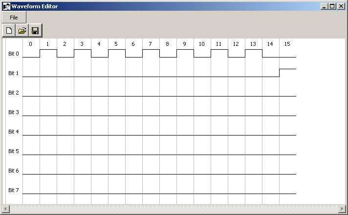
2.2.1 Continuous Sweep
If you selected Cycle Up Down, Sweep Up, Repeat or Sweep Down, Repeat, to start the sweep move to the main
waveform generator screen, Frequency Sweep controls. Click on Enabled. The generator will now sweep between
the two limits. The position of the Frequency slider moves to indicate progress of the sweep.

2.2.2 Sweep Trigger Output
When ’Enable Sweep Trigger Out (PWM2) is checked, a logic level sweep trigger signal is available at the PWM2
output terminal on the rear panel connector. This signal could be used by an oscilloscope to cause the beam of the
scope to start at the same time as the beginning of a frequency sweep.
    The signal is logic high during sweep up and logic low during sweep down. This signal can be most easily
seen when the Sweep Behaviour is set to ’Cycle Up Down’. On the main control panel, set Frequency Sweep: to
Enabled. The Frequency slider should move up and down and the output frequency change. The sweep trigger
signal then readily visible.
    During Sweep Behaviour: Sweep Up, Repeat or Sweep Behaviour: Sweep Down, Repeat the logic level signal
goes low for about 50mSec during the sweep reset.

2.2.3 Sweep Trigger Input
The sweep may be initiated by a logic level signal applied to the Counter/Trigger BNC input connector on the
front panel of the unit. This can be useful in synchronizing the sweep generator to an external device such as an
oscilloscope.
    To trigger the sweep:

   • In the Frequency Sweep Settings panel under Sweep Trigger select Counter Trigger Input.
   • In the Counter panel under Trigger Level, select a suitable level. For example, the default of 2.5 volts is
     appropriate for many logic level signals greater than 2.5 volts. The trigger voltage may be larger than +5
     volts, as much as 10 volts. Internal clamps will protect the trigger circuitry. For example, a 9 volt battery
     makes a convenient trigger signal.
   • Any of the Sweep Behaviour modes can be triggered. In the Repeat modes (Cycle Up Down, Sweep Up
     Repeat, Sweep Down Repeat), one trigger initiates sweeps, which will then continue indefinitely without
     further triggers. In the Reset modes (Sweep Up Reset, Sweep Down Reset), one trigger initiates one sweep
     and reset.
   • During the frequency sweep, the Frequency slider moves and the Disabled/Enabled button on the main
     panel changes from Disabled to Enabled.

3 Tone Burst
These controls are in the Trigger Controls panel, figure 4.

   • For normal continuous waveform output operation of the generator,
     set Trigger Mode to Free-Running and Output Mode to Continuous.
     (This is the power-on default setting.)
   • For continuous generation of tone bursts, set Trigger Mode to Free-
     Running and Output to Tone Burst. The tone burst pattern is speci-
     fied by the Trigger Cycles On, Off settings. Trigger Cycles On sets
     the number of complete cycles in the burst. Trigger Cycles Off sets
     the number of cycles between bursts. Trigger Cycles Repeat has no
     effect. The maximum count for Trigger Cycles On and Trigger Cy-
     cles Off is 65535.

                                                         6
• For manually triggered generation of a tone burst, set Trigger Mode
to Triggered and Output Mode to Tone Burst. Set Trigger Source to
Manual.
The tone burst pattern is specified by the Trigger Cycles On, Off set-
tings. Trigger Cycles On sets the number of complete cycles in the burst.
Trigger Cycles Off sets the number of cycles between bursts.
Trigger Cycles Repeat effectively sets the number of tone bursts.
The total number cycles is constrained, according to the follow-
ing:
(Non + Nof f ) × Nrepeats < 216
where
Non is the number of ON cycles in each burst
Nof f is the number of OFF cycles in each burst
Nrepeats is the number of tone burst repeats.
A tone burst is best observed with a digital storage oscilloscope set to Single Shot. On the generator, set up
the tone burst configuration as above. Set the scope to single-shot triggering. Reset the scope sweep. Actuate
Manual Trigger on the generator. The scope should capture the desired tone burst.
Figure 5: Tone Burst Oscilloscope Display
Figure 5 shows these tone bursts captured by a Syscomp CGR-101 CircuitGear oscilloscope in single-shot
mode.
3.1 Triggered Tone Burst
It is possible to use an external trigger signal to initiate each tone burst from the WGM-201 generator. Here is an
example configuration. In this example, we describe a configuration using the CircuitGear CGR-101 generator to
provide the trigger signal and the CircuitGear CGR-101 oscilloscope to display both the trigger signal and tone
7burst. However, any generator that can produce a suitable trigger signal may be used to provide the signal. Any
oscilloscope may be used to observe the trigger and tone burst.
1. Start both the CGR-101 software and WGM-201 software. The screen will be rather crowded at that
point. You can minimize the program you are not using at any given instant. You can also minimize
the Pulse Controls and Pattern Generator panels of the WGM-201, since they are not needed
for this exercise.
2. The tone burst trigger signal originates in the CGR-101. Connect the CGR-101 generator output to Channel
A of the CGR-101 scope, so that you can see the trigger signal. Connect that same signal to the front panel
counter/trigger input BNC connector on the WGM-201 generator.
3. At the trigger source (the CGR-101 generator) set a waveform frequency of about 20Hz or so to start with.
Set the amplitude to 55 (±1V) and the waveform to square wave. Trigger the scope from this signal. Check
that this signal appears on Channel A of the CGR-101 oscilloscope.
4. Connect the output of the WGM-201 generator to channel B of the CGR-101 scope.
5. Check that WGM-201 waveform generator trigger is operating properly:
• On the ’Counter’ panel, Counter Mode, select ’Event’.
• On the same panel, adjust the trigger slope and level until you see the counter readout (at the top of
the panel) incrementing.
6. Set up the Trigger Controls panel:
Waveform Generator Trigger Mode Triggered
Waveform Generator Output Mode Tone Burst
Pattern Generator Trigger Mode (shouldn’t matter)
Trigger Source Counter Input (Do not select External, that input is on the rear panel of the WGM-
201, and accepts a logic signal.)
7. For a tone burst of 3 on, 2 off, set:
On 3
Off 2
Repeats 1
8. Set the WGM-201 waveform generator amplitude output to 18 (±1V), frequency to 112 Hz or so.
On the oscilloscope display, you should see a burst of 3 cycles coincident with the rising edge of the square
wave trigger, with very little delay between the trigger signal and start of the tone burst.
Now that you have a basic tone burst configuration operating, you can change the control parameters to the
values you want.
4 Pulse Generator
The instrument has two independent pulse generators. For each generator,
the duty cycle and frequency can be set independently. That is, changing
the duty cycle has no effect on the frequency and vice versa.
The duty cycle is defined as the ratio of ON time to the period of the
waveform. During the ON time, the waveform is at +5V. During the re-
mainder of the period (the OFF time) the waveform is at zero volts.
8• Adjusting duty cycle independent of frequency is useful when test-
ing certain types of switch mode power supplies and power control
circuits.
• An adjustable duty-cycle waveform may be used as the basis for
digital to analog conversion. If the waveform is low-pass filtered,
the resultant average is proportional to the duty cycle.
• Spectrum analysis of a variable duty cycle signal is illustrative of the
princibles of Fourier Analysis.
Each pulse generator output has its own control panel, figure 6. One of
these control panels is visible at a time, selected by a switch at the top of
the panel, which shows Channel 1 or Channel 2.
Pulse generator output signals swing from 0V to +5V. The two signals
and ground connections are available on the rear-panel connector of the
instrument (section 10).
The pulse generator controls are identical for Channel 1 and Channel
2.
The output is enabled or disabled by radio-buttons under PWM1 (or-
PWM2) Output: When an output is disabled, the frequency and duty cycle sliders are frozen.
As in the case of the core waveform generator, the frequency may be set by direct entry. Left-click on the
frequency display in the pulse generator panel. This causes an entry widget to appear. Enter the desired frequency
and then left-click on OK.
9The frequency slider operates in the same manner as the core waveform generator. The control may be dragged
between the maximum and minimum values. Clicking on the slider area outside the button causes the frequency to
increment or decrement. The maximum and minimum frequencies are set by clicking on their respective displays
and typing in suitable values. The Sweep Mode (control characteristic) may be selected as logarithmic or linear.
A second slider sets the duty cycle of the output waveform.
In general, the pulse generator outputs are unsynchronized with each other and the main generator output.
However, if the two pulse generator frequencies are set to the same value, they will remain in a fixed (although
arbitrary) phase relationship. This is also true if one pulse generator output frequency is an integer multiple of
the second output. The two frequencies can also be made to walk with respect to each other. For example, if one
frequency is set to 400.0 Hz and the other to 400.1 Hz, then the two frequencies will appear to drift past each
other, one complete cycle every 10 seconds.
Similarily, the two pulse generator outputs will synchronize with the main output if they are set to exactly the
same frequency.
5 Pattern Generator
The pattern generator produces a series of 8 bit data words at the
rear panel connector (section 10 on page 21). The sequence length
may be any binary value from 4 to 1024 words.
The pattern generator is controlled from the Pattern Generator
Control Panel, figure 7. The frequency slider sets the frequency of
the repetition rate of the sequence. For example, if the sequence
length is set to 32 words and frequency slider set to 1000Hz, then
the 32-word sequence will repeat 1000 times per second. The
maximum bit toggle rate is 10MHz.
The software automatically calculates and adjusts the maxi-
mum pattern frequency to keep the sample rate below 10MHz.
i.e. The maximum frequency for a 1024 sample pattern is 20kHz,
40kHz for a 512 sample pattern, 80kHz for a 256 sample pattern,
etc.
The rear-panel pattern-generator trigger signal goes to logic
low at the beginning of each sequence and high approximately
half-way through the sequence. This is true for any pattern length.
As in the core waveform generator and pulse generator con- Figure 7: Pattern Generator Control Panel
trols, the frequency may be set by direct entry (click on the fre-
quency display), by dragging the slider, or by clicking in the slider
area outside the button. The maximum and minimum frequency
settings may be changed by clicking on them and entering new
values.
5.1 Creating a Digital Pattern
We’ll use an example to illustrate this process. We assume that our digital logic needs 7 shift pulses on one pin,
followed by a load pulse on another pin.
1. Click on the Pattern Generator panel Edit Waveform button.
2. The pattern editor panel displays.
3. Click on the pattern editor ’blank sheet’ icon.
4. The New Waveform Select Sequence Length panel appears. Select the desired sequence length. in this case
we select a sequence length of 16.
5. The pattern editor panel displays 8 traces with timing marks from 0 to 15.
10Figure 8: Pattern Editor
6. Click on a bit cell to change its state from zero to one or vice versa.
7. On the Bit 0 line, create 7 logic ones in a sequence, each separated by a logic zero.
8. On the Bit 1 line, create a single logic 1 in the #15 time slot. The pattern editor should appear as in figure 8.
9. Click on the floppy disk icon and save the file.
10. Return to the Pattern Generator panel and click on ’Load Waveform’. In the load dialog, select the previ-
ously saved file.
11. The pattern should now appear at the rear panel connector.
Figure 9: Pattern Demonstration
The resultant computer display, captured by a Syscomp CGR-101 oscilloscope, is shown in figure 9. The
upper trace shows 7 shift pulses in sequence. The lower trace shows the single load pulse.
115.2 Pattern File Format
The pattern file is a text file, so it can be edited in any text editor (such as Notepad on a Windows machine). The
first entry is the number of time slots (16 in our example). This is followed the one byte value for each time slot
entry. In our example, the last entry is ’2’ because there is a single binary 1 on the Bit 1 line, which has a binary
weight of 2.
126 Counter
The Counter is a general purpose event and frequency counter. In the
Events mode, the counter increments with each trigger pulse, up to a max-
imum of 23 1 − 1 (approximately 2 × 10⁹ ) counts. A manual reset restarts
the counter from zero.
The counter input connector is the right-hand BNC connector on the
front panel.
In the Frequency mode, the counter measures the input frequency to an
accurancy of ±50 ppm (±0.005%).
Counter trigger controls allow one to select the slope of the trigger
(rising or falling edge) and the voltage (±5V, approx.)
The counter input signal, processed by the trigger slope and level, can
be used to trigger a tone burst. Select Trigger Source: Counter Input.
This same trigger signal can be conditioned to delay a number of se-
lected cycles. For example, one could set up the generator to produce a tone
burst when 1000 events have occurred. Select Trigger Source: Counter
Threshold. Click on the numbered button below Counter Threshold. An
entry widget pops up. Enter the number of cycles in that entry.
Counter threshold triggers only once and then must be manually reset.
7 Arbitrary Waveform
A waveform for the WGM-201 is stored as a text file consisting of 256, 8
bit bytes with a .dat suffix. Look for sine.dat as an example. Most
negative value of a waveform is coded as 255. Most positive value is coded
as 0.
Any program that can create this type of file can be used to create wave- Figure 10: Counter Panel
form. For example, you could hand-code the file using a text editor pro-
gram like Notepad, although this would be rather tedious.
If the waveform can be described by a formula, then you can use a spreadsheet to create the necessary file.
Use the formula to create 256 values of the waveform such that all the values are in the range 0 < x < 255.
Copy the waveform values to a new sheet. Save that sheet as a .csv format file. Review the file in an editor and
remove any extraneous characters by search and replace.
When creating and generating an arbitrary waveform, Keep in mind the constraints described in sections 7.1
and 7.2, below.
7.1 Low and High Frequency Settings
At low frequency, the waveform memory address remains constant for a number of clock cycles. As a waveform
is produced, all the addresses in the waveform memory are accessed, in ascending order, each for several clock
cycles. Consequently, the waveform includes 256 horizontal steps.
At some intermediate frequency, each and every clock pulse results in an increment of the waveform address.
Each point on the waveform is produced exactly once. At this frequency (call it fmid ), the period of the generated
waveform (call it Tmid ) is given by:
Tmid = Points in one waveform × Tclock
= 28 × 600 nsec
= 154µsec
This period corresponds to a frequency of:
1
fmid =
Tmid
131
=
154µsec
= 6493.5 kHz
Above that frequency, some addresses in the waveform memory are skipped. As a result, the waveform
contains fewer than 256 horizontal points.
At very high frequencies, the number steps in the waveform decreases to the point that the waveform steps
become visible. The waveform becomes ’blocky’. There is a tradeoff between the quality of the waveform and
the maximum useable frequency of operation.
In this generator, the default maximum frequency (seen at the top of the frequency slider) has been set at
3MHz. This is under the control of the user. Click on that display and enter a new maximum value. Quite
satisfactory sine waves can be obtained at 10MHz.
7.2 Detail in Arbitrary Waveforms
The basic nature of a sampled-data system the lowpass filter in the signal chain places a restrictions on the shape
of the arbitrary waveform. The highest frequency content in the arbitrary waveform cannot exceed the capability
of the output amplifier in the generator. As a rule of thumb, the highest reproduced frequency should be less than
the maximum generator sine wave frequency, which is 10MHz.
For example, suppose the arbitrary waveform consists of a four cycles of a sine wave. When the frequency is
set to 10MHz, the effective output frequency is 40MHz, which is beyond the capability of the generator output
amplifier.
You are free to experiment with this, to see if the generator can reproduce the required detail at the maximum
operating frequency.
7.3 Waveform Editor
John Foster has developed the Wavemaker program to allow editing of a generator waveform, using a graphical
user interface. Wavemaker is started from the Tools menu. The Wavemaker manual is available from the
Help manual.
8 Synchronizing Two Generators
Two or more generators my be synchronized. On their rear panel connectors, the waveform trigger out
pin of generator #1 (the master) is connected to the waveform trigger in pin of generator #2 (the slave).
(a) Waveforms (b) Expaned View
Figure 11: Synchronized Waveforms
14The slave generator must be set to a very slightly higher frequency than the master, so that each waveform
cycle completes before there is a new trigger signal2 .
Figure 11 shows the master waveform producing a 400Hz square wave. The slave is producing a 400Hz sine
wave3 . The expanded view shows a flat spot on the slave waveform where it is waiting for the next trigger signal.
9 Commands
In this section we document commands that may be issued directly to the hardware. The terminal emulator
or programming language that sends these commands appears to do so using a a serial port connection to the
hardware. It is not necessary to deal with USB in any form. Consequently, any language that can send and receive
commands via a serial port can communicate with the WGM-201 hardware.
9.1 Setting up the Terminal: Overview
We recommend first testing the connection using a terminal emulator. A terminal emulator (such as Hyperterminal
in Windows or Seyon or Minicom in Linux) can be used to send commands to the hardware, and this verifies that
the serial connection is working properly.
When the WGM-201 software is running correctly (ie, Connected), actuate Hardware -> Connect -> Port
Settings and determine the COM port (serial port) being used by the GUI (graphical user interface).
Shut down the GUI so that it’s not trying to use the serial port. The serial port needs to be available to the
terminal emulator program.
Start the terminal emulator and connect to that COM port. (On a Linux machine it’s probably a ttyUSBx
port, where x is the number of the port.) Set the terminal emulator parameters to 8 bits, no parity, one stop bit.
Since the serial port is a VCP (virtual COM port) that is actually USB, the baud rate is unimportant.
With the WGM-201 hardware connected, you should now be able to send commands to the hardware. The
first command to try is the Identify command. Send i followed by a carriage return. The right-hand LED on
the hardware should flash, since the hardware received a character and has sent a string. The identification string
(see table, below) should appear on the terminal screen.
9.2 Terminal Emulator under Windows
Some versions of the Windows operating system have Hyperterminal installed, which can act as a terminal emu-
lator. However, Hyperterminal does not provide convenient access to the setup parameters and is difficult to use.
We installed and used the open-source software TeraTerm instead.
1. Download and install the TeraTerm software from Sourceforge:
http://en.sourceforge.jp/projects/ttssh2/releases/
This should create a TeraTerm icon on your desktop.
2. Plug in the WGM-201 hardware to an unused USB port.
3. Start TeraTerm. The ’New Connection’ window appears. ’TCP/IP’ is selected by default. Change the
selection to ’Serial’.
4. On that same window, select ’Port’. In this case, it shows COM3 and COM5: USB Serial Port.
Select COM5. Click on OK. Window closes.
5. Select the menu item Setup -> Serial Port
The port has been selected, no need to change that.
Set the Baud Rate to 230400.
Set Data Bits to 8.
Set Stop Bits to 1
Set Parity to None
2 This is triggered operation, not a phase-lock. Changing frequency requires changing frequency on both master and slave.
3 On the todo-list is a control for jogging the phase of the two waveforms.
15Set Flow Control to Hardware.
Click on OK. Window closes.
6. Select the menu item Setup -> Terminal
Change the New-line Receive to CR+LF
Change the New-line Transmit to CR+LF
Click on OK. Window closes.
7. In the main terminal window, type the letter i followed by the Return key. You should see a message
something like *Syscomp Advanced Waveform Generator V1.0/1.0.
If so, you are now connected and can issue commands to the generator. Notice that all commands are
terminated by the Return key.
8. Example: The command A 128 sets the amplitude to 5 volts.
Example: The command W 1 sets the waveform to Triangle.
9.3 Command Listing
The commands that are used to control the WGM-201 hardware are shown in the following tables.
All commands are terminated by a carriage return character. A terminating line-feed character is ignored.
General
i Identification string request. Returns: *Syscomp Advanced Waveform
Generator VX.XX where X.XX is the firmware revision.
Function Generator
A Amplitude, sets peak voltage of waveform.
Usage: A nnn where nnn is an 8 bit ascii number ranging from 0 to 255, representing the
amplitude.
Output amplitude = (nnn/255) ∗ 10V
Example: A 127 sets the amplitude to 5 volts.
F Frequency Command. Usage: F aaa bbb ccc ddd where aaa through ddd are 8 bit
ascii numbers that make up a 32-bit number (YYYY) to set the output frequency. Output
frequency = YYYY*0.031247735 [Hz] (See below for an example).
O Offset command. Usage: O nnn where nnn is an 8 bit ascii number representing the
offset. Output offset = ((127 − nnn)/127) ∗ 10V
Wn Select waveform, where n is one of the following.
0 - Sine
1 - Triangle
2 - Square
3 - Sawtooth
4 - User
Sad Write volatile [1] waveform sample into device.
a - eight bit address
d - eight bit data
Jad Write semi-permanent [1] waveform sample into device buffer memory.
a - eight bit address
d - eight bit data
Q Write the data loaded into the buffer (with the J command) to the non-volatile memory.
U Recall waveform from the non-volatile memory.
Also returns the entire waveform (256 bytes) preceeded by the W character
E Enable waveform output [2]
e Disable waveform output
N Enable noise output [2]
n Disable noise output
16Trigger Commands
Mn Select trigger mode, where n is one of the following.
0 - Waveform Generator Free-Running Mode
1 - Waveform Generator Triggered Mode
2 - Pattern Generator Free-Running Mode
3 - Pattern Generator Triggered Mode
V0 Select continuous output
V1 Select tone burst output
Xn Select trigger source, where n is one of the following.
0 - External Trigger
1 - Manual Trigger
2 - Counter Trigger
3 - Counter Input
Yab Set trigger count command
Parameters a and b make up a 16 bit number which determines how many waveform or
pattern generator cycles are executed in triggered mode.
Zab Set tone burst ON cycles
Parmeters a and b make up a 16 bit number which determines how many waveform cycles
are output in tone burst mode.
zab Set tone burst OFF cycles
Parmeters a and b make up a 16 bit number which determines how many waveform cycles
the generator is idle in tone burst mode.
T Manual Trigger Command
Labcd Counter trigger threshold command
Parameters a b c d make up a 31 bit threshold value for the counter. Byte a is the
MSB, byte d is the LSB. When the counter value exceeds this threshold a counter trigger
is generated which can be used to trigger the waveform generator or pattern generator
PWM Commands
Pcn PWM Duty Cycle Command
Parameter c is the channel number, either 1 or 2.
Parameter n is an eight-bit duty cycle value:
Duty Cycle = (255 − n)/255 ∗ 100%
Geabcd PWM Frequency
Parameter e is the channel number, either 1 or 2.
Parameters a b c d specify the frequency.
(See Frequency command, and example below.
1 Enable PWM 1 output
! Disable PWM 1 output
2 Enable PWM 2 output
@ Disable PWM 2 output
17Pattern Generator Com-
mands
3 Enable Pattern Generator Output
# Disable Pattern Generator Output
Habcd Set Pattern Generator Frequency (frequency of the repetition rate of the sequence.)
Parameters a b c d specify the frequency. See Frequency Command above.
Bhld Set Pattern generator sample
Enters a pattern value d at pattern address hl where h is the high byte, l is the low byte.
ln (the command is lower case ’ell’)
Pattern Generator Length. The parameter n specifies the pattern length, as follows:
0: 1024 samples
1: 512 samples
2: 256 samples
3: 128 samples
4: 64 samples
5: 32 samples
6: 16 samples
7: 8 samples
8: 4 samples
9: 2 samples
Counter Commands
Dn Counter Mode
0: Normal Counter (Accumulator)
1: Frequency Counter (Period = 1/64 sec)
2: Frequency Counter (Period = 1/32 sec)
3: Frequency Counter (Period = 1/16 sec)
4: Frequency Counter (Period = 1/8 sec)
5: Frequency Counter (Period = 1/4 sec)
6: Frequency Counter (Period = 1/2 sec)
7: Frequency Counter (Period = 1 sec)
8: Frequency Counter (Period = 2 sec)
C nn Counter Trigger Voltage Level
where nn as an 8 bit ASCII value representing
the trigger threshold voltage:
Trigger Level = (nn − 127)/127 ∗ 10 volts
R Read Counter
Returns 4 bytes corresponding to the 32 bit counter value, high byte first.
r Reset Counter
+ Sets trigger polarity to rising edge.
- Sets trigger polarity to falling edge.
Notes:
[1] A volatile sample is one sample of the arbitrary waveform. It is volatile because it is held in RAM, so it
disappears when the power is disabled. A total of 256 8 bit samples constitute a waveform and will show as the
current output waveform.
A semi-permanent sample is written into the hardware EEPROM. It does not appear immediately in the output
waveform. It is transferred into the waveform RAM and appears in the output with the Select waveform -
User command W 4.
[2] Enable Waveform output enables and disables all waveforms, including noise. Enable Noise enables and
disables only the noise source. When noise is enabled, other waveforms (such as Sine) are disabled and vice versa.
Converting Frequency
Here we show the example of converting output frequency of 2MHz into a command.
181. Convert the desired output frequency into the correct count, using the conversion factor.
2 × 10⁶ Hz
2MHz =
0.031247735 Hz/Count
= 64004639 Counts
2. Convert this value to a hexadecimal number. (Some scientific calculators have this function, or use the web
site http://www.statman.info/conversions/hexadecimal.html
64004639 base 10 = 3d0a21f hexadecimal (base 16)
3. Group the hex number by pairs starting at the right end. Convert each pair to the corresponding decimal
number, which will range from 0 to 255. Again, use a calculator for each pair, or the website mentione
previously.
3d0a21f = 3 d0 a2 1f
= 3 208 162 31
You can verify that this is correct. Use View -Debug Console to enable the console, which shows
messages being set to the hardware. Click on the frequency readout, enter the frequency value 2000000
into the New Frequency widget. You will see the message F 3 208 162 31 sent to the hardware.
Trigger
Mn Select trigger mode, where n is one of the following.
0 - Waveform Generator FreeâĂŘRunning Mode
1 - Waveform Generator Triggered Mode
2 - Pattern Generator FreeâĂŘRunning Mode
3 - Pattern Generator Triggered Mode
Xn Select trigger source.
0 - External Trigger
1 - Manual Trigger
2 - Counter Trigger
Yab Set trigger count command.
Parameters a and b make up a 16-bit number which dictates how many waveform or pat-
tern generator cycles are executed in triggered mode. It uses an count up counter which
overflows at 65536 so you program it with 65536 minus the number of cycles you want
it to output after the trigger. Using Y 0 1 would output 65536-1=65535 cycles of the
waveform after a trigger.
T Manual trigger
Pulse Generator
Pcn pulse generator duty cycle command.
Parameter c is the channel number. Valid values are 1 and 2.
Parameter n is an eight-bit duty cycle value. 0 is off, 255 is fully on.
Gcabcd pulse generator frequency.
Parameter c is the channel number. Valid values are 1 and 2.
Parameters a b c d make up frequency integer (see frequency command)
1 Enable pulse generator 1 Output
! Disable pulse generator 1 Output
2 Enable pulse generator 2 Output
@ Disable pulse generator 2 Output
19Pattern Generator
3 Enable pattern generator output.
# Disable pattern generator output.
Habcd Pattern generator frequency. (See frequency command)
Bhld Pattern generator sample command.
Parameters h and l are the high and low bytes of a 10-bit address value.
Parameter d is an 8 bit sample value.
Counter
C Counter threshold. Usage:
C nnn where nnn is an 8 bit ascii number representing the counter threshold voltage.
Threshold voltage = ((127 − nnn)/127) ∗ 10V.
R Read counter
Command returns 5 bytes, Cuvwx where uvwx correspond to a 32-bit counter value, high
byte first.
r Reset counter to zero.
+ Select positive counter trigger polarity
− Select negative counter trigger polarity
Example: Single Cycle Tone Burst
Here we show the generation of a single cycle tone burst from commands to the hardware. We determined the
commands by executing them on the GUI by hand, while reading the ASCII strings that the host PC was sending
to the hardware.
Here is the manual operation:
1. Start GUI
2. Set output amplitude (and waveform, and frequency, if required)
3. Select Triggered under Waveform Generator Trigger Mode
4. Select Manual under Trigger Source
5. Set Repeat under Trigger Cycles to 1
6. Press the manual trigger button to generate one cycle
Here are the corresponding commands:
A 128 Amplitude control
M 1 Select trigger mode, 1=Triggered mode
Y 255 255 Number of repeat cycles, see below
X 1 Select trigger source, 1=Manual trigger
T Execute manual trigger
To calculate the number of repeat cycles (number of output cycles per trigger): the 16-bit register setting is
given by
65536 − (Number of cycles)
(eg) For three output cycles:
Register Setting = 65536 − 3 = 65533
This value is sent to the hardware in two 8-bit bytes, a high byte (255) and a low byte (253). The command is
then Y 255 253.
(eg) For one output cycle:
Register Setting = 65536 − 1 = 65535
The command is Y 255 255
2010 Rear Panel Connector
The rear panel connector provides access to the following signals:
• Digital Pattern outputs 0 through 7
• Trigger signals for the waveform generator, pattern generator and counter.
– Waveform Trigger Out A logic level signal that goes high at the beginning of each waveform. It
goes low at approximately the mid-point of the waveform.
– Pattern Generator Trigger Out A logic level signal that goes low at the beginning of each pattern
sequence. It goes high at approximately the mid-point of the pattern.
– Counter Trigger Out A logic level signal that corresponds to the counter trigger signal.
• Pulse Generator outputs (2)
• External trigger input
• Ground
Counter Trigger Out
PWM1 out Pattern Generator Trigger Out
PWM2 out Waveform Trigger Out
GND External Trigger In
..... ..... ..... ..... ..... .. .. ..... ..... ..... .....
.... .... .... .... Key ......
... .... .... ... ....
2 4 6 8 10 12 14 16 18 20
....... ....... ....... ....... ....... ....... ....... ....... ....... .......
.... .... ..... .... .... .... ..... .... ..... .... ..... .... .... .... ..... .... ..... .... ..... ....
........ ........ ........ ........ ........ ........ ........ ........ ........ ........
....... ....... ....... ....... ....... ....... ....... ...... ...... ......
... .... .... ..... ... .... .... ..... .... ..... .... ..... ... .... ..... ..... ..... ..... ..... .....
....... ....... ....... ....... ....... ....... ....... ....... ....... .......
1 3 5 7 9 11 13 15 17
.
19
.
.... .
....
.... .. ..
0 1 2 3 4 5 6 7
GND
Digital Pattern Outputs
WGM-201 Waveform Generator
Rear Panel Connector
View toward rear panel
Figure 12: WGM-201 Rear Panel Connector Pinout
The pinout is shown in figure 12 and on the case label of the instrument.
10.1 Rear Panel Connector Mating Plug
One suitable rear panel connector mating plug is as follows:
MODE part # 35-0202-0
20 position, 2 row, 0.1" (2.54mm) contact spacing.
Mates with 20 way 0.050" spacing flat cable.
Polarizing key (Centre bump)
Strain Relief
Available from MODE Electronics, http://www.mode-elec.com
Distributed by Active-Tech Electronics in Canada, http://www.active123.com
Another suitable connector is this one:
213M part # D89120-0131HK
Digikey part # MKC20E-ND
20 position, 2 row, 0.1" (2.54mm) contact spacing.
Mates with 20 way 0.050" spacing flat cable.
Polarizing key (Centre bump)
Contacts 10u gold plate
Mating strain relief for this connector:
3M part # D3448-89120
Digikey part # MESR20-ND
Available from Digikey, http://www.digikey.com
Any flat cable with 0.050" conductor spacing that will mate with IDC (Insulation displacement connector)
should be suitable for use with these plugs. For example:
3M 3302 Series
Digikey part # MCM-20M-5-ND (5 foot length)
10 colour repeat, clear carrier
11 Creating an Arbitrary Waveform
The WaveMaker Waveform Editor 4 is available under the Tools menu. Select that item and the blank waveform
edit screen pops up.
For WaveMake instructions, select the Help -> Manual(PDF) on the waveform edit screen. (If for some
reason that fails, check in the install directory, Source subdirectory. The manual file should be there as a pdf
which you can open with Acrobat reader.).
4 Contributed by John Foster. Thanks, John!
22You can also read