Large flux-mediated coupling in hybrid electromechanical system with a transmon qubit - Nature
←
→
Page content transcription
If your browser does not render page correctly, please read the page content below
ARTICLE
                  https://doi.org/10.1038/s42005-020-00514-y                OPEN

                  Large flux-mediated coupling in hybrid
                  electromechanical system with a transmon qubit
                  Tanmoy Bera1,2, Sourav Majumder1,2, Sudhir Kumar Sahu1 & Vibhor Singh                                         1✉
1234567890():,;

                  Control over the quantum states of a massive oscillator is important for several technological
                  applications and to test the fundamental limits of quantum mechanics. Addition of an internal
                  degree of freedom to the oscillator could be a valuable resource for such control. Recently,
                  hybrid electromechanical systems using superconducting qubits, based on electric-charge
                  mediated coupling, have been quite successful. Here, we show a hybrid device, consisting of a
                  superconducting transmon qubit and a mechanical resonator coupled using the magnetic-
                  flux. The coupling stems from the quantum-interference of the superconducting phase across
                  the tunnel junctions. We demonstrate a vacuum electromechanical coupling rate up to 4 kHz
                  by making the transmon qubit resonant with the readout cavity. Consequently, thermal-
                  motion of the mechanical resonator is detected by driving the hybridized-mode with mean-
                  occupancy well below one photon. By tuning qubit away from the cavity, electromechanical
                  coupling can be enhanced to 40 kHz. In this limit, a small coherent drive on the mechanical
                  resonator results in the splitting of qubit spectrum, and we observe interference signature
                  arising from the Landau-Zener-Stückelberg effect. With improvements in qubit coherence,
                  this system offers a platform to realize rich interactions and could potentially provide full
                  control over the quantum motional states.

                  1 Department of Physics, Indian Institute of Science, Bangalore 560012, India. 2These authors contributed equally: Tanmoy Bera, Sourav Majumder.
                  ✉email: v.singh@iisc.ac.in

                  COMMUNICATIONS PHYSICS | (2021)4:12 | https://doi.org/10.1038/s42005-020-00514-y | www.nature.com/commsphys                                        1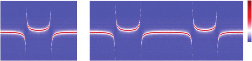
ARTICLE                                                              COMMUNICATIONS PHYSICS | https://doi.org/10.1038/s42005-020-00514-y

C
        avity optomechanical systems, where a mechanical mode              By shunting the SQUID “inductor” to a suitable capacitance, a
        parametrically modulates the resonant frequency of an              transmon qubit mode can be designed. As the motion of the
        electromagnetic (EM) mode, have been very successful in            mechanical resonator directly affects the qubit transition fre-
controlling the motional states of massive oscillators1. Starting          quency, this coupling is referred to as longitudinal coupling. A
from the earlier demonstration of the motional quantum ground              flux-coupled hybrid system formed this way can be thought of a
state by the sideband cooling technique2,3, these experiments              dual to the “charge” coupling approach realized with the Cooper-
have reached several milestones related to the displacement-               pair box qubit16.
detection4 and the preparation of the non-classical states of                 Theoretically, the flux-mediated electromechanical coupling
mechanical motion5,6. Beyond the traditional two-mode systems,             has been considered in the context of flux-qubits23, cavity-
consisting of one EM and one mechanical mode, cavity opto-                 electromechanical devices24, and more recently with the trans-
mechanical systems with an auxiliary mode provides a wide range            mon qubit21,25. On the experimental side, the scheme has been
of interactions. Such systems have been used to realize non-               used for large bandwidth displacement detection26, and to
reciprocal devices7–9, and to demonstrate quantum entanglement             demonstrate the cavity-electromechanical system by embedding
between two mechanical resonators10,11.                                    Josephson elements in the microwave circuitry27,28.
   Among the two-mode cavity optomechanical devices, pre-                     In comparison to existing flux-coupling approaches27,28, our
paration of the quantum states of motion appears to be techno-             design methodology circumvents several issues by using a tunable
logically challenging. One successful strategy in the microwave            transmon mode. First, the requirement of large Josephson
domain, to circumvent this, is to introduce an auxiliary nonlinear         inductance for transmon design helps in suppressing hysteretic
mode such as a qubit. The qubit can be used as a single-photon             effects with magnetic flux arising from geometrical and kinetic
source12, photon-counter13, or directly coupled to a mechanical            inductance. Second, our approach here is to implement a
mode using its charge dispersion14–17 or the piezo-electric                longitudinal coupling between transmon qubit and a mechanical
effect18–20. In such devices, the qubit mode “acts” like an addi-          resonator through the modulation of Josephson inductance. This
tional degree of freedom which couples to mechanical mode via              enables the interaction of the mechanical mode with the qubit in
an intermediate mode or directly using the “charge” dispersion.            two distinct ways. First, due to strong coupling between the qubit
   While systems utilizing the charge-based coupling have been             and cavity in the resonant limit, the mechanical motion directly
studied extensively, the experimental progress of the hybrid sys-          couples to the hybridized states. Second, in the dispersive limit
tems based on magnetic-flux has been very limited. Here we                  when the qubit is detuned far away from the cavity, a sufficiently
design and study the performance of a hybrid electromechanical             large coupling between the qubit and the mechanical mode can
device based on a fundamentally different coupling scheme based            be maintained. It thus provides a mean to use the qubit as an
on the magnetic flux. We engineer the device parameters such                internal degree of freedom to the mechanical mode and
that in addition to the flux-based electromechanical coupling, one          further paves ways for measurement-based cooling and control
mode maintains sufficient anharmonicity to be qualified as a                 protocols25,29,30.
qubit. This approach results in an electromechanical system with
an internal spin-half degree of freedom. By recording the ther-
momechanical motion of the resonator, we demonstrate a mag-                Device design. We use a three-dimensional (3D) cavity to
netic field tunable electromechanical coupling rate up to 4 kHz             implement the transmon design as shown schematically in
when qubit is tuned in resonance with the cavity. On one                   Fig. 1c. Unlike the conventional 3D-transmon qubit, which
hand, the strong and tunable nonlinearity of the qubit mode                couples differentially to the cavity mode, we design a single-ended
improves the displacement sensitivity. On the other hand, the              qubit mode by grounding one end of the SQUID loop to the
large electromechanical coupling modifies the qubit spectrum in             cavity wall using a small wirebond31. The other end of the
the dispersive limit. As a consequence, we observe the                     SQUID loop extends toward the center of the cavity and provides
Landau–Zener–Stückelberg (LZS) interference in the qubit spec-             the necessary qubit capacitance and coupling with the funda-
trum when the qubit is detuned in the dispersive limit. Similar to         mental cavity mode. The rectangular cavity (35 × 4 × 35 mm3) is
vacuum-electromechanical coupling rate’s scaling with total                machined using copper with the fundamental resonant mode
charge in charge-dispersion-based schemes14–16, the coupling               TE101 at ωc ≈ 2π × 6 GHz. A false-color scanning electron
rate here scales linearly with the magnetic field. Therefore, such          microscope (SEM) image of the SQUID loop is shown in Fig. 1d.
an approach has the potential to reach the elusive single-photon           The nanobeam-shaped mechanical resonator, formed by a 100-
strong coupling regime with suitable choice of materials21.                nm highly stressed SiN film coated with 50 nm of aluminum, and
                                                                           suspended part of the Josephson junctions can be clearly seen.
                                                                           Important device parameters are listed in the Supplementary
Results and discussion                                                     Note 1. The offset in the SQUID position (away from the center
Concept. The hybrid device consists of a transmon qubit coupled            of the cavity) in transmon design allows us to bring a RF drive
to a mechanical resonator and a readout cavity, as shown in                line for the electrostatic actuation of the mechanical resonator.
Fig. 1a. The transmon qubit couples to the cavity via a dipole             Results from design simulations are included in the Supplemen-
coupling, commonly referred to as transverse coupling, as it               tary Note 3.
connects the ground and the first excited state of the qubit22. The            The transmon qubit frequency ωq is given by _ωq
                                                                           qffiffiffiffiffiffiffiffiffiffiffiffiffiffiffiffiffiffiffiffiffiffiffiffiffiffiffiffiffiffiffiffiffiffiffiffiffiffiffi
mechanical resonator couples to the qubit via a flux-mediated
                                                                              8EC E0J jcosðπΦ=Φ0 Þj  EC , where E0J is the maximum Joseph-
coupling. Such coupling is achieved by embedding a mechanical
resonator into one of the arms of a SQUID (Superconducting                 son energy, EC is the charging energy, Φ is the total flux threading
Quantum Interference Device) loop, which provides the necessary            the SQUID loop, and Φ0 = h/2e is the magnetic flux quanta. The
Josephson inductance to form a transmon qubit. Due to the                  tunability of qubit frequency with flux allows access to its
quantum interference of the superconducting phase, the Joseph-             dispersive or resonant interaction with the cavity. The interaction
son inductance of the SQUID depends on the magnetic flux                    between the qubit and the cavity mode can be expressed as
threading the loop as schematically shown in Fig. 1b. In the               _Jð^aσ^þ þ ^ay σ^ Þ, where ^a(^
                                                                                                          σ  ) is the ladder operator for the cavity
presence of a magnetic field, applied normal to the plane of the            (qubit) mode and J is the dipole coupling rate. The electro-
SQUID, it acts like a displacement-dependent nonlinear inductor.           mechanical coupling arises from the modulation of qubit

2                       COMMUNICATIONS PHYSICS | (2021)4:12 | https://doi.org/10.1038/s42005-020-00514-y | www.nature.com/commsphys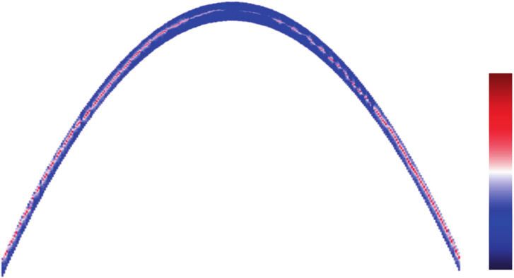
COMMUNICATIONS PHYSICS | https://doi.org/10.1038/s42005-020-00514-y                                                                    ARTICLE

              a                                                                                               b

               in
                              EM cavity                Transmon
                                                                                 mechanical                             Φ(x)
             out                                                                 resonator
                                                                                              mechanical
                                          transverse              longitudinal                drive

              c                                                         d

                                                          in

                                                          out
                    rf + dc
                                                                                 15 μm

Fig. 1 Device concept and design. a A schematic showing various components of the hybrid electromechanical system. The transmon qubit couples to
an electromagnetic cavity via the transverse coupling. A low-frequency mechanical resonator couples to the transmon qubit via the longitudinal coupling.
b A schematic of the SQUID loop with a suspended arm. Due to the magnetic flux Φ(x) dependence of Josephson inductance, it forms a displacement-
dependent inductor. c A cross-sectional view of a 3D-cavity based transmon device. The gray (white) portion represents the copper (machined chamber).
Input–output ports for microwave and a third port added for mechanical actuation is shown. The SQUID loop is placed inside a small recess of the cavity
schematically shown by the lighter gray area. d A false-color scanning electron microscope image of the SQUID loop, showing the suspended portion of the
Josephson junctions and the nanobeam. The mechanical resonator has a length and width of 45 μm and 300 nm, respectively. It consists of a 50-nm
coating of aluminum over a 100-nm-thick highly stressed SiN film. The T-shaped electrode in the lower-half of the image is used to actuate the mechanical
resonator.

frequency caused by mechanical displacement. As the qubit                          of qubit frequency, the vacuum Rabi splitting pattern repeats with
frequency can be tuned over a large range, it is convenient to                     every new flux-quanta added. The extension panel of Fig. 2a
define the vacuum electromechanical coupling rate between the                       shows the transmission measurement at a higher magnetic field.
qubit-cavity hybridized states ðω ± Þ and the mechanical resonator                 Apart from a small reduction (~15 MHz) in the maximum qubit
as,                                                                                frequency and an increase in the dressed-cavity mode linewidth,
                                                                                   we do not observe any significant change in the device parameters
                                ∂ω ± ðΦÞ            xzp                            up to a field of ~3.7 mT (310 Φ0).
                    g ± ðΦÞ ¼            xzp ¼ ΦGΦ±     ;                 ð1Þ
                                  ∂x                 w                                To understand the flux-transduction of hybridized modes, we
                                                                                   compute the flux-responsivity GΦ± using the measured qubit and
where GΦ± ¼ ∂ω ± ðΦÞ=∂Φ is the flux-responsivity, xzp is the                        cavity parameters and assuming identical junctions. Figure 2b
quantum zero-point fluctuations of the mechanical resonator,                        shows the plot of GΦ± with respect to the hybridized-mode
and w is the effective width of the SQUID loop. Equation (1)                       frequencies. The flux-responsivity of the hybridized modes
defines the coupling rate over the entireqffiffiffiffiffiffiffiffiffiffiffiffiffiffiffiffiffiffiffiffiffiffiffi
                                                 range of qubit                    increases as their relative detuning ðjω ±  ωc jÞ increases.
frequencies. The hybridized modes ω ± ¼ Δ ± ðΔ=2Þ2 þ J 2 with                     However, reduced transmission at frequencies far away from ωc
               ¼ ðωq þ ωc Þ=2 approach the uncoupled qubit                        hinders their use for the mechanical transduction. We choose an
Δ = ωq − ωc, Δ
                                                                                   optimum operating point of 6.025 GHz, corresponding to
and cavity frequencies in the dispersive limit. Restricting the                    GþΦ =2π  1.8 GHz/Φ0, for the mechanical resonator characteriza-
coupled qubit–cavity system to single excitation subspace, in the                  tion. This flux-responsivity is significantly larger than the values
resonant limit |Δ| ≪ J, the hybridized modes essentially act like                  reported with the SQUID cavity27. In addition, the flux-
independent cavity optomechanical systems. However, it is worth                                              q
                                                                                   responsivity of qubit GΦ ¼ ∂ωq =∂Φ can be much larger near
pointing out here that the interaction between the hybridized
modes and the mechanical motion can be used to enhance                             the half-integer flux quantum as shown in Fig. 2c. In the
the quantum nonlinearity by designing J comparable to the                          dispersive limit, while the effective coupling between the dressed
mechanical frequency32,33.                                                         cavity and mechanical resonator degrades by a factor of ð J=ΔÞ2 , a
                                                                                   large coupling between the qubit and the mechanical resonator
Qubit spectroscopy and flux-responsivity. We use spectroscopic                      can be maintained.
measurements to characterize the qubit. Figure 2a shows the
transmission (∣S21(ω)∣) through the cavity as applied magnetic                     Detection of mechanical mode and vacuum electromechanical
flux is varied. When the qubit becomes resonant with the                            rate. We first focus on the driven response of the mechanical
cavity, the vacuum Rabi splitting is observed which signifies the                   resonator. For electrostatic actuation, a weak ac signal and a dc
strong coupling between the qubit and cavity mode. We deter-                       voltage Vdc are applied at the mechanical drive port. We fine-tune
mine a dipole coupling rate J = 2π × 85 MHz, the bare cavity                       the magnetic flux near 190 Φ0 to operate the hybridized mode
frequency ωc = 2π × 5.993 GHz, maximum qubit frequency                             ω+/2π at 6.025 GHz. We inject a microwave tone at ω+ creating a
ω0q ¼ 2π ´ 7.982 GHz, and an anharmonicity of −132 MHz (see                        mean photon occupation of ≈1, calibrated independently using
the Supplementary Note 4 for details). Due to the flux-periodicity                  ac-Stark shift. Details are provided in the Supplementary Note 5.

COMMUNICATIONS PHYSICS | (2021)4:12 | https://doi.org/10.1038/s42005-020-00514-y | www.nature.com/commsphys                                           3
ARTICLE COMMUNICATIONS PHYSICS | https://doi.org/10.1038/s42005-020-00514-y
a
0.6
6.05 0.4
Frequency (GHz)
0.2
6.00
0.0
5.95
|S21|
(a.u.)
5.90
0.0 0.5 1.0 195 196 197
Φ/Φ
b 2 c
20
GΦ /2π (GHz/Φ )
(GHz/Φ )
GΦ /2π
1
10
ω- ω+
q
±
ωc
0 0
5.96 5.98 6.00 6.02 0.0 0.2 0.4
ω± /2π (GHz) Φ/Φ
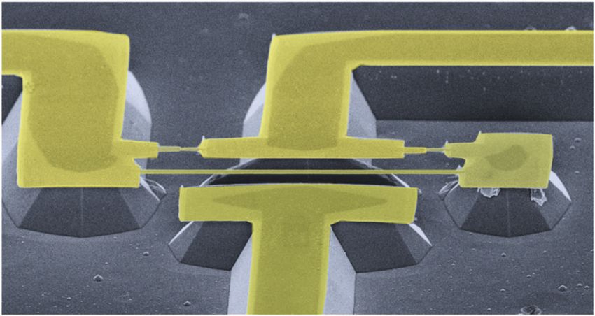
Fig. 2 Measurement of the flux responsivity. a Color scale plot of transmission ∣S21∣ through the cavity as the magnetic flux through the SQUID loop is
varied. The strong qubit–cavity coupling (J) manifests as the avoided crossing, yielding J ~ 2π × 85 MHz. The extension panel shows the trend of avoided
crossing at larger values of the magnetic flux. b The flux-responsivity GΦ± ¼ ∂ω ± =∂Φ, computed using the measured device parameters, assuming identical
junctions, plotted as a function of hybridized frequencies. The black dot denotes the operating point of 6.025 GHz, corresponding to Gþ
Φ =2π 1.8 GHz/Φ0
for the subsequent measurements. The arrow indicates the bare cavity frequency ωc/2π ~ 5.993 GHz. c The flux-responsivity of uncoupled qubit GqΦ ¼
∂ωq =∂Φ with the magnetic flux.
a 6.585 b
VH (a.u.)
−115
Frequency (MHz)
PSD (dBm/Hz)
0.12
6.584 0.08
0.04
−120
6.583
0.00 −125
−20 0 20 −100 −50 0 50 100
Vdc (V) (ω - ω+)/2π (Hz)
c
4
3
g+ /2π (kHz)
2
1
0
0 100 200 300
Φ 0)
Fig. 3 Characterization of mechanical mode and electromechanical coupling rate. a Color plot of the mixed-down signal VH as mechanical actuation
frequency and dc voltage is varied. The mechanical resonance appears as a sharp change in the color. Blue(red) color represents low(high) values of the
signal. To reduce the total measurement time, the mechanical actuation frequency range is automatically adjusted to follow the mechanical mode.
b Average power spectral density (PSD) along with a fitted curve yielding a mechanical linewidth γm ~ 2π × 6 Hz corresponding to a quality factor of ~1.1 ×
106. c Plot of the vacuum electromechanical coupling rate between hybridized mode and the mechanical resonator as the magnetic flux through the SQUID
loop is increased, while ω+ = 2π × 6.025 GHz is kept fixed. The maximum flux applied corresponds to a field of 3.7 mT. The blue-dotted line shows the
expected coupling rate calculated from the device parameters. The error bars represent the uncertainty resulting from the numerical fit of the PSD.
The signal that emerges from the cavity is then mixed-down and mode at ωm ~ 2π × 6.585 MHz with a characteristic capacitive
recorded by a network analyzer. Figure 3a shows the amplitude of frequency softening with Vdc.
the signal in a color plot as the mechanical drive frequency and Next, we focus on the thermal motion of the mechanical
Vdc are varied. The change in color over the background signifies resonator. We operate the hybridized mode at ω+ = 2π × 6.025 GHz
the mechanical resonance. We measure the in-plane vibrational and drive the system with a microwave tone tuned to lower
4 COMMUNICATIONS PHYSICS | (2021)4:12 | https://doi.org/10.1038/s42005-020-00514-y | www.nature.com/commsphysCOMMUNICATIONS PHYSICS | https://doi.org/10.1038/s42005-020-00514-y ARTICLE
sideband (ω+ − ωm), creating a mean photon occupation of ~0.1. a b
The power spectral density (PSD) of the output signal is then Expt. Theory
recorded with a spectrum analyzer. The average PSD, along with the
fitted Lorentzian, is shown in Fig. 3b. We measure a mechanical 2.0 2.0
linewidth of γm = 2π × 6 Hz, corresponding to a quality factor of
~1.1 × 10⁶.
For a drive at the lower sideband, the ratio of integrated power 1.8 1.8
at the up-converted frequency (Pm) near ω+ to the power of
transmitted carrier signal (Pd) at ω+ − ωm can be conveniently
2
normalized |S21|
normalized |S21|
expressed as Pm =Pd ¼ 2g þ =κ nth th
m , where nm is the mean 1.6 1.6
thermal occupation of the mechanical mode, and κ is the
hybridized-mode linewidth. To estimate the thermal occupation
pffiffiffiffiffiffiffiffiffiffiffiffiffiffiffiffiffi 1.4
of the mechanical mode, we first measure ðκ=2Þ ðPm =Pd Þ for 1.4
different values of applied flux. We fit the expected linear
dependence
pffiffiffiffiffiffi of this quantity on magnetic flux to obtain the slope
1.2 1.2
nth
m þðg =ΦÞ. By using the estimated value of g+/Φ from the
device parameters (Eq. (1)), we then obtain the thermal phonon
occupancy of 169. This corresponds to a mode temperature of 1.0 1.0
53 ± 4 mK, which is consistent with the independent estimate
obtained by varying the fridge temperature (additional details are
given in the Supplementary Note 6). Using nth m = 169, we then 0.8 0.8
calculate the g+ as shown in Fig. 3c.
−100 0 100 −100 0 100
We emphasize that the vacuum electromechanical coupling Δqs/2π (MHz) Δqs/2π (MHz)
rate of g+ ~ 2π × 4 kHz is limited by choice of ω+, and the
magnetic field range available in our measurement setup. By Fig. 4 Qubit spectroscopy and Landau–Zener–Stückelberg interference.
operating at ωc ± J, one can achieve the Gþ
q
Φ =GΦ ¼ 1=2, resulting a Measurement of the qubit spectrum with the detuning of spectroscopy
in g+ ~ 2π × 15 kHz. In addition, thin films of Al can withstand a tone Δqs = ωs − ωq, where ωs is the spectroscopy frequency. The
larger magnetic field than the maximum field used here (3.7 mT). mechanical drive signal is varied from 1 to 10 mV in steps of 1 mV (bottom
As the in-plane critical magnetic field is much larger than the to top). The Rabi flop rate ΩR/2π is about 3 MHz. Apart from the primary
perpendicular critical magnetic field for thin Al films, a splitting, weak fringes arising from the Landau–Zener–Stückelberg
configuration with field applied in-plane to the SQUID loop interference are visible. Dotted lines are added as guide to the eye. b The
would result in significantly higher coupling rates for the out-of- solid lines show the results from the Master equation. The dotted lines
plane mechanical mode. show the results from semi-classical calculation. Clearly, the calculations
performed using the Master equation match the experimental results
better. The qubit frequency deviation is changed from 7 MHz to 70 MHz in
LZS interference in the dispersive limit. Next, we investigate the steps of 7 MHz (bottom to top). A qubit relaxation rate of 2 MHz, and a
system by tuning the qubit away from ωc. In the dispersive limit pure dephasing rate of 4 MHz is used to calculate the qubit spectrum. In
∣Δ∣ ≫ J, the mechanics essentially decouples from the cavity mode. both panels, the probe transmission corresponding to the lowest
While the qubit–cavity interaction is given by ðJ 2 =ΔÞ^ay ^aσ^z , the mechanical drive is normalized to one, and an offset of 0.125 has been
longitudinal interaction between the uncoupled qubit and the added successively.
y
mechanical resonator is given by g σ^ ð^b þ ^b Þ, where g ¼
qm z qm
ð∂ωq =∂xÞxzp is the qubit-electromechanical coupling rate and
^bð^by Þ is the lowering (raising) operator for the mechanical mode. almost equal population of the two energy levels. Hence, it results
in the splitting of the qubit spectrum. This splitting of qubit
With a superconducting qubit device, time-dependent long-
spectrum can be captured in semi-classical calculation as shown
itudinal coupling scheme has been used to perform high-fidelity
by the dotted lines in Fig. 4b. Calculation details are included in
qubit measurements34. In the present device, a static gqm would
the Supplementary Note 7.
instead result in a small qubit-state-dependent displacement
At large mechanical drive power, the system crosses avoided-
ð g qm xzp =ωm Þ29. Here, we focus on the qubit dynamics while
crossing region with higher speed. In this regime, one would
driving the mechanical resonator. The qubit is detuned to 4.9 GHz expect to see the interference fringes, arising from multiple
to enhance gqm to 40 kHz, and its spectrum is probed using the Landau–Zener transitions, at a separation close to ωm35. In our
two-tone spectroscopy technique. The mechanical resonator is experiment, as the qubit linewidth is comparable to the
coherently actuated at its resonant frequency. It is equivalent to modulation frequency ωm, the fringes are not well resolved.
the flux-modulation of the qubit frequency at ωm, and a frequency Their signatures are visible as weak modulation between the
deviation set by gqm and the mechanical amplitude. primary splitting. We have performed numerical calculations
Figure 4a shows the qubit spectrum as the strength of based on the Lindblad master equation. The solid line in Fig. 4b
mechanical drive is varied. We observe a splitting in the qubit shows the result from such calculations. Apart from capturing the
spectrum with a weak modulation in-between. The separation linear amplitude dependence of the primary splitting, the
between the primary splitting varies linearly with the mechanical calculated results show the weak modulation in the experimental
amplitude. The primary splitting can be understood by consider- data, whereas the semi-classical calculation only shows the
ing the passage of the system across the region of avoided primary splitting.
crossing with separation set by the strength of the spectroscopic
tone (the Rabi-flop rate ΩR)35. As the system moves across the
avoided crossing at a rate set by ωm, the transition during Conclusion. In summary, we have developed a hybrid electro-
multiple passages mix the two states, eventually resulting in mechanical device by integrating a modified 3D-transmon qubit
COMMUNICATIONS PHYSICS | (2021)4:12 | https://doi.org/10.1038/s42005-020-00514-y | www.nature.com/commsphys 5ARTICLE COMMUNICATIONS PHYSICS | https://doi.org/10.1038/s42005-020-00514-y
and extremely low-loss mechanical resonator of SiN/Al. The 15. Pirkkalainen, J. -M. et al. Cavity optomechanics mediated by a quantum two-
detection of thermo-mechanical motion by driving the system level system. Nat. Commun. 6, 6981 (2015).
with less than one photon highlights the large underlying cou- 16. Viennot, J. J., Ma, X. & Lehnert, K. W. Phonon-number-sensitive
electromechanics. Phys. Rev. Lett. 121, 183601 (2018).
pling rate. Accessibility to different regimes of interaction is 17. Sletten, L. R., Moores, B. A., Viennot, J. J. & Lehnert, K. W. Resolving phonon
further demonstrated by the observation of the LZS interference. fock states in a multimode cavity with a double-slit qubit. Phys. Rev. X 9,
Looking ahead, by accessing in-plane vibration mode through 021056 (2019).
changes in the design geometry and in combination with 18. O’Connell, A. D. et al. Quantum ground state and single-phonon control of a
higher magnetic field, the flux coupling rate can be increased. mechanical resonator. Nature 464, 697–703 (2010).
19. Chu, Y. et al. Creation and control of multi-phonon Fock states in a bulk
With further improvements in the coupling strength, the device acoustic-wave resonator. Nature 563, 666 (2018).
in consideration can reach resolved sideband regime and 20. Arrangoiz-Arriola, P. et al. Resolving the energy levels of a nanomechanical
strong coupling regime. This could enable experiments in the oscillator. Nature 571, 537–540 (2019).
regime of the single-photon cooperativity exceeding one, and 21. Kounalakis, M., Blanter, Y. M. & Steele, G. A. Flux-mediated optomechanics
conditional cooling of the mechanical resonator to the quantum with a transmon qubit in the single-photon ultrastrong-coupling regime. Phys.
Rev. Res. 2, 023335 (2020).
ground state. 22. Koch, J. et al. Charge-insensitive qubit design derived from the Cooper pair
box. Phys. Rev. A 76, 042319 (2007).
Methods 23. Xue, F. et al. Controllable coupling between flux qubit and nanomechanical
Device fabrication and measurement setup. For device fabrication, we use an resonator by magnetic field. New J. Phys. 9, 35–35 (2007).
intrinsic Si (100) substrate coated with a 100-nm-thick high-stress SiN layer grown 24. Nation, P. D., Suh, J. & Blencowe, M. P. Ultrastrong optomechanics
using the low-pressure chemical vapor deposition method. Using standard litho- incorporating the dynamical Casimir effect. Phys. Rev. A 93, 022510 (2016).
graphy and shadow evaporation techniques, the transmon design is patterned in a 25. Khosla, K. E., Vanner, M. R., Ares, N. & Laird, E. A. Displacemon
single lithography step. To release the mechanical resonator, a combination of dry electromechanics: how to detect quantum interference in a nanomechanical
and wet etching processes is used. First, the exposed SiN is vertically etched by the resonator. Phys. Rev. X 8, 021052 (2018).
reactive ion etching using SF6 and CHF3 plasma. The aluminum film naturally acts 26. Etaki, S. et al. Motion detection of a micromechanical resonator embedded in
as a mask layer and thus protects the SiN underneath it. In the second step of a d.c. SQUID. Nat. Phys. 4, 785–788 (2008).
etching, a modified-TMAH-based etchant is used to remove the exposed silicon, 27. Rodrigues, I. C., Bothner, D. & Steele, G. A. Coupling microwave photons to a
while providing excellent selectivity against Al and SiN. Additional details are given mechanical resonator using quantum interference. Nat. Commun. 10, 5359 (2019).
in the Supplementary Note 2. After the wet etch process, the samples are blow- 28. Schmidt, P. et al. Sideband-resolved resonator electromechanics on the single-
dried gently with N2, requiring no critical point drying. The (111)-facets of Si photon level based on a nonlinear Josephson inductance. Commun. Phys. 3,
resulted from the wet etch process can also be seen in Fig. 1d. The sample placed 233 (2020).
inside a copper cavity, along with a small solenoid, is kept inside a cryoperm-shield 29. Didier, N., Bourassa, J. & Blais, A. Fast quantum nondemolition readout by
to protect it from the ambient magnetic field fluctuations. parametric modulation of longitudinal qubit-oscillator interaction. Phys. Rev.
Lett. 115, 203601 (2015).
Data availability 30. Leibfried, D., Blatt, R., Monroe, C. & Wineland, D. Quantum dynamics of
All raw data and processed data as well as supporting code for processing and single trapped ions. Rev. Mod. Phys. 75, 281–324 (2003).
figure generation are available in Zenodo with the DOI: https://doi.org/10.5281/ 31. Barends, R. et al. Coherent Josephson qubit suitable for scalable quantum
zenodo.4314415. integrated circuits. Phys. Rev. Lett. 111, 080502 (2013).
32. Ludwig, M., Safavi-Naeini, A. H., Painter, O. & Marquardt, F. Enhanced
quantum nonlinearities in a two-mode optomechanical system. Phys. Rev.
Received: 21 October 2020; Accepted: 16 December 2020; Lett. 109, 063601 (2012).
33. Bishop, L. S. et al. Nonlinear response of the vacuum Rabi resonance. Nat.
Phys. 5, 105–109 (2009).
34. Touzard, S. et al. Gated conditional displacement readout of superconducting
qubits. Phys. Rev. Lett. 122, 080502 (2019).
35. Shevchenko, S. N., Ashhab, S. & Nori, F. Landau-Zener-Stückelberg
References interferometry. Phys. Rep. 492, 1–30 (2010).
1. Aspelmeyer, M., Kippenberg, T. J. & Marquardt, F. Cavity optomechanics.
Rev. Mod. Phys. 86, 1391–1452 (2014).
2. Teufel, J. D. et al. Sideband cooling of micromechanical motion to the Acknowledgements
V.S. acknowledges the support received from Infosys Science Foundation, and under the
quantum ground state. Nature 475, 359–363 (2011).
“Early Career Research Award” by SERB, Department of Science and Technology (DST),
3. Chan, J. et al. Laser cooling of a nanomechanical oscillator into its quantum
Govt. of India. T.B. and S.M. thank Tata Trust for providing the travel support. The
ground state. Nature 478, 89–92 (2011).
authors acknowledge device fabrication facilities at CeNSE, IISc, Bangalore, and central
4. Anetsberger, G. et al. Measuring nanomechanical motion with an imprecision
facilities at the Department of Physics funded by DST. Authors thank R. Vijayraghavan,
below the standard quantum limit. Phys. Rev. A 2, 061804 (2010).
Manas Kulkarni, Diptiman Sen, and G. S. Agarwal for valuable discussions.
5. Pirkkalainen, J.-M., Damskägg, E., Brandt, M., Massel, F. & Sillanpää, M. A.
Squeezing of quantum noise of motion in a micromechanical resonator. Phys.
Rev. Lett. 115, 243601 (2015). Author contributions
6. Wollman, E. E. et al. Quantum squeezing of motion in a mechanical resonator. T.B. and S.M. contributed equally to this work. V.S. conceived the experiments. T.B. and
Science 349, 952–955 (2015). S.M. fabricated the devices. T.B., S.M., and S.K.S. performed the measurements. T.B.,
7. Peterson, G. A. et al. Demonstration of efficient nonreciprocity in a microwave S.M., and V.S. performed the data analysis. All the authors contributed to writing of the
optomechanical circuit. Phys. Rev. X 7, 031001 (2017). manuscript and discussing the results.
8. Bernier, N. R. et al. Nonreciprocal reconfigurable microwave optomechanical
circuit. Nat. Commun. 8, 604 (2017).
9. Barzanjeh, S. et al. Mechanical on-chip microwave circulator. Nat. Commun. Competing interests
8, 1–7 (2017). The authors declare no competing interests.
10. Riedinger, R. et al. Remote quantum entanglement between two
micromechanical oscillators. Nature 556, 473–477 (2018). Additional information
11. Ockeloen-Korppi, C. F. et al. Stabilized entanglement of massive mechanical Supplementary information is available for this paper at https://doi.org/10.1038/s42005-
oscillators. Nature 556, 478–482 (2018). 020-00514-y.
12. Reed, A. P. et al. Faithful conversion of propagating quantum information to
mechanical motion. Nat. Phys. 13, 1163–1167 (2017). Correspondence and requests for materials should be addressed to V.S.
13. Lecocq, F., Teufel, J. D., Aumentado, J. & Simmonds, R. W. Resolving the
vacuum fluctuations of an optomechanical system using an artificial atom. Reprints and permission information is available at http://www.nature.com/reprints
Nat. Phys. 11, 635–639 (2015).
14. Pirkkalainen, J.-M. et al. Hybrid circuit cavity quantum electrodynamics with Publisher’s note Springer Nature remains neutral with regard to jurisdictional claims in
a micromechanical resonator. Nature 494, 211–215 (2013). published maps and institutional affiliations.
6 COMMUNICATIONS PHYSICS | (2021)4:12 | https://doi.org/10.1038/s42005-020-00514-y | www.nature.com/commsphysCOMMUNICATIONS PHYSICS | https://doi.org/10.1038/s42005-020-00514-y ARTICLE
Open Access This article is licensed under a Creative Commons
Attribution 4.0 International License, which permits use, sharing,
adaptation, distribution and reproduction in any medium or format, as long as you give
appropriate credit to the original author(s) and the source, provide a link to the Creative
Commons license, and indicate if changes were made. The images or other third party
material in this article are included in the article’s Creative Commons license, unless
indicated otherwise in a credit line to the material. If material is not included in the
article’s Creative Commons license and your intended use is not permitted by statutory
regulation or exceeds the permitted use, you will need to obtain permission directly from
the copyright holder. To view a copy of this license, visit http://creativecommons.org/
licenses/by/4.0/.
© The Author(s) 2021
COMMUNICATIONS PHYSICS | (2021)4:12 | https://doi.org/10.1038/s42005-020-00514-y | www.nature.com/commsphys 7You can also read