Metamaterial array based meander line planar antenna for cube satellite communication
←
→
Page content transcription
If your browser does not render page correctly, please read the page content below
www.nature.com/scientificreports
OPEN Metamaterial array based meander
line planar antenna for cube
satellite communication
Touhidul Alam1*, Ali F. Almutairi2*, Md Samsuzzaman3, Mengu Cho4 &
Mohammad Tariqul Islam5*
This research article presents a design and performance analysis of a metamaterial inspired ultra-high
frequency (UHF) compact planar patch antenna for the CubeSat communication system that could be
smoothly integrated with commercially available 2U Cube Satellite structure and onboard subsystem.
The proposed antenna consists of two layers, one is two different width meander line antenna
patch with partial ground plane and another layer is 3 × 2 near-zero-indexed metamaterial (NZIM)
metamaterial array structure with ground plane. The NZIM array layer has been utilized to minimize
the coupling effect with Cube Satellite structure and improve the frequency stability with enhanced
antenna gain and efficiency. The fabricated antenna can operate within the lower UHF frequency band
of 443.5–455 MHz. with an average peak gain of 2.5 dB. The designed antenna impedance stability
characteristic has been explored after integration with the 2U Cube Satellite body layout. Besides, the
antenna communication performance has been verified using 2U Cube Satellite free space path loss
investigation. Small antenna volume with trade-off between the antenna size and performance are
the key advantages of the proposed design, as the antenna occupies only 80 × 40 × 3.35 mm3 space of
the 2U Cube Satellite body structure and the geometrical parameters can be designed to provide the
best performance between 449 and 468.5 MHz.
Cube satellite missions have increased dramatically in both research and commercial sectors due to economic
affordability and short building period. Cube satellites are tiny cube-shaped small satellites with Unit (U) dimen-
sions of 10 × 10 × 10 cm3 and a mass less than 1.33 kg per U. The cubic structure encompasses an enclosed
aluminum box with solar cells fitted to the outside walls. The antenna is a crucial element of the satellite com-
munication system. The development of a low profile with efficient antenna performance is highly desirable
for the Cube Satellite communication system. However, inherently inverse proportionality between antenna
performance and size is the big challenge to design Cube satellite antenna. Maintaining good performance with
specific Cube satellite requirements represent a major mechanical and RF challenge. Mutual coupling between
the antenna and other components that can degrade antenna performances is one of the key challenges of the
small satellite antenna. Over the last decade, several types of antennas have been developed for the small satellite
communication system, which can be summarized in two categories: deployable antenna and non-deployable
antenna. Both types of antennas have been developed by considering the size and weight of the Cube satellite,
which are the most vital factors that have a profound influence on antenna type and design1.
Wire antennas are widely used a deployable antenna in small satellites at high frequency (HF), VHF, and
UHF applications. Monopole, dipoles, Yagi-Uda arrays and helical antennas are different types of wire antennas,
which are typically placed on the outer face of the small satellite structure to facilitate space for other electronic
components. The adverse fact of this type of antenna is that they require different deployment mechanism. But
the mechanical deployment of this type of antenna is stimulating, and which might be increased the chance of
mission failure2, 3. In contrast to the deployable antenna, non-deployable antennas like, patch antennas provide
a modest solution to this issue with better mission reliability. However, this type of antenna has a frequency
shifting issue due to a non-infinite ground plane and the effect of a metallic satellite body. Planar antennas
1
Space Science Centre (ANGKASA), Institute of Climate Change (IPI), Universiti Kebangsaan Malaysia, 43600 Bangi,
Selangor, Malaysia. 2Electrical Engineering Department, Kuwait University, 13060 Kuwait, Kuwait. 3Department
of Computer and Communication Engineering, Faculty of Computer Science and Engineering, Patuakhali Science
and Technology University, Dhaka, Bangladesh. 4Laboratory of Spacecraft Environment Interaction Engineering
(LaSEINE), Kyushu Institute of Technology, Fukuoka 804‑8550, Japan. 5Department of Electrical, Electronic
and Systems Engineering, Faculty of Engineering and Built Environment, Universiti Kebangsaan Malaysia,
43600 Bangi, Selangor, Malaysia. *email: touhidul@ukm.edu.my; ali.almut@ku.edu.kw; tariqul@ukm.edu.my
Scientific Reports | (2021) 11:14087 | https://doi.org/10.1038/s41598-021-93537-6 1
Vol.:(0123456789)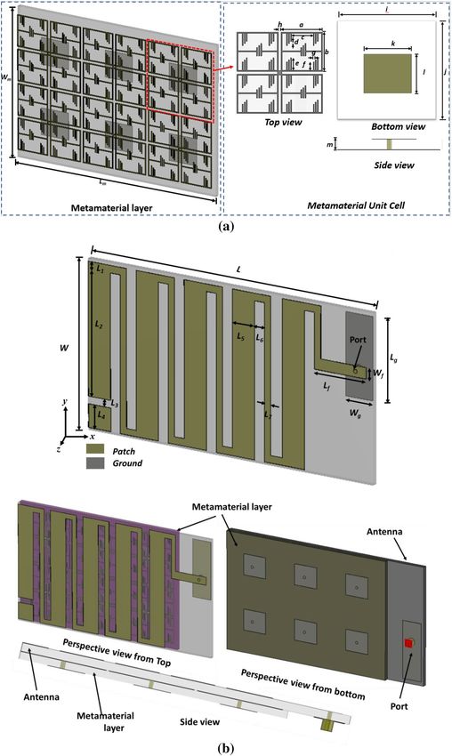
www.nature.com/scientificreports/
have gain special attention for the small satellite communication system, owing to their low profile and ease of
fabrication4–6. However, the size of the lower UHF antenna becomes larger in size, which grabs a large volume of
the CubeSat body surface and makes them difficult to place adequate solar cells. To address these issues, the high
dielectric substrate (εr = 10.2) based patch antenna has been developed for the USUSAT nanosatellite mission7.
The antenna was developed for 450 MHz uplink data of Ionospheric Observation Nanosat Formation (ION-F)
constellation. After that, lots of patch antennas have been studied for the nanosatellite communication s ystem8, 9.
In10, a UHF 433 MHz printed patch antenna has been developed, which was printed on 51 mm × 28 mm FR-4
substrate material. But the major drawback of this design was low gain, only − 13 dB. Meander line technique
expedites to achieve the lower band with miniature antenna d imension11. Nevertheless, the performance of these
types of antenna degrades when fixed with the complex structure and circuitry. To enhance antenna gain and
efficiency, the antenna size needs to enhance. Several antennas have been designed using the meander line struc-
ture for the UHF communication system of various nanosatellite applications, LAPAN-TUBSAT microsatellite
is one of them. A meander line structured antenna has been developed for telemetry and telecommand applica-
tions of LAPAN-TUBSAT, was operated at 428–468 MHz. The antenna achieved 2.9 dBi gain with dimensions
of 160 × 140 mm212. In recent years, metamaterial inspired antenna concept has been utilized to miniaturize
antenna size with maintaining effective and optimal p erformances13. So far, these metamaterial antenna designs
have been performed using negative permeability, negative permittivity or double negative (DNG) metamaterial,
which is used to miniaturize the antenna size due to their quasi-static resonant response14. Besides, another type
of metamaterial has been developed to support near-infinite phase velocity and “static-like” field distributions
as well as equally fascinating wave propagation properties15. Recently, near-zero index metamaterial loaded 400
MHz UHF antenna for nanosatellite communication system was p resented6. The proposed antenna was consisted
of a same width meander line patch and metamaterial inspired partial ground, where metamaterial structures
were placed on the same plane of the ground plane. But this antenna suffers lower efficiency and lower gain.
Moreover, antenna operating frequency tuning is quite difficult and do not have direct operating frequency tun-
ing relation with a single antenna parameter. Therefore, our goal is to design an UHF antenna that can enhance
antenna efficiency and gain with compact antenna dimension to reduce the risk of CubeSat mission failure in
space environment.
In this paper, a lower UHF meander line antenna is designed using a near-zero metamaterial. To verify the
antenna performance, the antenna has been fabricated, and the antenna’s performance has been investigated.
The fabricated antenna can operate within the lower UHF frequency band of 443.5–455 MHz. with an average
peak gain of 2.5 dB. The designed antenna impedance stability characteristic has been explored after integration
with the 2U Cube Satellite body layout. Moreover, the antenna communication performance has been verified
using 2U (20 × 10 × 10 cm3) Cube Satellite free space path loss investigation.
Antenna geometric layout configuration
The antenna design structure of the optimized antenna and NZIM metamaterial structures are shown in Fig. 1.
The proposed antenna simulation is performed by 3D electromagnetic simulator CST (Computer System Tech-
nology) microwave studio suite, 2 01916. The antenna consists of a modified meander line patch in the top and
partial ground plane on the other side of the substrate. A metamaterial layer with a 3 × 2 near-zero index meta-
material (NZIM) array is placed under the antenna, where the metamaterial structure consists of thin metallic
arms and split ring resonant (SRRs) with the rectangular ground plane, which is shown in Fig. 1b. The patch
antenna and metamaterial layer are designed on low loss space compatible Rogers Duroid 5880 substrate mate-
rial with a height of 1.575 mm. The size of the metamaterial layer is 65 × 40 × 1.575 mm3. The overall optimized
dimension of the antenna is 80 × 40 × 3.35 mm3. The initial partial grounded meander line antenna structure was
designed considering conventional monopole and printed dipole mechanism and then, modified the structure to
partial grounded meander line. The antenna size was chosen considering on CubeSat size constrain, conventional
monopole size for 450 MHz, which is 166.5 mm × 66 mm × 1.57 mm and the size of 0.5λ printed dipole format
(333.11 mm). The antenna structured was modified using fold the conductors back and forth mechanism to
minimize the length of 80 × 40 × 1.57 m m3. Though the antenna size becomes smaller, the antenna bandwidth
and radiation efficiency also decrease. As the width of the meander, line contributes to the capacitance associated
with the ground plane, so the resonance frequency of the meander-lined antenna can be controlled by changing
the width of the meander lines. Moreover, effective self-inductance can be modified by increasing the meander
line section and thus, the lower frequency can be adjusted. The antenna size in the proposed design can be
minimized by appropriate optimization of a number of folds, inter folds distance and line width. A 50-Ω coaxial
direct feed is used for connecting the patch and ground plane for excitation which location is identified in the
design layout in Fig. 1b. Checking the 50-Ω impedance matching initially, we have chosen the location on the
right side of the meander line-starting patch and check the input impedance and surface current through the
CST simulator. By tuning the position of the feed location and feed line length of 14.38 mm, we have achieved
the 50-Ω impedance for the proposed antenna. The antenna is fed by a 50Ω Micro-miniature coaxial (MMCX)
connector. A slot L3 has been etched from the upper arm of the meander line to tune the resonating frequency.
The design evolution of the proposed antenna is illustrated with reflection coefficient, shown in Fig. 2, where
shows that the metamaterial array embedded antenna resonates at 450 MHz. To enhance antenna radiation per-
formance, single metamaterial unit cell was placed behind ground layer of the antenna, which shifted resonating
frequency downwards. To tune the antenna from 580 MHz frequency to 450 MHz, L 3 slit was etched from the
meander line structure. After that different array configuration was investigated to achieve resonant frequency
at 450 MHz with optimum radiation performances, shown in Fig. 2a. Figure 2b also illustrates the input imped-
ance curve of the proposed antenna. From this figure it can stated that, the real and imaginary (reactance)
input impedance value of the proposed antenna at 450 GHz are about 50 Ω and zero, respectively. Moreover,
Scientific Reports | (2021) 11:14087 | https://doi.org/10.1038/s41598-021-93537-6 2
Vol:.(1234567890)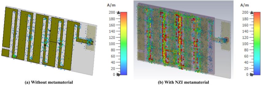
www.nature.com/scientificreports/
Figure 1. (a) NZIM Metamaterial layout configuration and (b) design layout of the optimized antenna. (CST
STUDIO SUITE 2019, https://www.3ds.com/products-services/simulia/products/cst-studio-suite)16.
Scientific Reports | (2021) 11:14087 | https://doi.org/10.1038/s41598-021-93537-6 3
Vol.:(0123456789)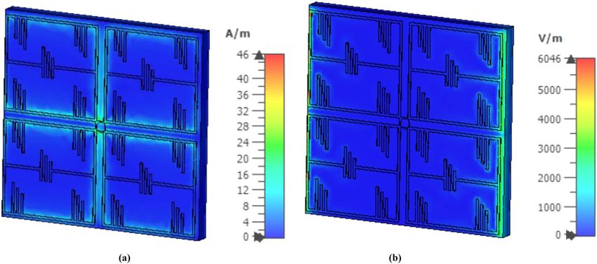
www.nature.com/scientificreports/
Figure 2. (a) Antenna reflection coefficient ( S11) at various stages of the proposed design, (b) input impedance
curve of the proposed antenna.
Figure 3. (a) Antenna reflection coefficient for various length of L2 and (b) realized gain and efficiency for
different values of L2.
the resonating frequency can be controlled by shifting the L2 slot position, depicted in Fig. 3. It is shown from
Fig. 3a that when the slot moves upward, the L2 value decreases and the L4 value increases. The resonant frequency
moves to the upper frequency by decreasing the L2 value. The optimized antenna can be tuned by changing the
length of the dimension L2. The normalized Equation for the frequency tuning is proposed based on the critical
parameter of L2, depicted in Eq. (1)
f (L2 ) = 467 − 0.46L2 (1)
The antenna can be tuned from 449 to 468 MHz by adjusting the length of the L2 value. The realized gain
and total efficiency remain near constant. The final design dimension parameters of the proposed antenna are
depicted in Table 1.
The metamaterial unit cell layout has been designed, simulated, and investigated using 3D electromagnetic
CST microwave studio simulation software. According t o17, a perfect electric conductor (PEC) in the X-direction
and a perfect magnetic conductor (PMC) in the Y-direction has been set as a boundary condition to simulate
the metamaterial unit cell structure. Throughout the Z-direction, the electromagnetic wave is propagated. By
using the robust methods, the metamaterial unit cell characteristics of permittivity, permeability and refractive
index have been investigated after extracting the S parameter from the simulation environment18, 19. The unit
cell initial dimension has been taken based on the general subwavelength rules as λ/2020. Since our target was
to design a UHF band 450 MHz metamaterial unit cell, according to the λ/20 relationship, the main dimen-
sion of the metamaterial unit cell has taken initially 33 mm. For miniaturization of the unit cell dimension, we
have scaled the dimension in CST and introduce some split gap in the unit cell structure, which is described in
Fig. 1a. Finally, we have achieved the 22 mm length and width of the split ring resonator of the main unit cell
length to achieve. The metamaterial structure depicts near zero permeability (− 0.109), permittivity (0.003) at
Scientific Reports | (2021) 11:14087 | https://doi.org/10.1038/s41598-021-93537-6 4
Vol:.(1234567890)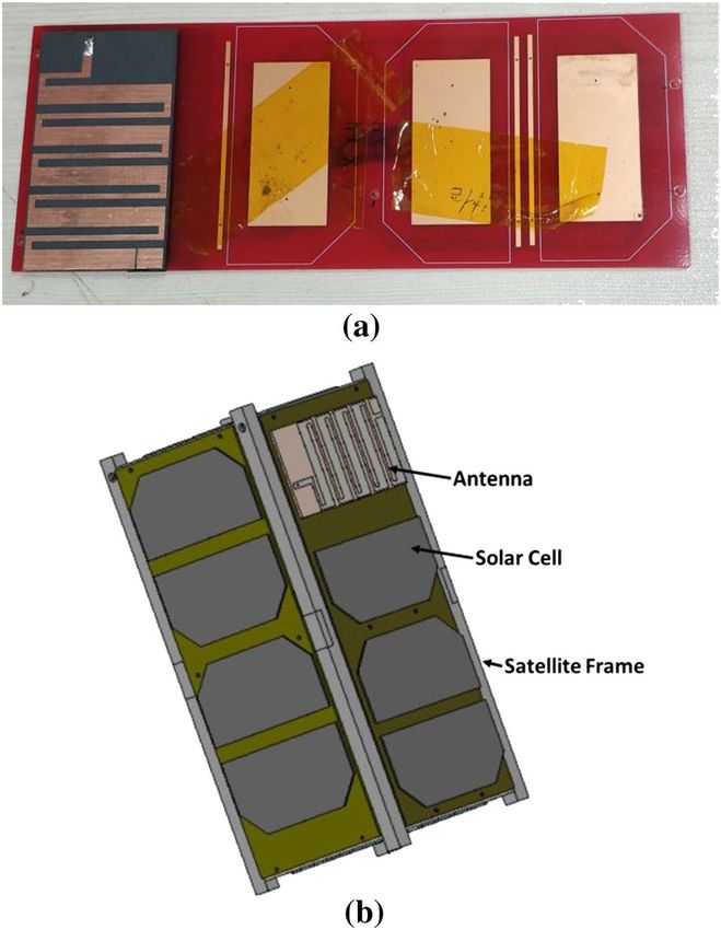
www.nature.com/scientificreports/

                                   Design parameters   Value (mm)   Design parameters   Value (mm)
                                   L                   80           Wf                  3
                                   L1                  2            a                   10
                                   L2                  33.5         b                   9.5
                                   L3                  2            c                   5.25
                                   L4                  6.18         d                   0.5
                                   L5                  6.3          e                   3
                                   L6                  2.72         f                   2
                                   L7                  1.8          g                   0.25
                                   Lf                  14.38        l                   22
                                   Wm                  45           Lm                  65
                                   W                   45           m                   1.575
                                   i                   21.2         j                   20
                                   k                   9            l                   8

                                  Table 1.  Optimized design dimension of the finalized antenna.

                                  Figure 4.  Retrieved metamaterial characteristics for the metamaterial unit cell (a) permittivity, (b)
                                  permeability, and (c) refractive index.

                                  450 MHz, shown in Fig. 4. Besides, it is shown from Fig. 4 that the real value of the near-zero (NZ) permeabil-
                                  ity of the unit cell structure show from 400 to 540 MHz, NZ permittivity shows from 433 to 600 MHz and the
                                  near-zero refractive index shows in the entire operating bandwidth. The H-field and E-field distribution of the
                                  designed metamaterial has been examined, which is revealed in Fig. 5. It can be observed from Fig. 5 that the
                                  effective epsilon (ε) is achieved towards near-zero (ENZ) with the help of outer metallic arms, whereas effective

Scientific Reports |   (2021) 11:14087 |                https://doi.org/10.1038/s41598-021-93537-6                                               5

                                                                                                                                            Vol.:(0123456789)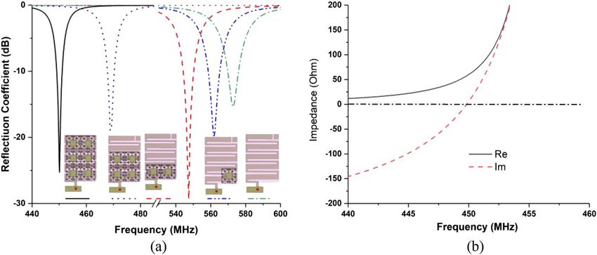
www.nature.com/scientificreports/
Figure 5. Simulated (a) H-field and (b) E-field distribution of the designed metamaterial unit cell at 450 MHz
(CST STUDIO SUITE 2019, https://www.3ds.com/products-services/simulia/products/cst-studio-suite)16.
Z Printed Antenna
z
Only Printed Antenna H
Y
NZIM
E
Y H
k
H k
E Metamaterial Layer
E k
(a) (b)
Figure 6. (a) Only antenna, (b) antenna with EMNZ metamaterial layer.
μ near-zero (MNZ) is obtained due to the magnetic resonance experienced by split-ring resonators due to their
interconnection. Therefore, the structure can attain impedance-matched near-zero-index metamaterial (NZIM)
characteristics with both ENZ and MNZ properties.
The antenna performance enhancement mechanism of the proposed UHF antenna using NZI metamaterial
can be explained through Fig. 6a,b. When the sideward electromagnetic wave (EM) wave is incident to the NZRI
layer, the sideward radiation power possesses the electromagnetic field E component perpendicular to the cover
(along the Z-axis). Due to the mechanism of NZI metamaterial that EM waves are emitted from the NZI layer
along the regular direction of the interfaces, some sideward EM waves are parallel to the XY plane after passing
through the metamaterial cover. For that reason, the increased EM waves are parallel to the UHF planar antennas
horizontal plane, changes the direction of the main beam of the antenna so that the antenna performance like gain
and efficiency are increased. Besides, the antenna performance mechanism with and without NZI metamaterial
is also investigated by using the surface current analysis which is shown in Fig. 7. It can be observed that after
NZI metamaterial incorporation, a strong current is developed near meander line. It can be predicted that the
NZI structure has driven the surface current and act as vital radiation elements. Hence, the meander line with
metamaterial radiated stronger radiation fields than without a metamaterial antenna and contribute to improving
the radiation efficiency and gain of the antenna.
Experimental results and discussion
The final design parameters enlisted in Table 1 have been used for the fabrication of the antenna prototype in a
lab environment. The numerical and measured reflection coefficient ( S11) has been measured in free space, which
is shown in Fig. 8. The antenna achieved resonance at 450 MHz in simulation. In measurement, the resonance
remains the same position, but the impedance bandwidth increased, which is 443.5–455 MHz. The possible
reasons for discrepancy between simulated and measured results is fabrication tolerance and feeding tolerance.
Moreover, copper etching, high temperature soldering may have effect on substrate material properties. Besides,
as the antenna is fed by a 50 Ω micro-miniature coaxial (MMCX) connector. Therefore, another extension cable
and converter are required to connect the antenna with VNA. This extension cable losses during measurement
might be another possible reason. These issues were not considered in simulations environment. The antenna
performance has also been investigated with a 2U cube satellite body structure, which is shown in Fig. 9. The
Scientific Reports | (2021) 11:14087 | https://doi.org/10.1038/s41598-021-93537-6 6
Vol:.(1234567890)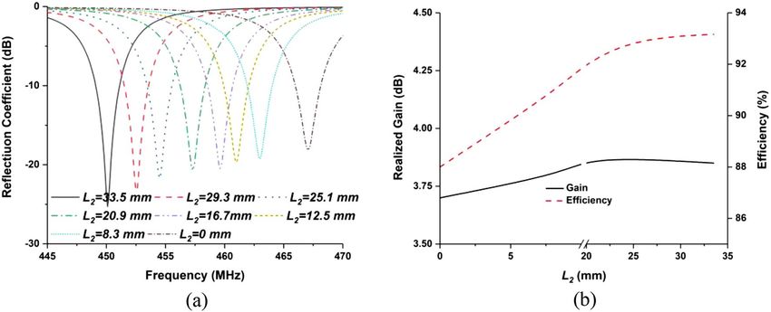
www.nature.com/scientificreports/
Figure 7. Surface current distribution of the proposed antenna (CST STUDIO SUITE 2019, https://www.3ds.
com/products-services/simulia/products/cst-studio-suite)16.
Figure 8. The numerical and experimental reflection coefficient of the optimized antenna.
measured reflection coefficient has been examined while the antenna is mounted on the 2U Cube satellite struc-
ture, depicted in Fig. 10. In measurement, the antenna resonance slightly shifted downwards and tuned at 450
MHz, and the antenna shows − 10 dB impedance bandwidth shows from 435.5 to 461 MHz. The peak resonance
in simulated and measured results are identical, though a mismatch is observed. In measurement the antenna
performance has been investigated using live 2U CubeSat structure. The structure was considered as 227 mm
tall in Z axis, 100 mm length in X and Y axes with maximum weight was 2.6 kg. Aluminium 7075 material was
considered for the nanosatellite frame structure. The proposed antenna and solar panels have been mounted
on the FR-4 backplane oard using RTV glue (Room-Temperature-Vulcanizing glue). The structure has a single
motherboard, which is placed inside the structure. Moreover, several subsystem and parts like battery, font
panel, transmitter and communication board, payload circuitry etc. have been considered as in its real proper-
ties. A dummy mass made of Aluminium 7075 substrate was placed at the middle of the structure to balance the
structure. However, in simulation only the outer structure and backplane with solar panel were considered to
examine the antenna performances. These factors may be the possible reasons for the discrepancy in simulation
and measurement results. The 2D radiation characteristics of the fabricated antenna with the 2U Cube satellite
structure have also been examined using the Satimo Starlab Nearfield Measurement System21. The StarLab is
capable of measuring frequency from 350 MHz to 6 GHz. The baseline configuration is obtained by connecting
StarLab to a Vector Network Analyzer (VNA) for passive antenna measurements. The simulated and measured 2D
radiation patterns of the antenna with Cube satellite structure are found to be in good agreement in H-plane and
maintained approximate omnidirectional radiation pattern, presented in Fig. 11. However, the cross-polarization
value has been increased in measurement, and that might occur due to the presence of the metallic structure.
Similarly, the E-plane radiation pattern shows little disagreement in measurement. The radiation efficiency and
Scientific Reports | (2021) 11:14087 | https://doi.org/10.1038/s41598-021-93537-6 7
Vol.:(0123456789)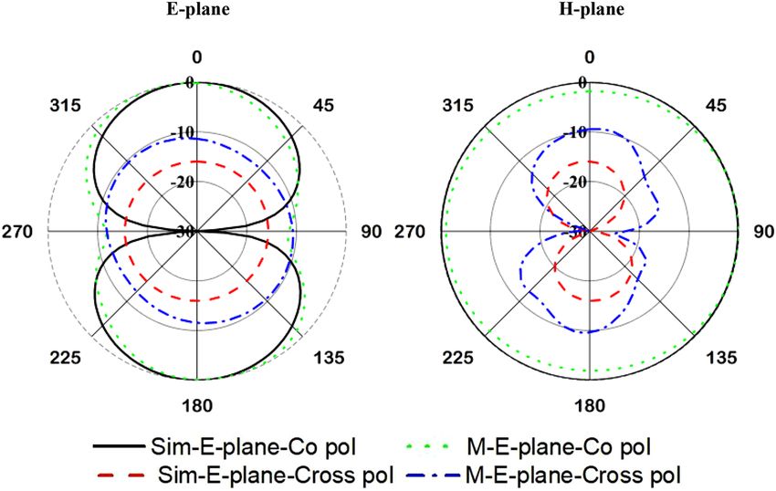
www.nature.com/scientificreports/
Figure 9. Optimized antenna mounted on 2U Cube satellite body in (a) fabricated structure and (b) simulation
environment.
Figure 10. Reflection coefficient (S11) of the optimized antenna with 2U Cube Satellite.
Scientific Reports | (2021) 11:14087 | https://doi.org/10.1038/s41598-021-93537-6 8
Vol:.(1234567890)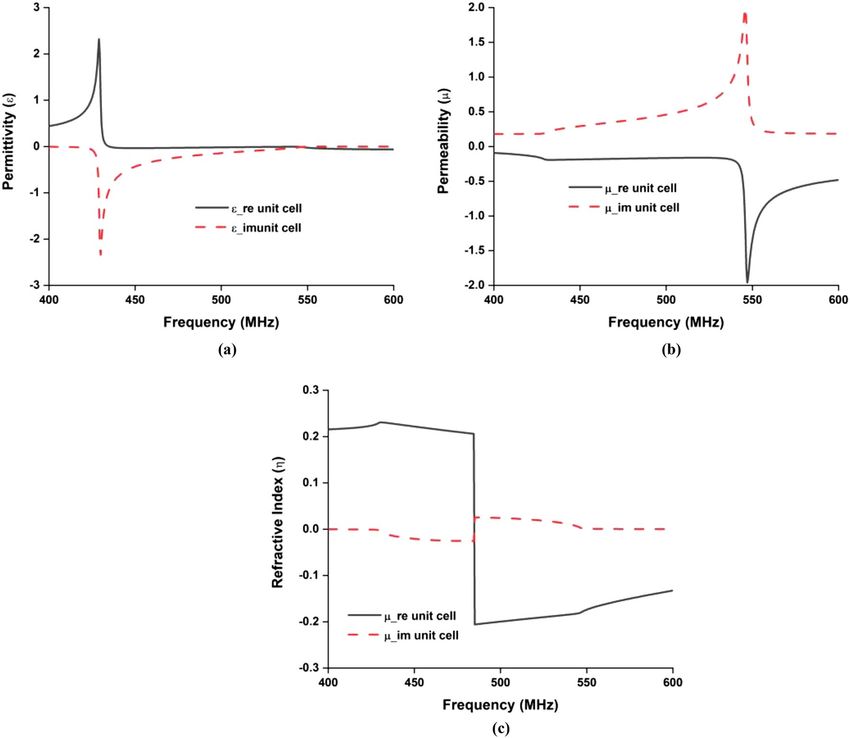
www.nature.com/scientificreports/
Figure 11. Simulated and measured 2D radiation patterns of the proposed antenna mounted on Cube satellite
backplane at 450 MHz.
gain of the antenna while integrated with Cube satellite body structure have also been analyzed. The antenna
obtained 69% radiation efficiency and gain of 2.5 dB with the Cube satellite structure.
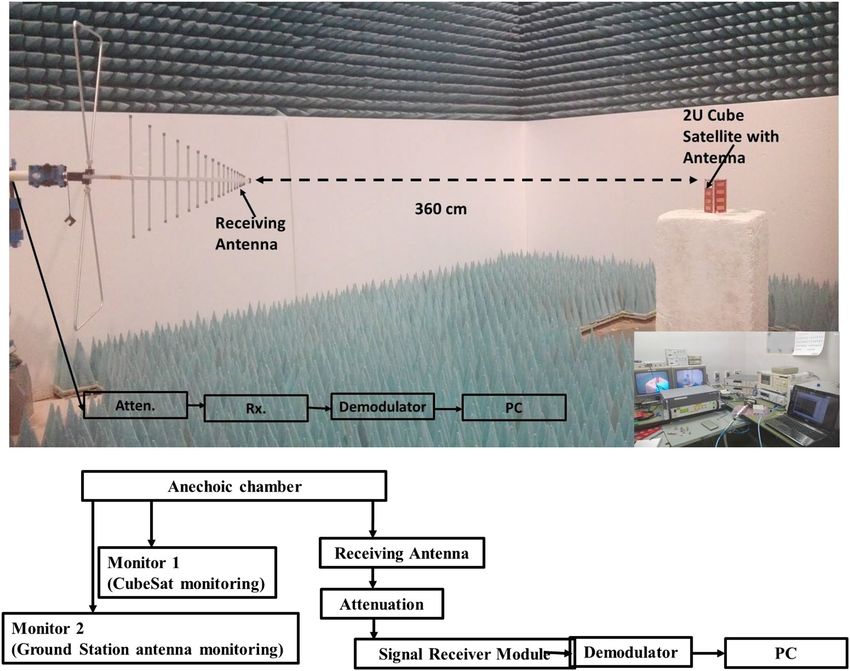
The assessment of signal propagation with maximum value for the proposed antenna is accomplished by
conducting free space path loss (FSPL) calculation using variable attenuation. The measurement was performed
in the Laboratory of Spacecraft Environment Interaction Engineering (LaSEINE), Kyushu Institute of Technology,
Japan. To perform this estimation antenna is incorporated with an active Cube Satellite. LEO orbit at a distance of
400 km from the ground is considered for the calculation purpose of FSPL. Friis transmission equation has been
employed for this calculation22. The antenna has been tuned at 467 MHz and mounted on a 2U Cube Satellite
structure due to measurement limitations that can only measure FSPL at 467 MHz. Active communication board
has been integrated into the satellite and connected with the proposed antenna. The antenna is functioned as the
transmitting antenna (Tx). The measurement setup is illustrated in Fig. 12. The receiving antenna (Rx) is placed
in the horizontal orientation and connected to the receiver module through a variable attenuator. The transmit-
ted signal from the satellite through proposed antenna has been demodulated and investigated the maximum
level of attenuation until the smooth demodulation is possible. The maximum level of attenuation represents the
signal strength of the transmitter antenna, which can address the maximum path loss.
The free space path loss in an anechoic chamber (FSPL) = 36.95 dB.
The FSPL at an orbital altitude of 400 m = 137.9 dB.
The log periodic antenna gain ( GRx) = 6.9 dBi.
The ground station antenna gain (G′Rx) = 18 dBi.
The extra attenuation is required to achieve signal level = Orbital FSPL – FSPL − G′Rx + GRx = 89.85 dB.
It is seen from Table 2 that the proposed antenna facilities 9 dB extra attenuation for signal demodulation.
A comparison between the proposed UHF cube satellite antenna, commercial antennas and some other
existing small satellite antenna papers are given in Table 3. This comparison’s main parameters are antenna
dimension (mm), antenna type, operating frequency (MHz), realized gain (dBi), cube satellite compatibility
and remarkable comments where the proposed antenna performances are better than compared r esearch6, 23–33
based on various parameters. From Table 3, it is seen that the proposed antenna provides a significant trade-off
between the antenna size and performance in terms of operating frequency, gain, and efficiency for successful
CubeSat payload mission. Moreover, the antenna gain integrated with Cube satellite structure is satisfactory for
smooth uplink and downlink communication, which is verified in FSFL measurement in Fig. 12. Based on the
comparison and CubeSat antenna design constraints, the proposed antenna has achieved potentiality for smooth
CubeSat payload operation.
Conclusion
This research article described the design, simulation, and measurement of a UHF NZI metamaterial antenna
for the CubeSatellite communication system. The numerical results are in good agreement with the measure-
ment results. The advantages of the optimized metamaterial loaded antenna are wide impedance bandwidth
Scientific Reports | (2021) 11:14087 | https://doi.org/10.1038/s41598-021-93537-6 9
Vol.:(0123456789)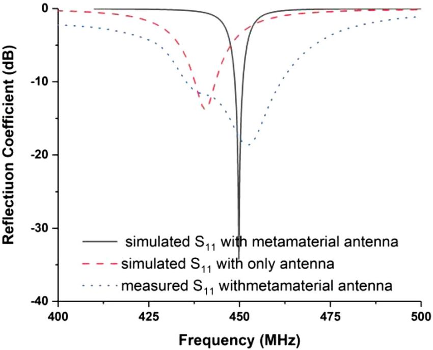
www.nature.com/scientificreports/

                                            Figure 12.  FSPL estimation in the anechoic chamber and maximum attenuation measurement until signal
                                            demodulation.

                                             Cube satellite rotation (angle, degree)   Max. attenuation value (dB)
                                             0                                         98
                                             20                                        104.5
                                             80                                        98
                                             100                                       98
                                             180                                       99
                                             200                                       98
                                             280                                       98
                                             300                                       98

                                            Table 2.  Achieved maximum attenuation to address the maximum FSPL.

                                            with stable gain, compact dimension, easy fabrication, and flexibility in designing antenna at desired frequency
                                            with optimized the geometrical parameters. The assessment of signal propagation with maximum value for the
                                            proposed antenna is accomplished by conducting FSPL calculation using variable attenuation, successfully. In
                                            this regard, the proposed NZIM metamaterial embedded compact UHF printed antenna have the potential to
                                            be used in LEO orbit Cube Satellite for command function, tracking and data downlink applications.

          Scientific Reports |   (2021) 11:14087 |                   https://doi.org/10.1038/s41598-021-93537-6                                          10

Vol:.(1234567890)
www.nature.com/scientificreports/
Antenna dimension Operating frequency Cube satellite
Existing research (mm) Antenna type (MHz) Realized gain (dBi) compatibility Comments
Planar Patch
6 Low gain and low
80 × 45 × 1.575 Antenna Printed EMNZ 391–405 1.77 Compatible
efficiency
metamaterial
23
320 × 80 × 3.17 Printed Antenna 427–437 2.12 Incompatible Larger dimension
Low gain and operating
24, 25
72 × 32 × 1.575 Planar Patch Antenna 418–448 0.55 Compatible frequency shifted after
mount in body
26 Larger dimension and
170 × 120 × 6.4 Microstrip Patch 435–437 0.7 Incompatible
low gain
27 Larger dimension and
150 × 150 × 37 Microstrip Patch 384–410 0.4 Incompatible
low gain
Antenna performance
28
Height :500 Deployable helix 365 8 Incompatible high but incompatible
with 1U CubeSat
29
175 Deployable monopole 435–440 0.08 Compatible Low efficiency
30 circumference of a 1.5U cavity backed slot
485 MHz 2.73 dB Compatible –
CubeSat 100 × 100 × 150 antenna
31
92 × 40 Planar patch 435 MHz -1 dB Compatible 55%
32
85 × 85 × 31 Inverted-F antenna 400 MHz 5.37 Compatible –
33
100 × 100 × 9.4 Stack antenna 2025–2290 MHz 7.4 Compatible 70–96%
98 × 98 × 7 mm3 Envelope
34, 35
stowed Deployable monopole 435–438 MHz 0 Compatible –
170 mm length
Planar patch antenna 69% with realized gain
Proposed design 80 × 40 × 3.35 with embedded NZIM 443.5–455 2.5 Compatible of 2.5 dB at operating
layer frequency
Table 3. A comparison of the proposed MTM loaded Patch antenna with existing UHF cube satellite
antennas.
Received: 16 April 2021; Accepted: 28 June 2021
References
1. Imbriale, W. A., Gao, S. S. & Boccia, L. Space Antenna Handbook. (2012).
2. Ernest, A. J., Tawk, Y., Costantine, J. & Christodoulou, C. G. A bottom fed deployable conical log spiral antenna design for CubeSat.
IEEE Trans. Antennas Propag. 63, 41–47 (2015).
3. Venturini, C., Braun, B., Hinkley, D. & Berg, G. Improving mission success of CubeSats. Aerospace Corp., El Segundo, CA, USA,
Aerospace Report No. TOR-2017-01689 (2017).
4. Rahmat-Samii, Y., Manohar, V. & Kovitz, J. M. For satellites, think small, dream big: A review of recent antenna developments for
CubeSats. IEEE Antennas Propag. Mag. 59, 22–30 (2017).
5. Alam, T. & Islam, M. T. A dual-band antenna with dual-circular polarization for nanosatellite payload application. IEEE Access 6,
78521–78529 (2018).
6. Alam, T., Islam, M. T. & Cho, M. Near-zero metamaterial inspired UHF antenna for nanosatellite communication system. Sci. Rep.
9, 1–15 (2019).
7. Mathur, R., Haupt, R. & Swenson, C. in 2001 IEEE Aerospace Conference Proceedings (Cat. No. 01TH8542). 7-3688 (IEEE).
8. Fujishige, T. et al. in 16th AIAA/USU Annual Small Satellites Conference. SSC02-V-02.
9. Kakoyiannis, C. & Constantinou, P. Microstrip Antennas, Vol 12 273–316 (InTech Open Access Publisher, 2011).
10. Buckley, J. et al. Compact 433 MHz antenna for wireless smart system applications. Electron. Lett. 50, 572–574 (2014).
11. Rashed, J. & Tai, C.-T. A new class of resonant antennas. IEEE Trans. Antennas Propag. 39, 1428–1430 (1991).
12. Najati, N., Rahardjo, E. T. & Zulkifli, F. Y. in 22nd Asia-Pacific Conference on Communications (APCC). 44–48 (IEEE).
13. Gupta, A. & Chaudhary, R. K. The metamaterial antenna: A novel miniaturized dual-band coplanar waveguide-fed antenna with
backed ground plane. IEEE Antennas Propag. Mag. 60, 41–48 (2018).
14. Soric, J. C., Engheta, N., Maci, S. & Alu, A. Omnidirectional metamaterial antennas based on ε-near-zero channel matching. IEEE
Trans. Antennas Propag. 61, 33–44 (2013).
15. Ziolkowski, R. W. Propagation in and scattering from a matched metamaterial having a zero index of refraction. Phys. Rev. E 70,
046608 (2004).
16. CST STUDIO SUITE 2019. https://www.3ds.com/products-services/simulia/products/cst-studio-suite/. (2019).
17. Zarghooni, B., Dadgarpour, A. & Denidni, T. A. Greek-key pattern as a miniaturized multiband metamaterial unit-cell. IEEE
Antennas Wirel. Propag. Lett 14, 1254–1257 (2015).
18. Hasar, U. C., Muratoglu, A., Bute, M., Barroso, J. J. & Ertugrul, M. Effective constitutive parameters retrieval method for bianiso-
tropic metamaterials using waveguide measurements. IEEE Trans. Microw. Theory Tech. 65, 1488–1497 (2017).
19. Chen, X., Grzegorczyk, T. M., Wu, B.-I., Pacheco, J. Jr. & Kong, J. A. Robust method to retrieve the constitutive effective parameters
of metamaterials. Phys. Rev. E 70, 016608 (2004).
20. Kasap, S. Springer Handbook of Electronic and Photonic Materials (Springer, 2006).
21. Le Goff, M. et al. in 2017 Antenna Measurement Techniques Association Symposium (AMTA). 1–5 (IEEE).
22. Saakian, A. Radio Wave Propagation Fundamentals (Artech House, 2011).
23. Liu, X. et al. Transparent and nontransparent microstrip antennas on a CubeSat: Novel low-profile antennas for CubeSats improve
mission reliability. IEEE Antennas Propag. Mag. 59, 59–68 (2017).
Scientific Reports | (2021) 11:14087 | https://doi.org/10.1038/s41598-021-93537-6 11
Vol.:(0123456789)www.nature.com/scientificreports/
24. Samsuzzaman, M., Islam, M. T., Kibria, S. & Cho, M. BIRDS-1 CubeSat constellation using compact UHF patch antenna. IEEE
Access 6, 54282–54294 (2018).
25. Basyirah, S. BIRDS-2 antenna selection design and configuration. BIRDS Project Newsl. 20, 25–29 (2017).
26. Kakoyiannis, C. G. & Constantinou, P. In 2008 IEEE International Workshop on Satellite and Space Communications. 255–259
(IEEE).
27. Podilchak, S. K., Murdoch, A. P. & Antar, Y. M. Compact, microstrip-based folded-shorted patches: PCB antennas for use on
microsatellites. IEEE Antennas Propag. Mag. 59, 88–95 (2017).
28. Costantine, J. et al. UHF deployable helical antennas for CubeSats. IEEE Trans. Antennas Propag. 64, 3752–3759 (2016).
29. Zaki, S. et al. In Journal of Physics: Conference Series. 012007 (IOP Publishing).
30. Tariq, S. & Baktur, R. Conformal circularly polarized UHF slot antenna for CubeSat missions. Progress Electromagn. Res. C 111,
73–82 (2021).
31. Narbudowicz, A., Borowiec, R. & Chalermwisutkul, S. No-need-to-deploy UHF antenna for CubeSat: Design based on character-
istic modes. IEEE Antennas Wirel. Propag. Lett. 20, 508–512 (2021).
32. Hu, H. et al. Compact planar inverted-F antenna for microsats omnidirectional communications. IEEE Antennas Wirel. Propag.
Lett. 20, 20 (2020).
33. Dicandia, F. A. & Genovesi, S. Characteristic modes analysis of non-uniform metasurface superstrate for nanosatellite antenna
design. IEEE Access 8, 176050–176061 (2020).
34. ISIS. (2021, 15-06-2021). Innovative Solutions in Space. https://www.isispace.nl/product/cubesat-antenna-system-1u-3u/.
35. Cubesatshop. (2021, 15-06-2021). ISIS Deployable antenna system for 1U/3U CubeSats. https://www.cubesatshop.com/product/
isis-deployable-antenna-system-for-1u-3u-cubesats/.
Acknowledgements
This work was supported and funded by Kuwait University, research Project no.: EE02/20.
Author contributions
T.A. and M.S. made substantial contributions to this research work regarding conception, design, analysis and
writing of the manuscript. M.T.I., M.C. and A.F.A. analyzed the acquired data and the results, revised the manu-
script, participated in measurements and provided intellectual suggestions. M.T.I. and A.F.A. and supervised
the entire project and acquired the portion of the funding. All authors have read and agreed to the published
version of the manuscript.
Competing interests
The authors declare no competing interests.
Additional information
Correspondence and requests for materials should be addressed to T.A., A.F.A. or M.T.I.
Reprints and permissions information is available at www.nature.com/reprints.
Publisher’s note Springer Nature remains neutral with regard to jurisdictional claims in published maps and
institutional affiliations.
Open Access This article is licensed under a Creative Commons Attribution 4.0 International
License, which permits use, sharing, adaptation, distribution and reproduction in any medium or
format, as long as you give appropriate credit to the original author(s) and the source, provide a link to the
Creative Commons licence, and indicate if changes were made. The images or other third party material in this
article are included in the article’s Creative Commons licence, unless indicated otherwise in a credit line to the
material. If material is not included in the article’s Creative Commons licence and your intended use is not
permitted by statutory regulation or exceeds the permitted use, you will need to obtain permission directly from
the copyright holder. To view a copy of this licence, visit http://creativecommons.org/licenses/by/4.0/.
© The Author(s) 2021
Scientific Reports | (2021) 11:14087 | https://doi.org/10.1038/s41598-021-93537-6 12
Vol:.(1234567890)You can also read