Co continuous network polymers using epoxy monolith for the design of tough materials
←
→
Page content transcription
If your browser does not render page correctly, please read the page content below
www.nature.com/scientificreports
OPEN Co‑continuous network
polymers using epoxy monolith
for the design of tough materials
Ren Tominaga1, Yukihiro Nishimura1, Yasuhito Suzuki1, Yoshihiro Takeda2, Masaru Kotera3 &
Akikazu Matsumoto1*
High-performance polymer materials that can exhibit distinguished mechanical properties have been
developed based on material design considering energy dissipation by sacrificial bond dissociation.
We now propose co-continuous network polymers (CNPs) for the design of tough polymer materials.
CNP is a new composite material fabricated by filling the three-dimensionally continuous pores of a
hard epoxy monolith with any cross-linked polymer having a low glass transition temperature (Tg).
The structure and mechanical properties of the CNPs containing epoxy resins, thiol-ene thermosets,
and polyacrylates as the low-Tg components were investigated by differential scanning calorimetry,
dynamic mechanical analysis, tensile tests as well as scanning electron microscopic observations and
non-destructive 3D X-ray imaging in order to clarify a mechanism for exhibiting an excellent strength
and toughness. It has been demonstrated that the mechanical properties and fractural behavior of the
CNPs significantly depend on the network structure of the filler polymers, and that a simultaneous
high strength and toughness are achieved via the sacrificial fracture mechanism of epoxy-based hard
materials with co-continuous network structures.
The toughening of polymer materials is the key for the design of high-performance materials used for our future
society because it is indispensable not only for new material development, but also for solving energy problems
in many fields1–5. Materials that can exhibit a high extension, toughness, and self-healing property have been
developed based on some innovative ideas to provide flexibility and toughness to a polymer at the same time; e.g.,
double network (DN) gels6, slide-ring gels7, tetra-PEG gels8, organic‒inorganic nanohybrids9–11, dynamic cova-
lent bond network polymers12,13, etc. Cross-linked polymers have an excellent heat resistance and strength, but,
on the other hand, the network structure suppresses the sliding motion of the molecular chains as well as plastic
deformation. The difficulty of absorption and dissipation of a high energy applied from the outside causes brittle
fracture of the cross-linked materials. Therefore, reactive liquid rubber/elastomers14,15 or thermoplastic r esins16
are used as the modifier to toughen hard materials with a network polymer structure. A toughening mechanism
accompanying the cavitation of an elastomer phase and the plastic deformation of the matrix has been proposed
based on the analysis of crack development in the materials17–21. It has been clarified that the filler concentration,
size, and shape as well as interfacial adhesion significantly affect the toughness of various composite m aterials1,2,
but it is still difficult to simultaneously achieve both the strength and flexibility for epoxy-based composites.
Hydrogels with various functions are used in a wide range of fields from biological and medical research
to practical superabsorbent polymers and membrane separation p rocesses22,23. Conventional hydrogels cannot
escape from the characteristics of being soft and brittle, but DN gels with a structure, in which two types of
networks are entangled with each other, have been developed as a new type of high-strength m aterials6–8,24. The
concept of sacrificial bonding was applied to the high-strength DN gels, being first proposed as a mechanism for
strengthening biological t issues25. The intelligent polymer materials exhibiting further advanced properties have
continuously been developed by Gong et al. and other r esearchers26. The application of material toughening by
a sacrificial fracture mechanism is not limited to interaction at the molecular level, but the toughening is also
reported for composite materials with structural control on a large scale of millimeters or m ore27. In addition,
Creton et al. demonstrated that a similar fracture mechanism could be applied to elastomeric rubber materials
other than h ydrogels28.
1
Department of Applied Chemistry, Graduate School of Engineering, Osaka Prefecture University, 1‑1, Gakuen‑cho,
Naka‑ku, Sakai, Osaka 599‑8531, Japan. 2Core Technology Research Department, X‑Ray Research Laboratory,
Rigaku Corporation, 3‑9‑12, Matsubara‑cho, Akishima, Tokyo 196‑8666, Japan. 3R&D Department, Hotmelt
Adhesive Division, MORESCO Corporation, 5‑5‑3, Minatojimaminami‑machi, Chuo‑ku, Kobe, Hyogo 650‑0047,
Japan. *email: matsumoto@chem.osakafu‑u.ac.jp
Scientific Reports | (2021) 11:1431 | https://doi.org/10.1038/s41598-021-80978-2 1
Vol.:(0123456789)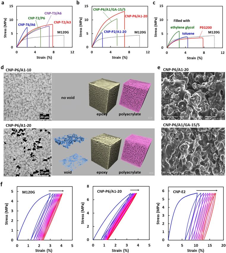
www.nature.com/scientificreports/
Figure 1. Process for the fabrication of epoxy monolith and CNP. (a) Chemical structure of compounds used
for the fabrication of epoxy monolith. (b) Chemical structure of compounds used as the second component of
the CNPs. c, Schematic illustration for the fabrication and characterization of epoxy monolith sheets and the
CNPs.
A monolith with a three-dimensional continuous network skeleton and through holes has been applied
as a high-performance material, of which a high porosity and strength are used for the separation, reaction,
and other f unctions29,30, e.g., HPLC c olumns31,32, supports for c atalysts33, separators for lithium-ion b
atteries34,
35–37
and dissimilar materials b onding . We now propose a new strategy for the synthesis of toughened polymer
materials using an epoxy monolith. In this study, we have successfully controlled the mechanical properties of
co-continuous network polymers (CNPs) synthesized by filling the continuous pores of an epoxy monolith with
different cured resins. We fabricated three kinds of CNPs containing epoxy resins, thiol‒ene thermosets, and
polyacrylates as the cross-linked second polymers in order to control the strength and toughness by a sacrificial
fracture mechanism. The structure, thermal, and mechanical properties of the monolith and the fabricated CNPs
were investigated.
Epoxy monolith
A mixture of an epoxy resin (E1), a diamine as the curing agent (BACM), and a porogen (PEG200) shown in
Fig. 1a was thermally cured on a glass or aluminum (Al) plate in order to fabricate the epoxy monolith (Fig. 1c).
After immersion in water to remove the porogen, a flexible and foldable monolith sheet, as shown in Fig. 2a,
was peeled from the plate. This unique flexible property is due to the presence of continuous pores in the sheet.
Non-destructive observations using a 3D X-ray imaging t echnique38,39 can visualize the porous structure of
the epoxy monolith. In this imaging method, any desired 3D and cross-sectional (2D) images are visualized by
computer tomography from X-ray projection images for various kinds of composites40–44. Figure 2b shows the 3D
structures of an exfoliated monolith sheet. The 3D X-ray imaging has revealed the fine structure of the internal
epoxy skeleton. In this study, several monolith sheets with different sizes of the porous structures were prepared
by changing the fabrication conditions, such as the curing temperature (120 or 130 °C) and the substrate (a glass
or Al plate). As shown in the cross-sectional images of the X-ray CT in Fig. 2c, the sizes of the epoxy frames
and pores were variable depending on the curing conditions of the epoxy. In Fig. 2d, the monolith skeletons
are emphasized by a beige color. The average thickness of the monolith skeleton can be assessed using the local
thickness determined by fitting maximum spheres to the structure45. Figure 2e illustrates the distribution of the
monolith thickness for the inner structure of the sheets. The size of the continuous epoxy skeleton significantly
depended on the conditions for the monolith fabrication; i.e., the epoxy monolith sheets consisting of fine pillars
with a 7.5 ± 1.8 µm thickness during the fabrication using the Al plate with a high thermal conductivity, while the
monolith with a larger thickness and broad distribution (10.3 ± 2.8 µm) was produced on the glass plate. As the
curing temperature increased, the pillar diameter decreased (Fig. 2c). It was previously reported that the mono-
lith structure also depended on the formulation of the epoxy resins (See Supplementary Table 1 in Supporting
Information)35. A fine monolith structure was formed by the fast cross-linking reaction at an earlier stage during
the Ostwald propagation of the phase-separated structure via a spinodal decomposition30. Figure 2f indicates
the epoxy occupancy as a function of the position along a direction vertical to the sheet plane. It revealed the
Scientific Reports | (2021) 11:1431 | https://doi.org/10.1038/s41598-021-80978-2 2
Vol:.(1234567890)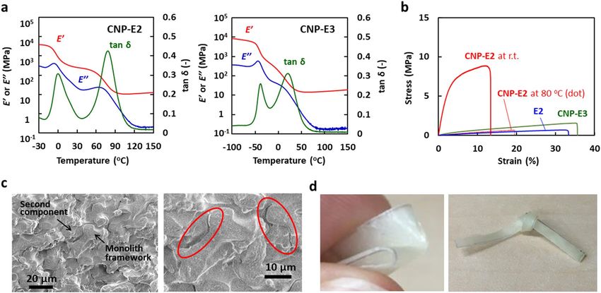
www.nature.com/scientificreports/
presence of skin layers with a thickness less than 10 μm in the areas near both surfaces. An epoxy-rich phase is
favorably distributed at the surface (closed to air) and the interface (closed to the substrate) with a higher free
energy during the monolith fabrication p rocess34.
The thermal and mechanical properties of the monolith sheets are summarized in Table 1. There is no doubt
that the glass transition temperature (Tg) and the storage modulus (E’) of the monolith sheets are significantly low
compared to those of the corresponding bulk thermoset made in the absence of the porogen (Fig. 2g,h). The Tg
and E’ values estimated by DMA were 102–107 °C and 319–521 MPa (at 25 °C) for the monolith sheets, respec-
tively. The Tg and E’ values of E1 as the bulk thermoset were 175 °C and 1950 MPa, respectively. The strength at
break of the monoliths was as low as 5.3–6.3 MPa for the tensile test, being independent of the coarse structure
of the monoliths. These strength values were one tenth of the value for the bulk thermoset (45.8 MPa). The dif-
ference in the mechanical properties of the monolith and bulk materials is related to the presence or absence of
a porous structure. On the other hand, the thermal property of the monolith (Fig. 2h) cannot be explained by
the porous structure. It is assumed that the PEG200 incorporated inside the epoxy cure remains and acts as a
plasticizer during the fabrication of the m onolith30.
Thus, the major factor why the monolith sheets exhibit mechanical properties different from the bulk cured
product is ascribed to the porous structure inside the monolith. Therefore, we have proposed a toughening of the
epoxy monolith by filling the pores with different flexible and stretchable cured materials, which are expected to
compensate for the disadvantages of the hard and brittle epoxy resins.
CNP filled with epoxy resins
The low-Tg epoxy resins (Fig. 1b) were initially used as the second component to fabricate the epoxy/epoxy CNPs,
in which two kinds of epoxy resins with different characteristics have independent continua. The CNPs were
semi-transparent materials, being in contrast to the opaque monolith sheet that strongly scatters visible light. The
SEM image of the CNP cross-section showed that the pores of the original monolith were filled with the second
epoxy resin without gaps. The DMA curves of the CNP-E2 and CNP-E3 (Fig. 3a) indicate a two-step glass transi-
tion for both composites, of which the peak on the lower temperature side is attributed to the Tg of the E2 or E3
network, and the higher temperature peak is of the hard network of E1. The Tg values of the hard component are
lower than those of the bulk thermoset and the monolith before filling the second soft epoxy (see also Table 1).
In addition, they depended on the Tg of the second components. It is due to the occurrence of the further reac-
tion of an added low-Tg epoxy with the monolith component at the second curing step. The interpenetration
of the second epoxy changes the mechanical property of the monolith structure as the first component. The E’
value of CNP-E2 and CNP-E3 were 266 MPa and 34 MPa at 25 °C, respectively, which are lower than 521 MPa
for the original monolith. Thus, it has been clarified that the second epoxy resin penetrates into the hard epoxy
skeleton during the fabrication process of the CNPs, and leads to lowering the Tg of the hard epoxy component.
Both the elastic and plastic deformation processes were confirmed in the stress–strain curve of CNP-E2
with the Tg values above and below room temperature (Fig. 3b). The strength at break reached 8.3 MPa, which
was greater than the value for the monolith sheets. The shape of the curve for CNP-E2 was similar to that of the
epoxy monolith without filling the second epoxy except for the breaking strength (Fig. 2g). In contrast, another
composite, CNP-E3, showed a soft appearance and formed a stress–strain curve peculiar to ductile materials at
room temperature. When the tensile test of CNP-E2 was conducted at a temperature higher than the Tg, the curve
showed elastic deformation with a small slope. This temperature-dependent mechanical property was revers-
ible. In the SEM images of a test piece of CNP-E2 after the tensile measurement (Fig. 3c), the fracture surface
was not smooth and contained many small undulations. In the expanded images, some gaps between the two
components were detected but the continuous structure of each component remained. The two components were
distinguishable because one of them included many small pores in the epoxy skeleton30. Consequently, CNP-E2
has an excellent fracture toughness. In fact, it can be folded and knotted (Fig. 3d). Interestingly, the strain at
break as well as the toughness increased with an increase in the structural coarseness of the used monolith (see
Supplementary Table 1 in Supporting Information), although the strength at break simultaneously decreased.
Thus, it has been revealed that the mechanical strength and flexibility of the CNPs depend on the microstructure
of the co-continuous components.
In comparison with the mechanical properties of the bulk thermoset, it is clear that the monolith sheets
exhibit a large deformation at a weaker applied force, as already shown in Fig. 2g. The deformation process of
the porous materials, such as the monolith, includes the macroscopic morphological change of a mesh structure,
being represented by the KIRIGAMI model46–48. For the deformation of the monolith, the epoxy skeleton with
a high elasticity undergoes a slight bending and twisting, but they can result in a large deformation of the entire
monolith with a small external stress. In an initial region for the stress‒strain relationship of the monoliths
(for example, less than 1% strain for M120G), the deformation process was almost reversible, with very little
hysteresis. Further stretching caused irreversible and partial breakage of the epoxy skeleton, which creased a
large hysteresis (See also the results for repeated tensile tests in Fig. 4f and Supplementary Fig. 8). For the CNPs,
the fracture of the hard epoxy component occurs during the large deformation, but the destruction of the entire
material is suppressed due to the flexible second epoxy networks.
CNP filled with acrylic thermosets
CNP was next prepared by thiol‒ene thermosets using polyfunctional thiols and acrylates as the secondary fill-
ing component (Fig. 1b). Similar to the CNP filled with the low-Tg epoxy, the SEM images of the cross section
confirmed that the monolith pores were successfully filled with the second component without any gaps. Based
on the DMA curves, the two peaks due to the expected two kinds of transitions were confirmed (Table 2). The
Tg observed in the high temperature region was high and independent of the Tg of the second components. It
Scientific Reports | (2021) 11:1431 | https://doi.org/10.1038/s41598-021-80978-2 3
Vol.:(0123456789)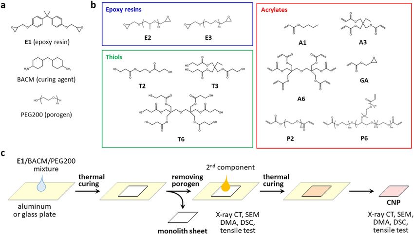
www.nature.com/scientificreports/

          Scientific Reports |   (2021) 11:1431 |   https://doi.org/10.1038/s41598-021-80978-2   4

Vol:.(1234567890)
www.nature.com/scientificreports/
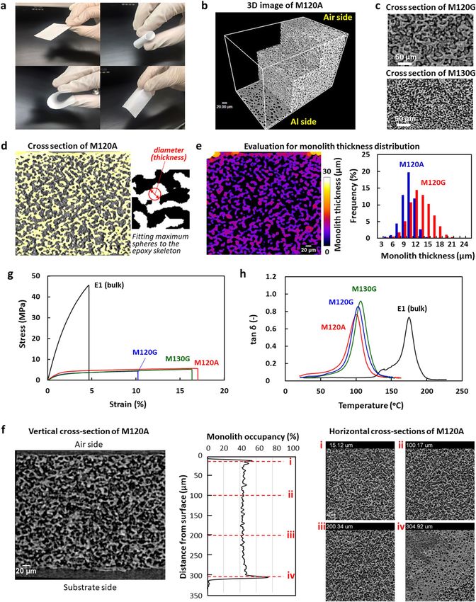
◂Figure 2. Porous structure (a–f) and mechanical and thermal properties (g,h) of the monolith sheets. (a)
Appearance of epoxy monolith sheets. The thickness was 326 µm and 168 µm for the left and right images,
respectively. The thin monolith sheet was foldable like paper. (b) 3D X-ray CT image of monolith sheet
(M120A). (c) Cross-sectional images of monolith sheets with different monolith thicknesses (M120G and
M130G). (d) Evaluation of local thickness of the epoxy skeleton for M120A, determined by fitting maximum
spheres to the structure, according to the method described in the literature (ref. 45). The contribution due to
the epoxy particles present in the pores was excluded during the estimation of the epoxy pillar thickness and
the pore size. (e) Distribution of the monolith thickness for M120A (left figure). The blue and red curves in the
right figure are the distribution for M120A with a fine structure and M120G with a coarse structure. (f) Vertical
(left) and horizontal (right) cross-section images of M120A and the monolith occupancy as the function of the
distance from the air-side surface (center). (g,h) Stress–strain curves of the tensile test and tanδ peaks from the
DMA measurements for the monolith sheets with different coarseness (M120G, M120A, and M130G) and the
bulk thermoset of E1.
supports the fact that the thiol‒ene reaction at the second stage orthogonally proceeds49 without affecting the
physical properties of the first epoxy component. In Fig. 4a and Table 2, the results of a tensile test are sum-
marized for the CNPs prepared using the various thiol‒ene thermosets. The strength at break for CNP-T6/A6
was improved to 1.7 times that of the original monolith, but the strain was reduced to 1/3. In the system with
hexafunctional thiols and acrylates, the cross-linking density of the second network is too high, leading to the
formation of a brittle composite. When the number of functional groups of each compound was reduced to 2
or 3 (T2, T3, or A3), the strength increased to 6.4‒7.3 MPa while maintaining the elongation property of the
original monolith. In Table 2, the Tg values are also summarized for the CNPs as well as the values for the second
networks. They support the enlarged toughness for the CNPs containing the second components in the rubber
state. It was also clarified that a composite exhibiting high strength and strain values was available when P6,
which is a star-shaped PEG with six terminal acrylate moieties (see Fig. 1b), was used in combination with T2.
Therefore, the scope of the materials design was expanded to the radical polymerization system of acrylates.
When radical polymerization of an acrylic monomer is used for filling the pores, the problem of volume
shrinkage associated with the polymerization is inevitable because it is an inherent feature of the vinyl polym-
erization. In fact, attempting to produce the CNPs using conventional acrylic monomers such as A1 and A6,
caused a large warpage and undulation of the composites. This is unlike the negligible shrinkage that was seen in
the epoxy and thiol‒ene curing systems, as already described. In contrast to the volume-shrinking conventional
monomers, the single use of P6 provided a flexible CNP of which the strength and stain values at break were as
high as 8.0 MPa and 9.8%, respectively. The modulus was somewhat low at 227 MPa. The cross-sectional SEM
image of CNP-P6 revealed that there were no gaps at the interface between the co-continuous dual components.
In the copolymerization system of P6 and A1, the gaps increased as the composition of A1 increased and many
voids were detected for the samples including 20% of A1 (Fig. 4d,e). The X-ray CT imaging has confirmed that the
voids are unevenly distributed in the CNPs. As the results of the mechanical tests, the CNP-P6/A1-20 exhibited
the highest strength and toughness (Table 2). On the other hand, the toughness was significantly reduced for
CNP-P2/A1-20 with a low cross-linking density for the second network, which was prepared using a telechelic
polyacrylate P2 in place of the multifunctional P6.
In order to discuss the effect of the gaps between the two co-continuous structures on the mechanical prop-
erties, we prepared the CNPs in the presence of GA (See Fig. 1b for the chemical structure) during the thermal
curing process at the second step. The glycidyl group of GA is expected to react with the functional groups in the
epoxy monolith skeleton and to suppress the formation of gaps in the CNP. As the results of the X-ray CT imaging
and the tensile test, it has been clarified that these is no gap in the produced CNPs and the strength and strain
values at break are lower, as shown in Table 2 and Fig. 4b (See also X-ray CT images in Supplementary Fig. 7).
They indicated the important role of the sliding of mutual components on resistance to mechanical fracture dur-
ing the large deformation of the CNPs, leading to effective energy dissipation to prevent macroscopic material
destruction. In this study, a repeated tensile test was also conducted. During the repeated measurements under
the maximum applied forces of 20‒40 N, the cyclic curves shifted with a hysteresis as shown in Fig. 4f and the
degree of the shift for the CNP (CNP-P6/A1-20) was smaller than that of the original monolith (M120G). This
indicates the suppression of the fatigue of the rigid epoxy continuum surrounded by the flexible elastomer as
the second component. The epoxy/epoxy CNPs gave similar trajectory, but the pushback effect of the second
component has become weaker. Furthermore, it was revealed that the CNPs containing a viscous liquid as the
second component resulted in no improvement in the strength (Fig. 4c). Similar results were obtained for the
sample without removing the porogen after the curing of the first epoxy material during the fabrication process
of the monolith sheets. Thus, the liquid materials act like a plasticizer for the CNP, but no toughening effect.
Outlook
In this study, we have successfully fabricated the CNPs as new composite materials and evaluated their strength
and toughness. The epoxy monolith is a unique material, which has co-continuous structure of an epoxy skeleton
and pores leading to its flexible and foldable properties despite the epoxy cured materials with a high Tg. The
CNPs were prepared by filling the voids in the monolith with any second cross-linked polymers. Based on the
results of three systems using epoxy, thiol‒ene thermosets, and polyacrylates as the second filler components,
we determined the requirements for strengthening the CNP as follows. The epoxy monolith is in a glassy state
and the second one should be a moderately cross-linked polymer in the rubbery state. In the case of DN gels
as the most typical example of artificial toughened polymers by the sacrificial fracture approach, the structural
Scientific Reports | (2021) 11:1431 | https://doi.org/10.1038/s41598-021-80978-2 5
Vol.:(0123456789)www.nature.com/scientificreports/
E’ at Strength Strain
Tg a 25 oCa at breakb at breakb Modulusb
Material Sample code (oC) (MPa) (MPa) (%) (MPa)
M120G 103 319 5.03 ± 0.63 10.7 ± 0.5 318 ± 37
Monolith sheetc M120A 102 521 6.26 ± 0.57 16.2 ± 2.1 394 ± 24
M130G 107(100) 450 5.55 ± 0.21 17.2 ± 1.2 290 ± 14
8.31 ± 0.67 11.4 ± 1.5 253 ± 35
CNP-E2 ‒ 0.3, 78.5 266
Co-continuous network polymerd (0.67 ± 0.14)e (17.4 ± 6.8)e (4.9 ± 0.7)e
CNP-E3 ‒ 38.2, 20.4 34 1.84 ± 0.58 41.5 ± 14.3 11.9 ± 0.8
E1 175 1950 45.8 ± 6.1 4.6 ± 1.1 1640 ± 71
Bulk thermosetr
E2 ‒ ‒ 0.70 ± 0.02 31.5 ± 0.9 3.5 ± 0.2
Table 1. Thermal and mechanical properties of the monolith sheets, the CNPs with E2 and E3, and the bulk
thermosets of E1 and E2. a Based on tanδ peak temperature of DMA measured at the frequency of 1 Hz and
the heating rate of 2 °C/min. Values in parentheses indicate Tg values determined by DSC from the second
heating process at the heating rate of 10 °C/min. b Based on the tensile test at the rate of 1 mm/min and room
temperature. Modulus was determined in the strain range of 0.05–0.25% c M120G and M120A were prepared
on glass and Al plates, respectively, at 120 °C. M130G was prepared on a glass plate at 130 °C. d CNP-E2 and
CNP-E3 were prepared using M120A as the monolith sheet. e Values in parentheses indicate those determined
at 80 °C. f Bulk thermoset prepared by thermal curing of an epoxy resin (E1 or E2) with BACM in the absence
of PEG200 as the porogen.
Figure 3. Thermal and mechanical properties of the CNPs filled with soft epoxy resin. (a) Temperature
dependence of E’ and tanδ for CNP-E2 and CNP-E3 determined by DMA at a frequency of 1 Hz and the heating
rate of 2 °C/min. (b) Stress–strain curves of CNP-E2 measured at room temperature and 80 °C, CNP-E3 at
room temperature, and the bulk thermoset of E2 at room temperature. (c) SEM image of the fracture surface of
CNP-E2 after the tensile test. Some gaps are detected at the interface of the two components. The right image
is expanded and red ellipsoids indicate the formation of large gaps between the first and second components.
In these SEM images, each co-continuous domain of the two different epoxies is distinctly observed. Smaller
pores with a size less than a micrometer are seen in the monolith skeleton, being formed by a secondary phase
separation during the first fabrication process of the epoxy monolith (see also ref. 30). (d) Photographs of
the folded and tied CNP-E2. For the fabrication of the CNPs filled with epoxy resins, M120A was used as the
monolith sheet.
features of the DN gels are summarized as f ollows24: The first network has a rigid structure and the second
network has a flexible structure. The concentration of the second network is much higher than that of the first
network, and the first network is densely cross-linked. When the second network is loosely or not cross-linked,
the gels become stronger. The sacrificial fracture mechanism has been applied to soft materials, such as DN gel
and elastomers. In this study, we have demonstrated that the sacrificial fracture mechanism is adjustable for
toughening the CNPs as the hard composites as well as the unique mechanical property of the epoxy monolith
Scientific Reports | (2021) 11:1431 | https://doi.org/10.1038/s41598-021-80978-2 6
Vol:.(1234567890)www.nature.com/scientificreports/
Figure 4. Mechanical properties and X-ray CT and SEM images of the CNPs filled with thiol–ene thermosets
and polyacrylates. (a) Stress–strain curves of the CNPs filled with thiol–ene thermosets. See Fig. 1b for the
chemical structure of the polyfunctional thiols and acrylates. (b) Stress–strain curves of the CNPs filled with
polyacrylates. (c) Stress–strain curves of the monolith sheet (M120G) filled with PEG200, ethylene glycol, and
toluene as the liquid materials for the second component. (d) X-ray CT images of CNP-P6/A1-10 and CNP-P6/
A1-20. Cross-section images are reconstructed in the horizontal direction for the area near the bottom surface
of the CNPs. The X-ray CT images were analyzed by the phase contrast imaging (PCI) method (ref.50) and they
are represented for each component, i.e., the polyacrylate, the epoxy, and the void corresponding to the light
gray, dark grey, and black areas in the left cross-section images. (e) SEM images of the fracture surfaces of CNP-
P6/A1-20 and CNP-P6/A1/GA-15/5 after the tensile test. (f) Hysteresis stress–strain curves of the monolith
sheet (M120G, left), CNP-P6/A1-20 (center), and CNP-E2 (right). The maximum applied forces were 20, 30,
and 40 N, respectively.
Scientific Reports | (2021) 11:1431 | https://doi.org/10.1038/s41598-021-80978-2 7
Vol.:(0123456789)www.nature.com/scientificreports/
Tg a Strain at breakb Modulusb Toughnessc
Sample code (oC) Strength at breakb (MPa) (%) (MPa) (kJ/m2)
CNP-T6/A6d 48 [57], 140 7.29 2.28 396 0.94
CNP-T3/A6e 9.8 [21], 150 6.40 ± 1.01 6.07 ± 1.01 207 ± 9.7 2.6 ± 0.84
CNP-T2/A3 [‒ 12] 7.15 ± 1.12 6.08 ± 1.71 210 ± 51 3.0 ± 1.5
CNP-T2/P6 ‒ 42 [‒42] 7.25 ± 0.056 5.30 ± 0.13 219 ± 15 2.3 ± 0.04
CNP-P6f.,g ‒ 44, 117 8.00 ± 1.50 9.76 ± 1.94 227 ± 22 5.5 ± 2.0
CNP-P6/A1-10 ‒ 9.47 ± 0.97 4.18 ± 1.23 356 ± 50 2.5 ± 1.0
CNP-P6/A1-20 h ‒ 50 [‒ 42], 121 12.4 ± 0.67 7.12 ± 0.11 437 ± 26 6.1 ± 0.20
CNP-P6/A1-30 ‒ 11.3 ± 0.36 5.67 ± 0.61 444 ± 3.2 4.3 ± 0.67
CNP-P6/A1/GA-18/2 ‒ 7.50 ± 0.71 3.91 ± 1.20 329 ± 65 1.9 ± 0.76
CNP-P2/A1-20 [‒ 28] 4.36 ± 0.54 1.44 ± 0.00 388 ± 26 0.34 ± 0.04
Table 2. Thermal and mechanical properties of the CNPs using M120G as the monolith sheet and acrylic
thermosets as the second component. a Based on the tanδ peak temperature of DMA measured at a frequency
of 1 Hz and a heating rate of 2 °C/min. Values in bracket indicate Tg values for the bulk thermosets of the
second component determined by DMA. b Based on the tensile test at the rate of 1 mm/min and room
temperature. The modulus was determined in the strain range of 0.05–0.25% c Evaluated based on an area
below each stress–strain curve. The toughness values of M120G was 4.4 ± 0.77 kJ/m2. d The E’ values of CNP-
T6/A6 were 1680, 309, and 8.9 MPa at 25, 100, and 180 °C, respectively, determined by DMA. e The E’ values
of CNP-T3/A6 were 240 and 17.5 MPa at 80 and 180 °C, respectively, determined by DMA. f M120A was used
instead of M120G. g The E’ values of CNP-P6 were 3170, 324, and 23.1 MPa at ‒80, 0, and 160 °C, respectively,
determined by DMA. h The E’ values of CNP-P6/A1-20 were 5530, 839, and 29.6 MPa at ‒80, 0, and 160 °C,
respectively, determined by DMA.
itself. Some features for the fracture of the toughened epoxy composites may be different from those of the soft
materials. The monolith structure can be fabricated using various materials other than epoxy resin. Therefore, the
variation in the combination of the dual network polymer materials of the high-strength CNPs will be expanded
in the future, leading to their use in a wide range of application fields.
Received: 12 November 2020; Accepted: 1 January 2021
References
1. Domun, N. et al. Improving the fracture toughness and the strength of epoxy using nanomaterials: a review of the current status.
Nanoscale 7, 10294–10329 (2015).
2. Quaresimin, M., Schulte, K., Zappalorto, M. & Chandrasekaran, S. Toughening mechanism in polymer nanocomposites: from
experiments to modelling. Comput. Sci. Technol. 123, 187–204 (2016).
3. Creton, C. Networks and gels: soft but dynamic and tough. Macromolecules 50, 8297–8316 (2017).
4. Mashouf Roudsari, G., Mohanty, A. K. & Misra, M. Green approaches to engineer tough biobased epoxies: a review. ACS Sustain.
Chem. Eng. 5, 9528–9541 (2017).
5. Clancy, A. J., Anthony, D. B. & de Luca, F. Metal mimics: lightweight, strong, and tough nanocomposites and nanomaterials
assemblies. ACS Appl. Mater. Interfaces 12, 15955–15975 (2020).
6. Haque, Md. A., Kurokawa, T. & Gong, J. P. Super tough double network hydrogels and their application as biomaterials. Polymer
53, 1805–1822 (2012).
7. Okumura, Y. & Ito, K. The polyrotaxane gel: a topological gel by figure-of-eight cross-links. Adv. Mater. 13, 485–487 (2001).
8. Sakai, T. et al. Design and fabrication of a high-strength hydrogel with ideally homogeneous network structure from tetrahedron-
like macromonomers. Macromolecules 41, 5379–5384 (2008).
9. Usuki, A. et al. Snthesis of nylon 6-clay hybrid. J. Mater. Res. 8, 1179–1184 (1993).
10. Haraguchi, K. & Takehisa, T. Nanocomposite hydrogels: a unique organic-inorganic network structure with extraordinary mechani-
cal, optical, and swelling/deswelling properties. Adv. Mater. 14, 1120–1124 (2002).
11. Sano, K., Ishida, Y. & Aida, T. Synthesis of anisotropic hydrogels and their applications. Angew. Chem. Int. Ed. 57, 2532–2543
(2018).
12. Zou, W., Dong, J., Luo, Y., Zhao, Q. & Xie, T. Dynamic covalent polymer networks: from old chemistry to modern day innovations.
Adv. Mater. 29, 1606100 (2017).
13. Denissen, W. et al. Chemical control of the viscoelastic properties of vinylogous urethane vitrimers. Nat. Commun. 8, 14857 (2017).
14. Kinloch, A. J., Shaw, S. J., Tod, D. A. & Hunston, D. L. Deformation and fracture behavior of a rubber-toughened epoxy. 1. Micro-
structure and fracture studies. Polymer 24, 1341–1354 (1983).
15. Pearson, R. A. & Yee, A. F. Toughening mechanisms in elastomer-modified epoxies. Part 2. Microscopy studies. J. Mater. Sci. 21,
2475–2488 (1986).
16. Pearson, R. A. & Yee, A. F. Toughening mechanisms in thermoplastic-modified epoxies. 1. Modification using poly(phenylene
oxide). Polymer 34, 3658–3670 (1993).
17. Kinloch, A. J. & Young, R. J. Fracture Behaviour of Polymers 421–471 (Elsevier Science, Amsterdam, 1983).
18. Hodgkin, J. H., Simon, G. P. & Varley, R. J. Thermoplastic toughening of epoxy resins: a critical review. Polym. Adv. Technol. 9,
3–10 (1998).
19. Kinloch, A. J. & Taylor, A. C. The mechanical properties and fracture behaviour of epoxy-inorganic micro- and nano-composites.
J. Mater. Sci. 41, 3271–3297 (2006).
20. Carolan, D., Ivankovic, A., Kinloch, A. J., Sprenger, S. & Taylor, A. C. Toughening of epoxy-based hybrid nanocomposites. Polymer
97, 179–190 (2016).
Scientific Reports | (2021) 11:1431 | https://doi.org/10.1038/s41598-021-80978-2 8
Vol:.(1234567890)www.nature.com/scientificreports/
21. Kumar, S., Krishnan, S., Samal, S. K., Mohanty, S. & Nayak, S. K. Toughening of petroleum based (DGEBA) epoxy resins with
various renewable resources based flexible chains for high performance applications: a review. Ind. Eng. Chem. Res. 57, 2711–2726
(2018).
22. Yang, Q., Adrus, N., Tomicki, F. & Ulbricht, M. Composites of functional polymeric hydrogels and porous membranes. J. Mater.
Chem. 21, 2783–2811 (2011).
23. Annabi, N. et al. Rational design and applications of hydrogels in regenerative medicine. Adv. Mater. 26, 85–124 (2014).
24. Gong, J. P. Why are double network hydrogels so tough?. Soft Matt. 6, 2583–2590 (2010).
25. Zhou, X., Guo, B., Zhang, L. & Hu, G.-H. Progress in bio-inspired sacrificial bonds in artificial polymeric materials. Chem. Soc.
Rev. 46, 6301–6329 (2017).
26. Fan, H. & Gong, J. P. Fabrication of bioinspired hydrogels: challenges and opportunities. Macromolecules 53, 2769–2782 (2020).
27. King, D. R., Okumura, T., Takahashi, R., Kurokawa, T. & Gong, J. P. Macroscale double networks: design criteria for optimizing
strength and toughness. ACS Appl. Mater. Interfaces 11, 35343–35353 (2019).
28. Ducrot, E., Chen, Y., Bulters, M., Sijbesma, R. P. & Creton, C. Toughening elastomers with sacrificial bonds and watching them
break. Science 344, 186–189 (2014).
29. Nakanishi, K. & Tanaka, N. Sol-gel with phase separation. Hierarchically porous materials optimized for high-performance liquid
chromatography separations. Acc. Chem. Res. 40, 863–873 (2007).
30. Tsujioka, N., Ishizuka, N., Tanaka, N., Kubo, T. & Hosoya, K. Well-controlled 3D skeletal epoxy-based monoliths obtained by
polymerization induced phase separation. J. Polym. Sci. A Polym. Chem. 46, 3272–3281 (2008).
31. Svec, F. Porous polymer monoliths: amazingly wide variety of techniques enabling their preparation. J. Chromato. A 1217, 902–924
(2010).
32. Guillarme, D., Ruta, J., Rudaz, S. & Veuthey, J.-L. New trends in fast and high-resolution liquid chromatography: a critical com-
parison of existing approaches. Anal. Bioanal. Chem. 397, 1069–1082 (2010).
33. Nijhuis, T. A. et al. Preparation of monolithic catalysts. Catal. Rev. 43, 345–380 (2001).
34. Sakakibara, K., Kagata, H., Ishizuka, N., Sato, T. & Tsujii, Y. Fabrication of surface skinless membranes of epoxy resin-based
mesoporous monoliths toward advanced separators for lithium ion batteries. J. Mater. Chem. A 5, 6866–6873 (2017).
35. Uehara, F. & Matsumoto, A. Metal-resin bonding mediated by epoxy monolith layer. Appl. Adhes. Sci. 4, 18 (2016).
36. Sugimoto, Y., Nishimura, Y., Uehara, F. & Matsumoto, A. Dissimilar materials bonding using epoxy monolith. ACS Omega 3,
7532–7541 (2018).
37. Sakata, N., Takeda, Y., Kotera, S., Suzuki, Y. & Matsumoto, A. Interfacial structure control and three-dimensional x-ray imaging
of an epoxy monolith bonding system with surface modification. Langmuir 36, 10923–10932 (2020).
38. Maire, E. & Withers, P. J. Quantitative X-ray tomography. Int. Mater. Rev. 59, 1–43 (2014).
39. Garcea, S. C., Wang, Y. & Withers, P. J. X-ray computed tomography of polymer composites. Comput. Sci. Technol. 156, 305–319
(2018).
40. Schilling, P. J., Karedla, B.-P.R., Tatiparthi, A. K., Verges, M. A. & Herrington, P. D. X-ray computed microtomography of internal
damage in fiber reinforced polymer matrix composites. Comp. Sci. Technol. 65, 2071–2078 (2005).
41. Lomov, S. V. et al. Experimental methodology of study of damage initiation and development in textile composites in uniaxial
tensile test. Comput. Sci. Technol. 68, 2340–2349 (2008).
42. Epting, W. K., Gelb, J. & Litster, S. Resolving the three-dimensional microstructure of polymer electrolyte fuel cell electrodes using
nanometer scale X-ray computed tomography. Adv. Funct. Mater. 22, 555–560 (2012).
43. Yu, B., Bradley, R. S., Soutis, C., Hogg, P. J. & Withers, P. J. 2D and 3D imaging of fatigue failure mechanisms of 3D woven com-
posites. Comp. A 77, 37–49 (2015).
44. Chowdhury, N. T. et al. Design of an uncontaminated textile CFRP specimen optimised for both mechanical testing and X-ray
microtomography. Comp. A 123, 208–221 (2019).
45. Hildebrand, T. & Rüegsegger, P. A new method for the model-independent assessment of thickness in three-dimensional images.
J. Microsc. 185, 67–75 (1997).
46. Xu, L., Shyu, T. C. & Kotov, N. A. Origami and Kirigami nanocomposite. ACS Nano 11, 7587–7599 (2017).
47. Shyu, T. C. et al. A kirigami approach to engineering elasticity in nanocomposites through patterned defects. Nature Mater. 14,
785–789 (2015).
48. Sakumichi, N. & Okumura, K. Exactly solvable model for a velocity jump observed in crack propagation in viscoelastic solids. Sci.
Rep. 7, 8065 (2017).
49. Corrigan, N., Ciftci, M., Jung, K. & Boyer, C. Mediating reaction orthogonality in polymer and materials science. Angew. Chem.
Int. Ed. https://doi.org/10.1002/anie.201912001 (2019).
50. Kalasová, D. et al. Characterization of a laboratory-based X-ray computed nanotomography system for propagation-based method
of phase contrast imaging. IEEE Trans. Instrum. Meas. 69, 1170–1178 (2020).
Acknowledgements
We thank Mr. Juhei Kuriyama and Ms. Yukiko Miyaji of Sakamoto Yakuhin Kogyo Co. Ltd., Osaka, Japan, for
providing SA-TE60 (P6) and some other chemicals.
Author contributions
A.M. planned the study. R.T. and Y.N. performed the synthetic experiments and characterization. Y.T. performed
the X-ray CT experiments. Y.S. and M.K. analyzed the results. A.M. wrote the paper. All authors were involved
in the discussion of the results and commented on the manuscript.
Competing interests
The authors declare no competing interests.
Additional information
Supplementary Information The online version contains supplementary material available at https://doi.
org/10.1038/s41598-021-80978-2.
Correspondence and requests for materials should be addressed to A.M.
Reprints and permissions information is available at www.nature.com/reprints.
Publisher’s note Springer Nature remains neutral with regard to jurisdictional claims in published maps and
institutional affiliations.
Scientific Reports | (2021) 11:1431 | https://doi.org/10.1038/s41598-021-80978-2 9
Vol.:(0123456789)www.nature.com/scientificreports/
Open Access This article is licensed under a Creative Commons Attribution 4.0 International
License, which permits use, sharing, adaptation, distribution and reproduction in any medium or
format, as long as you give appropriate credit to the original author(s) and the source, provide a link to the
Creative Commons licence, and indicate if changes were made. The images or other third party material in this
article are included in the article’s Creative Commons licence, unless indicated otherwise in a credit line to the
material. If material is not included in the article’s Creative Commons licence and your intended use is not
permitted by statutory regulation or exceeds the permitted use, you will need to obtain permission directly from
the copyright holder. To view a copy of this licence, visit http://creativecommons.org/licenses/by/4.0/.
© The Author(s) 2021
Scientific Reports | (2021) 11:1431 | https://doi.org/10.1038/s41598-021-80978-2 10
Vol:.(1234567890)You can also read