From Prototyping to Serial Production - 3D-Printing in Ceramic Manufacturing
←
→
Page content transcription
If your browser does not render page correctly, please read the page content below
PROCESS ENGINEERING
From Prototyping to Serial Production –
3D-Printing in Ceramic Manufacturing
F. Raether, J. Vogt
For two decades, Additive Manufacturing (AM) was used mainly for the rapid prototyping of visual or
functional models. However, with growing awareness of its potential and increasing performance of
3D-printers, it becomes more and more relevant for small- and medium-scale production. Quality Man
agement (QM) was no major issue in the period of prototyping but – besides production cost, process
integration and automation – it becomes a key enabling factor for the implementation of AM methods
in industrial production. It turns out that several challenges are to be met especially by ceramic AM to
comply with customary manufacturing methods.
1 Introduction in the small scale production of ceramic thermal stress and damage in ceramic parts.
There are five main reasons for the strong parts. For that reason, powder bed fusion and dir
growth of AM in component production: The growing variety of AM methods has ected energy deposition have only minor
• It enables extremely lightweight construc been classified in seven main categories: importance in the AM-based production of
tions, saving energy in transportation and Powder bed fusion, directed energy depos ceramics. The remaining five categories still
heating technology (Fig. 1 a). ition, material jetting, material extrusion, include a multitude of methods and vari
• It can substitute complex constructions sheet lamination, binder jetting and vat ations, reflecting the ingenuity of engineers
customarily fabricated from many individ photopolymerisation (ISO 17296-1). The all over the world. However, this diversity
ual components by integration in a single first two of these categories comprise can drive quality managers to despair.
piece, saving assembly costs (Fig. 1 b). single stage processes, where forming and
• It can be used for the manufacturing of densification is done simultaneously. The 2 Quality management with
individual components and is of particu other five categories require two stages in AM of ceramics
lar interest for the replacement of bones, ceramic 3D-printing. In the first stage, green When ceramic parts are fabricated by AM,
teeth or organ parts in medical engineer parts are formed, and in a second stage, the several challenges are to be met to achieve
ing. green parts are processed in a subsequent high strength and reliability as well as net
• It allows for the production on demand, heat treatment to obtain the final products. shape performance. As usual, strength and
enabling new routes in logistics and spare Recent reviews on AM of ceramics can be reliability are controlled by microstructure
parts supply. found in [1, 2]. homogeneity and surface roughness. Both
• It eliminates the manufacture of expen In one stage AM processes, high tempera are harder to achieve with AM than with
sive moulds, which is extremely important ture gradients are applied, creating high standard production. Deformation during
Friedrich Raether, Joachim Vogt
Fraunhofer Center for High Temperature
Materials and Design (HTL)
95448 Bayreuth
Germany
Corresponding author: F. Raether
E-mail: friedrich.raether@isc.fraunhofer.de
Keywords: additive manufacturing,
3D-printing, industrial production, Fig. 1 a–b Ceramic parts produced by 3D-printing: a) lightweight container for heat
quality management treatment of ceramic fibres; b) high temperature sensor for simultaneous measurement
of gas flow and temperature
cfi/Ber. DKG 97 (2020) No. 3-4 E 45
PROCESS ENGINEERING
plementation of AM in production started
with polymers, followed by metals and is
in an early stage in the case of ceramics.
This chronology is reflected by the number
of AM standards available for AM with dif
ferent materials.
So far, no specific standard for ceramic 3D-
printing exists. However, a number of gener
al standards can be used, e.g.: ISO 52910-
17 for DFAM, ISO 52915-16 for file formats,
ISO 52921-13 for coordinate systems and
test methodologies. Furthermore, a new
VDI guideline on the DFAM of ceramics (VDI
3405 Sheet 3.6) is currently in preparation
[4].
In the following sections, we address some
general aspects of quality control in 3D-
Fig. 2 Survey on quality issues related to 3D-printing of ceramics
printing of ceramics which are relevant
beyond individual AM methods. First of all,
sintering impairs net shape performance. In overhanging parts requiring support struc the control of green compact quality is out
addition, with direct printing techniques, i.e. tures during printing and sintering. Design lined, followed by the heat treatment and
material jetting and material extrusion, net for Additive Manufacture (DFAM) becomes final component inspection.
shape performance often is deteriorated by a separate discipline among the traditional
deviations during the printing process itself. Design for Manufacturing and Assembly 3 Control of green compact
An in-line dimensional control of printed (DFMA). quality
parts, which is used in a closed loop, is Specific software is available to support Since nearly all ceramic AM techniques
rarely used but would be strongly recom construction engineers [3]. However, spe are two-stage processes, first of all green
mended. Since the feedstock has to ful cialists in the field of DFAM are rare, and compacts are formed, which are available
fil additional requirements compared to the majority of engineers need professional for quality inspection. Yet, AM forming pro
standard production, feedstock inspection development to utilise the full potential of cesses are more complex than customary
is a critical issue in quality management AM. Other specific issues affect the process forming processes.
of AM processes (Fig. 2). Happily, numer ing, plant monitoring and final inspection Considering this, it is very helpful to opti
ous well suited methods, e.g. rheological (compare Fig. 2). mise 3D-printing parameters and feedstock
measurements, are available for feedstock Depending on its field of application, AM properties on the basis of key figures de
control. has to fulfil the same standards as custom rived from the green compacts. In doing so,
AM in particular offers completely new de arily production processes, e.g. EN/AS 9100 the subsequent heat treatment can be de
sign possibilities, e.g. freeform surfaces, grid in aerospace, IATF 16949 in the automotive veloped separately (compare next section)
structures, undercuts and cavities. On the industry and ISO 13485 in medical technol – reducing the complexity of the entire pro
other hand, special restrictions exist, e.g. ogy. Due to its technical complexity, the im cess development considerably. The criteria
for green compact quality are the same as
for customary forming: close match to set
shape, homogenous and dense packing of
ceramic particles, homogenous distribution
of the binder, smooth surfaces and absence
of flaws like voids or delaminations.
Therefore, in principle the same methods can
be used for characterisation of AM green
compacts as those with standard processes
[5]. However, due to the complex geometry
of AM green parts, measuring shape usually
is more complicated than with green parts
from standard forming processes.
Fig. 3 a–b Measurement of homogeneity and layer structure of 3D-printed alumina This suggests using Computed Tomography
green compacts: a) cross section of a part produced by binder jetting measured by com- (CT) as a non-contact method, which can
puted tomography; b) cross section of a part produced by vat photopolymerisation and measure any shape, e.g. very fine struts
measured by scanning electron microscopy after cross section polishing or cavities. In addition, micro- or nano-CT
E 46 cfi/Ber. DKG 97 (2020) No. 3-4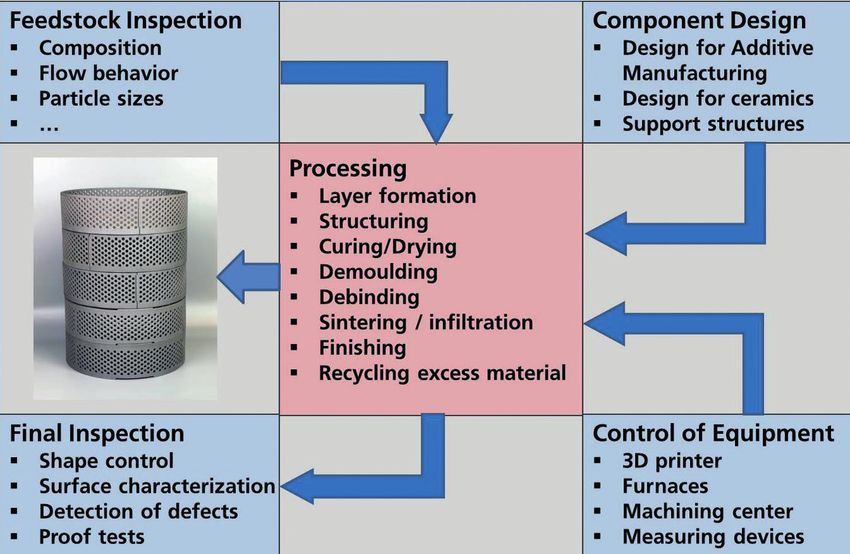
PROCESS ENGINEERING
Fig. 4 Heat and mass flow during debinding Fig. 5 Work flow during systematic optimisation of debinding
cycles
detects flaws and rough structures at the to resolve details of microstructure. By Yet, these structures are one of the most
parts’ surfaces. means of cross section polishing, a clean powerful characteristics of AM components.
Moreover, CT can be used to analyse special cut through the green compact can be ob In order to overcome difficulties with heat
structural features occurring with AM. There tained. Scanning Electron Microscopy (SEM) treatment, a systematic approach is re
are three two-stage AM techniques using is used to investigate the structure with quired which is outlined in the following
a layerwise building of the 3D-structure: high resolution (Fig. 3 b). It can be observed paragraphs separately for debinding and
sheet lamination, binder jetting and vat that the particle density between the layers sintering.
photo polymerisation. Structuring is done is lower. The overall homogeneity is much The thermal decomposition and combustion
within the layers, after the entire compon higher than in case of binder jetting, being of binder and other organic constituents
ent has been divided into slices. In any case, typical for slurry based AM processes. The during debinding is accompanied by endo
the interface between the layers deserves same key figures as discussed with CT in thermic and exothermic processes, com
special attention. the previous paragraph are extracted from bined with enhanced gas pressure within
Fig. 3 a shows a vertical cross section the SEM images. These can be used for an the pore channels of the green compact
through an alumina green part from a CT optimisation of rheology of the feedstock during outward flow of gaseous pyrolysis
measurement. The part was fabricated via and the printing parameters. Basically, the products (Fig. 4). Temperature gradients and
binder jetting, using a dry alumina powder mentioned principles for green compact in overpressure lead to local stress concentra
which was spread in a building chamber spection can also be applied to the other tion and failure if the corresponding stresses
layer by layer and selectively impregnated two-stage AM processes for ceramics. exceed the strength of the compacts.
with a binder [6]. In this process, only flow Debinding can be simulated in a Finite
able powders can be used, limiting the par 4 Quality issues during Element (FE) model, in which pyrolysis and
ticle size to coarse powders with a diameter heat treatment combustion reactions, gas flow within the
above 10 µm. In principle, the issues occurring during pore channels and at the surfaces, and heat
It can be seen that the interface between debinding and sintering of 3D-printed parts flow and heat production/consumption due
the layers has a lower density, which is at are similar to customary green compacts. to these reactions are combined (Fig. 5).
tributed to insufficient filling of pores in the Nevertheless, the optimisation of heat treat Based on the temperature and pressure dis
top layer when the next layer is set up on ment is often more difficult. tribution, mechanical stresses are calculat
top. The variation in X-ray density in the Depending on the AM process, debinding ed during the entire debinding cycle. Based
vertical direction is a measure for the inter requires special care due to high binder thereon, debinding cycles are adapted to
layer homogeneity, while the variation of concentration and/or low adhesion be ensure that stresses are always well below
X-ray density in the horizontal direction is tween layers, which frequently causes de the strength limit.
a key figure for the overall microstructure lamination or cracking. In order to achieve a sufficient accuracy of
homogeneity. Equations and interpretation Sintering is often complicated in AM pro the simulation, a certain amount of experi
for this quantity are given in [7]. cesses with a lower green density such as mental data is required (compare Fig. 5).
Fine ceramic particles with diameters below binder jetting when compared to customary Standard thermal analysis, simultaneously
1 µm can be used in slurry based processes forming processes. This leads to enhanced using thermogravimetry, differential scan
like vat photopolymerisation [6]. In this shrinkage and warping, mostly superim ning calorimetry and mass spectrometry
case, slurry layers are applied in the vat and posed by an anisotropic shrinkage. Distort (TG-DSC-MS) delivers input for very small
selectively cured by light. The resolution of ions of shape are especially serious in case samples, which correspond to individual
most CT devices however is not sufficient of complex and filigree structures. elements in the later FE simulations.
cfi/Ber. DKG 97 (2020) No. 3-4 E 47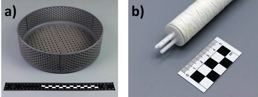
PROCESS ENGINEERING
binder jetting with a silicon melt, e.g., has
been used for some years to produce high
temperature components [13]. The contain
ers shown in Fig. 1 a are fabricated in the
same way. The advantage of melt infiltration
is the avoidance of shrinkage and sintering
distortions. It is especially useful for green
parts with low sintering activity, as they are
typical for binder jetting. Melt infiltration
processes can be optimised by in situ meas
urement and FE simulations as well [14].
5 Final inspection of
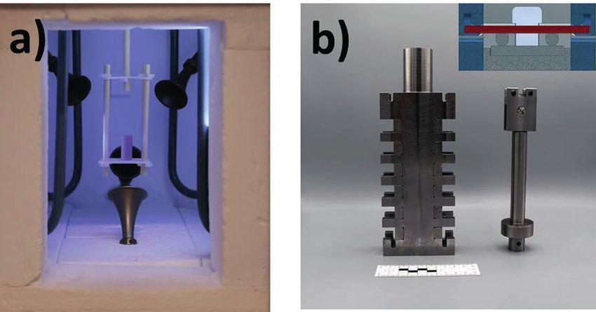
Fig. 6 a–b Non-standard equipment required for data acquisition of debinding
AM components
optimisation: a) thermooptical measuring furnace equipped with weight sensor, bells for Dimensional inspection is one of the most
sound emission measurement and an optical beam path for dimension measurement; important tasks in quality control of AM
b) multi-sample-holder for 4-point bending strength tests on six partially debinded parts. However, compared to customary
specimens measuring, it becomes more difficult when
dealing with complex structures with cav
Specific thermooptical measuring (TOM) A validation of the methodology as stated ities etc. CT can be used as a universal tool
furnaces are used to measure larger above was already published previously for dimensional control, independently of
samples and to obtain other quantities [8], and examples for 3D-printing will be structural constraints. In using special algo
(Fig. 6 a). TOM methods are also relevant published soon. The methodology is con rithms, the deviation between actual geom
for the validation of simulations by sound sidered powerful, since it can be applied etry and target geometry can be quantita
emission measurements, sensitively detect to any shape, once the model with the tively measured.
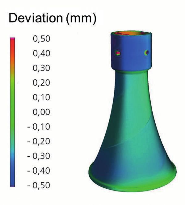
ing cracks in the samples during the thermal parametrized material data has been set up. Fig. 7 shows as an example a sintered
cycle. Additional material properties have to If the shape is simple and component di acoustic bell out of alumina for sound
be measured to obtain a sufficient data mensions are small, simplified methods are emission measurements produced by vat
base for a realistic simulation of debinding available. They are based on a formal kinetic photopolymerisation (compare section 4).
(compare Fig. 5). approach for debinding and need much less Sintering deformations were calculated ac
A delicate task is the mechanical testing of experimental and numerical effort [9, 10]. cording to section 4. Deviations are indicat
partially debinded samples, since they are However, for more complicated parts these ed by a colour code. From this, key figures
very fragile. A multi-sample-holder (Fig. 6 b) simple methods cannot identify optimum for quality control and process optimisation
and highly sensitive load cell are used to debinding conditions. The effort in obtain can be derived. Likewise, internal defects
measure these samples at different tem ing additional data for the accurate model can be detected. The measured structures –
peratures. rapidly pays off, if different components are including large defects – are transferred to
manufactured from the same feedstock. FE models where loads are applied to check
A similar approach, i.e. an experiment- for significant impairments of application
based continuum FE model, has also been properties.
developed for the simulation of sintering. Frequently, attractive sculptures are printed
Input data for sintering are shrinkage, ther as demonstrators for the capability of AM
mal diffusivity and viscous material prop (Fig. 8 a). However, they are rarely suited
erties. Again, special TOM furnaces were for a quantitative comparison of dimen
developed to obtain these data [11]. The sional tolerances. Instead, test geometries
FE model combines temperature field, sin are proposed, for which CAD files can be
tering kinetics and mechanical stresses. It downloaded on the internet [15]. These
also considers gravity and friction, which is test structures are designed for the evalu
important for sintering of 3D-printed parts. ation of thin walls, stairs, angles, needles,
A detailed description of the model and its holes etc. within 3D-printed structures. As
validation was published recently [12]. an example, Fig. 8 b shows an alumina test
Sometimes, in order to obtain dense parts, structure printed by vat photopolymerisa
the infiltration of the porous compacts tion simultaneously checking several struc
Fig. 7 Difference between set geometry with a melt is an interesting alternative to tural features.
and final shape of an alumina bell sintering. Thereby, the melt is soaked into The surface roughness of AM parts can be
(height 54 mm) produced by vat the pore channels by capillary forces. The critical due to stress concentration and also
photopolymerisation infiltration of SiC parts manufactured by for aesthetic reasons. It can be measured
E 48 cfi/Ber. DKG 97 (2020) No. 3-4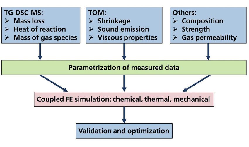
PROCESS ENGINEERING
by laser scanning microscopy nearly inde
pendently of the surface shape. At the HTL,
in-house software is used to extract several
key figures to estimate local stress concen
tration. As with CT data, the surface scans
can be transferred to FE models, in which
they are evaluated in terms of allowed
stresses. If surfaces are not smooth enough
or dimensional tolerances are very strict,
machining is unavoidable. For that purpose,
Fig. 8 a–b Alumina components made by vat photopolymerization: a) sculpture of Rich-
automated machining centres with five axes ard Wagner, a famous composer from the city of Bayreuth; b) standard test geometry
are available which can adjust freeform sur
faces to set shapes.
6 Future trends
In addition to product quality, costs are a
key performance indicator for use of AM in
ceramic production. They are affected by
throughput and production time. The bottle
neck for throughput usually are the prepar
ation of the printing process, the 3D-print
ing process itself and the post-processing of
the parts. Since the subsequent heat treat
ment can be performed in large furnaces
handling many parts in parallel, it usually
doesn’t affect throughput.
On the other hand, the limiting factor for
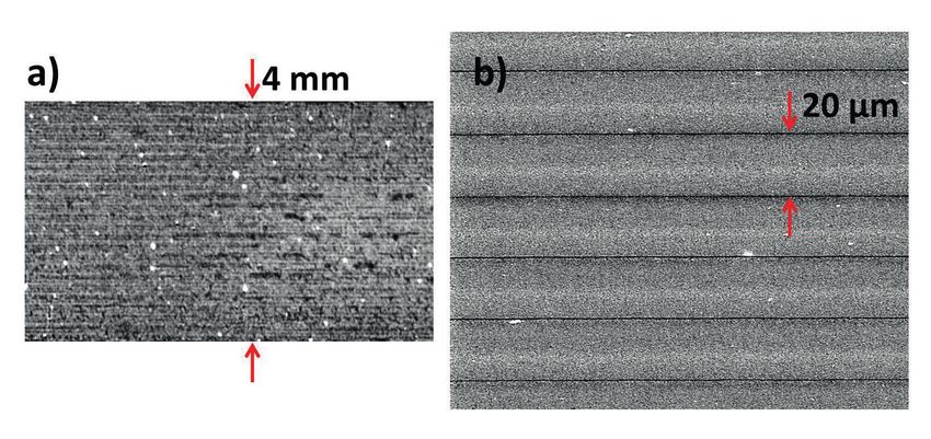
Fig. 9 Setup of a FFS printer at the HTL and schema illustrating the FFS printing process
production time often is the heat treatment,
especially when long debinding steps are
required. Production time is an important nificantly reduced by process automation ited by sintering, where a careful adaption
issue for production on demand, allowing and the integration of the respective equip- of shrinkage properties is required. Other
new business models with higher added ment. wise problems occur, which are well known
value. New AM methods arise with an increasing from the co-firing of multilayer structures. It
Optimisation of debinding as outlined in frequency. Among them, two step methods is estimated that the initial enthusiasm and
chapter 4 is essential for utilising this po based on ceramic slurries are most relevant the current disillusion with respect to intro
tential. Avoiding costly finishing processes for ceramic production. Slurries enable duction of AM in ceramic production will be
by net shape printing and sintering pro small particles and particle mixtures and replaced by selective use of AM in custom
cesses is a cost-relevant topic as well. The lead to relatively high green densities. Up ized production of small series. AM meth
sintering optimisation methods indicated in to now, the highest resolution is obtained ods and printers can be carefully selected
chapter 4 can be used to minimise shape using two-photon polymerization [16] and according to the specific production task.
deviations. Other important cost factors are highest homogeneity was measured with The growth rate of AM in ceramic produc
raw materials. local electrophoretic deposition [17]. tion will be controlled by quality and cost of
Today, feedstocks for 3D-printing are much The latter requires a lot of work for practical AM processes.
more expensive than standard raw mater use, yet. Layerwise Slurry Deposition (LSD)
ials. Recycling of unused feedstock is an [2] and Free Flow Structuring (FFS) [18] are Acknowledgement
important cost factor in all powder bed promising slurry based processes, which can The authors gratefully acknowledge the
based AM methods. Depreciation is another be used for larger components. Fig. 9 shows help of T. Martini, M. Stepanyan, M. Römer
important cost factor in ceramic AM. an FFS-printer for free-flow-deposition of a and T. Kreutzer for help with the measure
Typically, 3D-printers cost several hundreds ceramic slurry on a dried powder bed. LSD ments.
of thousand euros. Nevertheless, there is a and FFS can be used for multi-material
strong trend to smaller and cheaper devices printing, e.g. by adding other materials via References
allowing more flexibility. Many printers are an additional print head. [1] Chen, Z.; et al.: 3D printing of ceramics – a
already available in a price range of some Multi-material printing is also an advantage review. J. of the Europ. Ceram. Soc. 39 (2019)
thousands of euros. Both the costs and re of ink jet printing processes, which showed 661–687
liability of the printing process, as well as rapid progress in terms of resolution [19]. [2] Zocca, A.; et al.: Additive Manufacturing of
the pre- and post-processing can be sig However, AM of multi-material parts is lim Ceramics: Issues, Potentialities, and Opportun
cfi/Ber. DKG 97 (2020) No. 3-4 E 49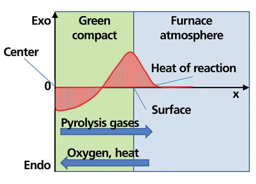
PROCESS ENGINEERING
ities. J. of the Amer. Ceram. Soc. 98 (2015) reduction of debinding processes by combined printing-in-a-completely-new-dimension
1983–2001 in situ measurements and simulation. cfi/Ber. [14] Hofbauer, P.J.; Rädlein, E.; Raether, F.: Finite
[3] Thompson, M.K.; et al.: Design for addi DKG 95 (2018) [1–2] E 37–E 40 elem
ent modeling of reactive liquid silicon
tive manu
facturing: Trends, opportunities, [9] Raether, F.; Klimera, A.: Methods of measure infiltration. J. of the Europ. Ceram. Soc. 40
considerations, and constraints. CIRP Annals ment and strategies for binder removal in cer (2020) [2] 251–258
– Manufacturing Technol. 65 (2016) 737–760 amics. In: Thermal process engineering in the [15] www.nist.gov and VDI 3405 3.2
[4] Website of the VDI guideline 3405, www.vdi. cer
amics industry; M. Herrmann, R. Clasen [16] Houbertz, R.; et al.: Two-photon polymeriza
de/3405, requested on 27.11.2019. (eds.), Göller Verlag, Baden Baden 2008, 5–11 tion of inorganic-organic hybrid polymers
[5] Raether, F.: Energy efficiency during produc [10] Raether, F.: The kinetic field – a versatile tool as scalable technology using ultra-short la
tion of ceramics. cfi/Ber. DKG 90 (2013) [10] for prediction and analysis of heating process ser pulses, Coherence and Ultrashort Pulse
E 27–E 30 es. High Temperatures – High Pressures 42.4 Laser Emission. Tech (2010) 583–608;
[6] Nachum, S.; Vogt, J.; Raether, F.: Additive (2013) 303–319 DOI:10.5772/13203
manufacturing of ceramics: Stereolithography [11] Raether, F.: Current state of in-situ measuring [17] Vogt, L.; et al.: Usability of electrophoretic
versus binder jetting. cfi/Ber. DKG 93 (2016) methods for the control of firing processes. J. deposition for additive manufacturing of ce
[3] E 27–E 33 of the Amer. Ceram. Soc. 92 (2009) 146–152 ramics. Ceramics Int. 45 (2019) 14 214–14
[7] Raether, F.; Schulze Horn, P.: Investigation of [12] Raether, F.; Seifert, G.; Ziebold, H.: Simulation 222
sintering mechanism of alumina using kinetic of sintering across scales. Advanced Theory [18] US6596224 B1: Jetting layers of fine powder
field and master sintering diagrams. J. of the and Simulations 2 (2019) [7] and the formation of fine powder beds there
Europ. Ceram. Soc. 29 (2009) 2225–2234 [13] www.schunk-carbontechnology.com/en/tech by. Sachs et al., 2003
[8] Ziebold, H.; Raether, F.; Seifert, G.: Radical time nologies/stories/current-topics/intrinsicr-3d- [19] www.xjet3d.com
E 50 cfi/Ber. DKG 97 (2020) No. 3-4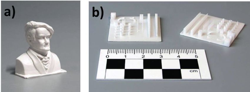
You can also read