Overlapping two standing-waves in a microcavity for a multi-atom photon interface
←
→
Page content transcription
If your browser does not render page correctly, please read the page content below
Overlapping two standing-waves in a
                                                 microcavity for a multi-atom photon interface
                                                 S ÉBASTIEN G ARCIA , 1,2,† F RANCESCO F ERRI , 1,3 J AKOB R EICHEL , 1
                                                 AND R OMAIN L ONG 1,*
                                                 1 Laboratoire Kastler Brossel, ENS-Université PSL, CNRS, Sorbonne Université, Collège de France, 24 rue
                                                 Lhomond, 75005 Paris, France
                                                 2 Present address: Young Physics team’s, Institute of Physics, Collège de France, 11 place Marcelin
arXiv:2003.02731v1 [physics.optics] 5 Mar 2020

                                                 Berthelot, 75005 Paris, France
                                                 3 Present address: Institute for Quantum Electronics, ETH Zürich, 8093 Zürich, Switzerland
                                                 † sebastien.garcia@college-de-france.fr,* long@lkb.ens.fr

                                                 Abstract: We develop a light-matter interface enabling strong and uniform coupling between
                                                 a chain of cold atoms and photons of an optical cavity. This interface is a fiber Fabry-Perot
                                                 cavity, doubly resonant for both the wavelength of the atomic transition and for a geometrically
                                                 commensurate red-detuned intracavity trapping lattice. Fulfilling the condition of a strong and
                                                 uniform atom-photon coupling requires optimization of the spatial overlap between the two
                                                 standing waves in the cavity. In a strong-coupling cavity, where the mode waists and Rayleigh
                                                 range are small, we derive the expression of the optimal trapping wavelength taking into account
                                                 the Gouy phase. The main parameter controlling the overlap of the standing waves is the relative
                                                 phase shift at the reflection on the cavity mirrors between the two wavelengths, for which we
                                                 derive the optimal value. We have built a microcavity optimized according to these results,
                                                 employing custom-made mirrors with engineered reflection phase for both wavelengths. We
                                                 present a method to measure with high precision the relative phase shift at reflection, which
                                                 allows us to determine the spatial overlap of the two modes in this cavity.

                                                 1.   Introduction
                                                 The development of light-matter interfaces has played a key role in the progress achieved
                                                 in laser physics, nonlinear optics and quantum optics. In recent years, the emergence of
                                                 quantum technologies underlines the need of developing new interfaces for applications ranging
                                                 from quantum communication to quantum metrology. In Cavity Quantum Electrodynamics
                                                 (CQED) [1], the light-matter coupling is enhanced by placing emitters inside a cavity. One
                                                 prominent milestone in this field has been the achievement of the strong coupling regime between
                                                 a single emitter and a cavity mode [2–8].
                                                    Focusing on atomic systems, single atoms strongly coupled to a cavity are envisioned as the
                                                 elementary nodes of future quantum networks [9, 10]. The interaction between a cold atomic
                                                 ensemble and a cavity mode in the weak coupling regime at the single atom level has led to the
                                                 generation of multiparticle entangled states useful for metrology [11–13]. Light matter interfaces
                                                 have also been pushed to explore the regime where each atom of an atomic ensemble is strongly
                                                 coupled to the cavity mode. This allows to engineer a strong controllable effective coupling
                                                 between the atoms mediated by the cavity field, enabling the generation of specific multiparticle
                                                 entangled states [14, 15] and the simulation of many-body models [16–19].
                                                    For experiments with many atoms, the question arises on how to implement a strong and yet
                                                 uniform coupling between the cavity mode and each atom of the atomic ensemble, which requires
                                                 that all the atoms interact with the same maximal value of the cavity field. To implement this
                                                 condition, one approach is to minimize the size of the atomic sample by using Bose-Einstein
                                                 Condensates (BEC) and loading the BEC inside a single antinode of the cavity mode [20, 21].
This method is very effective for generating collective interaction but it is not compatible with
single particle detection and control, which has emerged as a powerful tool in the fields of trapped
ions [22], Rydberg atoms [23] and ultracold atoms in optical lattices [24]. In the context of
CQED, single atom addressability has only been realized in systems with two atoms [15, 25].
   In order to combine single particle resolution and a strong uniform coupling of each atom
with the cavity mode resonant with the atomic transition, we use the spatial periodicity of the
standing waves of linear Fabry-Perot cavity modes. By precisely positioning single atoms at
different antinodes of the cavity mode, we can obtain a one-dimensional array of single atoms
with maximal uniform coupling and single particle control. To get a stable overlap between the
atoms and the cavity mode at the wavelength λ1 of the atomic transition, we aim to produce such
a chain of atoms by optically trapping the atoms at the antinodes of a second red-detuned cavity
mode at a commensurate wavelength λ2 ' 2λ1 , as presented in Fig. 1. Such a configuration has
been used previously to couple atomic ensemble to a macroscopic cavity in the weak coupling
regime [19, 26–29].
   In this article, we show that extending this scheme to atomic ensembles where each atom is
strongly coupled to the cavity field necessitates a careful maximization of the spatial overlap
between the two standing-waves of the doubly-resonant cavity. We demonstrate how to optimize
this overlap, we present experimental methods to measure it and we apply them to our doubly-
resonant cavity. The overlap is especially critical for CQED experiments in the strong coupling
regime, as they usually require cavities with high finesse and small mode volume, which leads
to the natural choice of microcavities such as fiber Fabry-Perot cavities [30]. For such short
cavities, the Rayleigh range is usually small and so the Gouy phase shift plays a major role. In
addition, the atomic ensemble spreads over a large fraction of the cavity length (on the order
of the Rayleigh length), which imposes special constraints for the optimization. A similar
problematic arises in frequency doubling by using a doubly-resonant cavity, where a good spatial
overlap is also required between the fundamental mode and the second harmonic one [31–34].
But, microcavities are usually not used in this context, which relaxes the need for an advanced
optimization of the overlap.

                           Resonant mode at λ1                  Dipole trap mode at λ2

                  Fiber mirror                            Atoms

       Fig. 1. Schematic view of our multi-atom photon interface in a fiber Fabry-Perot cavity (not
       to scale). The photonic mode (blue) of the quantum interface has a wavelength λ1 close
       to the atomic resonance. A second auxiliary cavity mode (red) with wavelength λ2 ' 2λ1 ,
       red-detuned from atomic resonance, creates an array of microtraps that overlap with each
       second maximum of the field at λ1 . This optimizes the coupling between the atomic array
       and the cavity photons at λ1 .

   In section 2, we analyze theoretically the parameters that affect the overlap and we derive
conditions to optimize it. In particular, we show in the following that the naive condition λ2 = 2λ1
needs corrections due the geometric Gouy phase shift which leads to a non-trivial optimal
wavelength for the trapping light. Given this condition, we demonstrate that the maximal overlap
is obtained for an optimal relative phase shift between the two wavelengths at the reflection on
the cavity mirrors. We illustrate the effect of this optimization by plotting the characteristic
overlap phase and the strength of the coupling between a single atom and a photon for all trapping
positions along the cavity axis. In Sec. 3, we discuss the implementation of the optimal relative
phase on reflection for our dielectric mirror coatings. Then, we report on experimental techniques
which we developed to measure this relative phase. First in Sec. 4, we observe directly the overlap
via the perturbation of the two modes at λ1 and λ2 with a nanoscopic probe and we deduce a
coarse value of the relative phase. Second, in Sec. 5, we present a measurement that allows us to
determine the relative phase with high precision, by measuring the double resonance condition
as a function of the cavity length.
2. Doubly-resonant cavities with maximal spatial overlap of the standing waves
In this first part, we analyze and optimize the parameters that determine the spatial overlap of the
modes in order to maximize it. We consider a linear Fabry-Perot resonator whose geometrical
length is given by L, formed by two identical spherical concave mirrors, i.e. with identical radius
of curvature R and identical coating. This configuration places the waist of the cavity modes
at the center of the resonator and thus maximizes here the coupling to emitters. The following
analysis can be extended to the case of asymmetric cavities where the two mirrors have different
radii of curvature.
2.1. Optimal wavelength
In the simple case of plane waves, the maximal spatial overlap between the standing waves
at λ1 and λ2 is simply obtained by the condition λ2 = 2λ1 . For Gaussian cavity modes, we
only consider in the following the fundamental transverse Gaussian mode TEM00 , so transverse
coordinates are not involved. However, the Gouy phase shift has to be taken into account, which
is the additional phase shift accumulated by a Gaussian beam when passing through its waist
compared to an ideal plane wave. As a consequence, the effective wavelength of the Gaussian
beam around the focus can be significantly different from c/ν, where ν is the laser frequency and
c the speed of light. In order to obtain a maximal spatial overlap between the two wavelengths λ1
and λ2 ≈ 2λ1 , this local variation of the periodicity has to be taken into account to determine the
optimal wavelength. By defining z as the coordinate along the cavity axis and by setting z = 0 as
the position of the cavity waist, the phase
of a mode propagating along the cavity axis is given by
λ z − ΦG (z), where ΦG (z) = arctan zR is the Gouy term with zR = 2 L(2R − L) the Rayleigh
2π z 1
p
length. At the first order, the effective wavelength at the position z is then given by:
−1
1 1 dΦG
λieff (z) = − (z) . (1)
λi 2π dz
A maximal overlap is then obtained by the condition λ2eff (z) = 2λ1eff (z).
This condition cannot be fulfilled for all z because the Gouy term is independent on the
wavelength. By choosing to impose this condition at the waist (z = 0) for a symmetric cavity, we
obtain a relation between the wavelengths of the two modes:
opt 2λ1
λ2 = λ1
. (2)
1+ 2πzR
This simple relation guarantees a quasi-optimal overlap between the two effective wavelengths
over a length smaller or comparable to zR around the waist.
For our specific experiment, λ1 is the wavelength of the laser probe, which is fixed by the
Rubidium atomic transition to 780.24 nm (D2 line of 87 Rb). The cavity mirrors have a radius
of curvature R ' 300 µm and the cavity length is L ' 130 µm. From Eq. 2, we then get
opt
λ2 ' 1558.92 nm, which is significantly different from 2λ1 . This is due to the small value of the
opt
Rayleigh length zR and the difference λ2 − 2λ1 can exceed the tunability range of typical diodelasers. Using this value for λ2 , we also calculate in the extreme off-centered position z = 65 µm,
the ratio λ2eff /λ1eff ' 1.99956, which indicates a good match between the effective wavelengths
over the whole cavity length.
2.2. Doubly-resonant cavities
The cavity has to be simultaneously resonant at the two different wavelengths λ1 and λ2 . The
eigenfrequencies of such a resonator are fixed by the condition that the phase shift accumulated
in one cavity round-trip has to be an integer multiple of 2π:
2L L
2πνqlp − 2φm − 4(l + p + 1)ΦG = 2πq (3)
c 2
where νqlp is the frequency of the eigenmode with longitudinal order q and whose Hermite-Gauss
transverse shape is identified by l and p. As we will focus on the fundamental transverse mode
TEM00 , we set l = p = 0. φm is the phase shift due to the reflection on a mirror,
whose value
is determined by the structure of the reflective coating. ΦG L2 = arctan 2zLR is the Gouy
phase-shift accumulated from the center of the cavity to a mirror. One should note that the
terms φm and ΦG L2 , which are fixed for a given cavity, can significantly affect the resonant
frequencies in the case of microcavities (where q is small).
For a doubly-resonant cavity, the condition of Eq. 3 has to be fulfilled by both wavelengths:
2π L
2L − 2φm1 − 4ΦG = 2πq1
λ1 2
2π L
2L − 2φm2 − 4ΦG = 2πq2 (4)
λ2 2
where we have considered only the fundamental TEM00 modes with longitudinal index q1 for λ1
and q2 for λ2 . φm1 and φm2 represents the phase shifts after a reflection on the mirror for the
wavelengths λ1 and λ2 , respectively.
2.3. Optimal relative phase
The condition λ2eff (z) = 2λ1eff (z) is necessary but not sufficient to obtain a maximal spatial overlap
between the standing waves of the two cavity modes. Indeed, even if the effective wavelengths
λ1eff and λ2eff are commensurate, the relative position of the nodes of the standing waves inside the
cavity is not univocal.
We first consider the simple configuration of a cavity with planar identically-coated mirrors
which forces the condition λ2 = 2λ1 . The symmetry imposes that each standing wave must
have either a node or an antinode in the center of the cavity. Thus, only four configurations
are possible, as shown in Fig. 2. The targeted configurations A and B, where the antinodes
overlap, are only obtained if λ1 has an antinode in the center of the cavity. Whether the nodes of
the standing waves (minimum overlap) or their antinodes (maximum overlap) are coincident is
determined by the relative phase shift at reflection between the two wavelengths. In the following,
we define the relative phase shift as ∆φm = φm2 − φ2m1 . As shown by the difference between the
field intensities on the mirror for λ2 and λ1 , the four configurations have indeed different relative
phase shifts at reflection.
By using the double resonance condition of Eqs. 4, we get the expression of the relative phase
shift at reflection:
φm1
q
1
1 1 L
∆φm ≡ φm2 − =π − q2 + 2πL − − ΦG . (5)
2 2 λ2 2λ1 2A |E|² B |E|²
Mirror
Mirror
C |E|² D |E|²
Fig. 2. Schematic view of the cavity field intensities |E | 2 for the wavelengths λ1 (blue) and
λ2 (red). Assuming that the two wavelengths differ by a factor 2, we show the four possible
spatial configurations (A to D) that are allowed by symmetry in a cavity with planar mirrors.
The four solutions presented in Fig. 2 are defined by the four integer and half-integer values of the
quantity q21 − q2 modulo 2. Indeed, for a cavity with planar mirrors, the last two terms in Eq. 5
cancel because we impose λ2 = 2λ1 from Eq. 2 and ΦG L2 = 0. The configurations presented in
Fig. 2 assume φm1 = π to obtain a node on the mirror, and so q1 + 1 is the number of antinodes of
the standing wave at λ1 in the cavity. Thus, there is an antinode in the center of the cavity when
q1 is even, which corresponds to the configurations A and B. As a consequence, the maximal
overlap of antinodes is obtained for ∆φm = q21 − q2 π with q21 − q2 integer. The solutions with
q1
2 − q2 half-integer lead to overlapping nodes configurations C and D and must be rejected.
We can rewrite Eq. 5 by keeping only the optimal solutions and by reporting the condition for
opt
the wavelength λ2 = λ2 of Eq. 2 to get the optimal relative phase shift in the general case of a
cavity with identical concave mirrors:
opt opt opt L L
∆φm = nπ + δφm , with δφm ≡ − arctan , (6)
2zR 2zR
opt
where n is an integer and where the non-integer part δφm of the relative phase depends only
on two parameters : the cavity length L and the radius of curvature R of the mirrors. This
non-integer part originates from the Gouy phase after compensation of its linear effect by the
opt opt
choice of λ2 . For our specific cavity parameters, we get δφm = +2.4◦ , which is a small value
because the Rayleigh length zR ' 124 µm is on the order of the cavity length L.
The electric field amplitude Ei of the standing-wave at λi (i = 1, 2) on the optical axis z is
proportional to cos (Ψi (z)), where the propagation phase Ψi is given by:
φmi
2π L L
Ψi (z) = z− − ΦG (z) − ΦG + . (7)
λi 2 2 2
Thus, the overlap between the two resonant cavity modes can be quantified by the overlap phase
∆Ψ (z) = 2Ψ2 (z) − Ψ1 (z), which indicates the dephasing between the two standing wave patterns.
Indeed, in case of perfect overlap, at the position of an antinode of the λ2 standing-wave, there is
an antinode of the λ1 standing-wave, which implies that Ψ2 and Ψ1 are zero modulo π, as well
as ∆Ψ. On the contrary, if a node of the λ1 standing-wave is located at an antinode of the λ2standing-wave, the overlap phase is ∆Ψ = ±π/2 modulo π. As we seek to maintain the overlap
over all the antinodes of the λ2 standing-wave, ∆Ψ has to remain close to zero modulo π along
the cavity axis z.
For a given relative phase on reflection ∆φm = nπ+δφm (with n integer and δφm ∈ [−π/2, π/2])
and a given wavelength λ1 , the condition of double resonance of Eqs. 4 imposes the wavelength
λ2 , chosen to satisfy the condition q21 − q2 integer by using q21 − q2 = n in order to be the closest
opt
of the optimal value λ2 given by Eq. 2. By substituting the expressions of λ1 and λ2 in Eq. 7,
we deduce the following expression of the overlap phase between the two resonant cavity modes :
z z
∆Ψ (z) = δφm + nπ + ΦG (L/2) − ΦG (z) . (8)
L/2 L/2
We see in this equation that the overlap phase depends explicitly on δφm and so on the relative
phase. In this equation, the nπ term modulo 2π differentiates between the solutions with antinodes
overlapping at z = 0 (type A in Fig. 2) or at z = λ1eff /2 (type B in Fig. 2) which can both lead to
opt
optimal overlap if δφm = δφm . As the overlap only depends on ∆Ψ modulo π, we consider the
case n = 0, where ∆φm = δφm , for simplicity in the following analysis.
90
ΔΦm - ΔΦmopt :
0 deg. 30 deg.
Overlap phase ΔΨ (deg.)
50 0 deg. x(-20) 60 deg.
15 deg. 90 deg.
0
x(-20)
-50
-90
-60 -40 -20 0 20 40 60
Optical axis, z (µm)
Fig. 3. Overlap phase ∆Ψ between the standing waves at λ1 = 780.24 nm and λ2 along the
cavity optical axis z. Different colors correspond to different relative phases on reflection
opt
∆φm , compared to the optimum value ∆φm . The dashed light purple curve represent the
optimal-phase purple curve multiplied by a factor −20 to enhance the visibility.
In Fig. 3, we plot the overlap phase ∆Ψ (z) for our specific cavity parameters, depending on the
opt
deviation ∆φm − ∆φm from the optimal relative phase at reflection. In the general case where the
relative phase ∆φm is not optimized, the overlap phase is dominated by the first term of Eq. 8 and
we can observe in Fig. 3 a linear variaton of ∆Ψ (z) with a slope proportional to the relative phase
opt
on reflection. At the optimal relative phase ∆φm , the overlap phase ∆Ψ (z) is simply given by
z z
∆Ψ (z) = − arctan + nπ. (9)
zR zR
Around z = 0, the choice of the optimum relative phase cancels at first order the z dependency of
the overlap phase, which remains close to zero over the largest possible cavity length, meaning
that the antinodes of the two standing waves coincide. Even at this optimal relative phase, a
perfect overlap cannot be maintained over the whole cavity range due to the change in effective
wavelengths implied by the Gouy phase. However, in this case, the deviation has a zero derivative
in the center of the cavity.70
Coupling strength, g/2π (MHz)
60
50
40 ΔΦm - ΔΦmopt :
30 0 deg.
15 deg.
20 30 deg.
60 deg.
10 90 deg.
0
-60 -40 -20 0 20 40 60
Optical axis, z (µm)
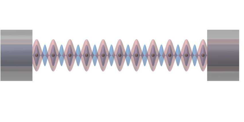
Fig. 4. Coupling strength g/2π between a single atom and a single photon in the cavity
field as a function of the position z of the lattice site where the atom is trapped. Different
opt
colors correspond to different relative phases ∆φm , compared to the optimum value ∆φm .
The coupling has been calculated with: a cavity length L = 130 µm, mirrors with radius of
curvature R = 300 µm, a cavity finesse F780 = 5 · 104 , an intracavity circulating power of
100 mW for the dipole trap creating a maximal depth of 72 µK, and a temperature of the
atom of 10 µK.
2.4. Single atom-photon coupling along the atomic array
In CQED experiments, the strong coupling regime is reached when the single atom - single photon
coupling strength g is larger than the cavity decay rate κ and the atomic one γ. For our specific
atom and cavity, γ/(2π) ' 3 MHz and κ/(2π) ' 15 MHz. For an atom precisely positioned at
an antinode (at the center of the cavity) of the standing wave of the resonant wavelength λ1 , we
calculate the maximal value of the coupling strength gmax /(2π) ' 82 MHz, indicating that our
system operates deeply in the strong coupling regime of CQED.
To underline the need of carefully optimizing the overlap between the standing waves, we
compute the single-atom single-photon coupling strength g at each trapping site (determined
by the antinodes of the standing-wave of the λ2 mode) along the cavity axis z (see Fig.4). The
calculation uses our specific cavity parameters and values of the dipole trap depth and the atom
temperature, that are typically used in experiments. We plot the coupling for different values of
opt
∆φm − ∆φm . At the center of the cavity where the two standing waves are overlapped, the value
of coupling strength g/(2π) ' 67 MHz is reduced compared to the maximal one due to thermal
motion of the atoms in the trap wells, which leads to an averaged value of g.
As the relative phase ∆φm approaches the optimal one, the variation of the coupling along z
becomes dominated by the divergence of the cavity mode at 780 nm, with a coupling difference
between the center and the periphery of the cavity below 15%. In the opposite case, if the
relative phase ∆φm deviates from the optimal one, the coupling decreases strongly while moving
away from the cavity center. In the limit of a 90◦ deviation, the coupling decreases to half of
the maximal value at 40 µm from the center. This underlines the importance of implementing
and verifying experimentally the conditions described above for achieving an optimal overlap
between the cavity standing waves.
3. Dual-wavelength reflective coating
As explained in the previous section, the relative phase at the reflection on a cavity mirror is a
crucial parameter to obtain the maximal overlap. In this section, we discuss the implementation
of the relative phase for the high reflective dielectric coating used for our fiber mirrors [35].
Our mirrors are Bragg reflectors obtained by stacking layers of different dielectric materials,deposited on the end facet of the fiber by ion sputtering. The Bragg structure determines not only
the global reflection and transmission coefficients of the mirrors, but also the relative phase shift
at reflection between λ1 and λ2 , which is essential for the optimal overlap between the standing
waves. The company Laseroptik designed and realized the mirror coating taking into account the
given constraint of the relative phase at reflection. The expected optical properties of our mirrors
solely depend on the thickness and the optical index of the different Bragg layers, resulting in
the optical index profile shown in Fig. 5. We performed a calculation of the optical field based
on the evolution of an incident scalar plane wave in the transfer matrix formalism [36] for each
wavelength λ1 = 780 nm and λ2 = 1559 nm, see Fig. 5.
Cavity Mirror coating Fiber
Field amplitude, |E| (a.u.)
2 2
Optical index, n
1.5 1.5
1 |E780 nm| 1
|E1559 nm|
0.5 n780 nm 0.5
0 0
-2 0 2 4 6 8 10
Optical axis, z (µm)
Fig. 5. Calculation of the mirror properties. The green curve shows the evolution of optical
index n along the optical axis z, inside the dielectric mirror (starting at z = 0, dashed lines
shows the mirror stack limits). The electric field amplitudes |E | of reflected waves at 780 nm
and 1559 nm are represented in blue and red, respectively. They are calculated with transfer
matrix theory from the optical index and assuming an incident wave of amplitude 1.
We observe that the fields decrease quickly while penetrating in the mirror because the layers
reflect progressively the incident wave. From the field energy distribution, we calculate the
optical penetration depths dp,1 ' 1.20 µm and dp,2 ' 1.51 µm, at λ1 = 780 nm and λ2 = 1559 nm,
respectively. The penetration of the field in the mirrors increases the effective optical length of
the cavity Leff = L + 2dp , which defines the free spectral range (FSR) c/2Leff . In the calculations
of the previous sections (Eq. 3 and resulting equations), the propagation phase accumulated
in the penetration depth by the wave is included in the mirror reflection phase φm . By using
the resonance condition of Eq. 3 to calculate the FSR and by linearizing in the FSR expression
the change of the reflection phase φm (λ) with the wavelength λ, the penetration depth can also
λ2
be calculated as dp,i ' 4πi ∂φ m
∂λ (λi ). This calculation of the penetration depth is analytically
equivalent to the one using the energy field distribution for high reflective Bragg mirrors [37].
Indeed, when applied to our calculated mirror phases at λ1 = 780 nm and λ2 = 1559 nm, this
equation yields the same values of penetration depths than the ones obtained from the field energy
distribution.
In Fig. 5, we also directly observe that the field antinodes of the two standing waves have
a very good spatial overlap. From the field calculations, we find that the fields at λ1 and λ2
have reflection phases φm,1 = 207.6◦ and φm,2 = 99.4◦ respectively, and thus a relative phase
∆φm = 0 × π + δφm with δφm = −4.4◦ . This value differs from the optimal value of +2.4◦
calculated above from our cavity parameters. The reason for this discrepancy is incidental and it
originates from a different convention used by the coating company in considering the sign of the
phase. However, this deviation from the optimum is small and thus the overlap is still nearly
optimal, with the coupling strength at each trapping site varying by less than 0.3% from the
values of the optimal relative phase configuration (cf. Fig. 4).In the following paragraphs, we present two methods that allow us to confirm the calculation
by measuring the relative phase shift at reflection between the cavity modes at λ1 and λ2 . The
first one is a direct visualization of the standing waves, allowing to distinguish the configurations
of maximal and minimal overlap (Fig. 2), i.e. to get the integer contribution to ∆φm (modulo 2π).
The second technique consists in a measurement of the precise value of the phase difference by
estimating δφm .
4. Measurement of the overlap of cavity standing waves with a tapered fiber tip
We directly visualize the cavity standing waves with the method described in Ref. [38]. We use a
tapered fiber tip with sub-wavelength apex size to perturb the cavity modes, see Fig. 6(a). We
measure the additional losses induced by the tip from the change of cavity transmission. When
the tip is displaced along the cavity optical axis z, the tip-induced losses change periodically
between a maximum value, when the tip is at the antinodes of the cavity standing waves, and a
minimum value, when the tip is at the nodes. In Fig. 6(b), we show the result of two sweeps of the
tip along a few periods of the standing waves along the cavity axis z: one for each wavelength λ1
and λ2 . The two sweeps are performed at different depth of the tip inside the mode, corresponding
to the two optimal positions for the signal-to-noise, as described in Ref. [38].
a) b)
Tip-induced Losses at 1559nm (ppm)
Tip-induced Losses at 780 nm (ppm)
154 62
Fibers
60
x 152
58
150
z
56
148
54
146
200µm
52
Fiber Tip 144
0 0.2 0.4 0.6 0.8 1 1.2 1.4
Tip position, z (µm)
Fig. 6. (a): Image of the fiber tip inserted in the fiber cavity for the measurement of the
overlap between optical standing waves. (b): Tip-induced cavity losses (data points) at λ1
and λ2 as a function of the tip position z along the cavity axis. The solid curves are best-fit
sinusoids.
In Fig. 6(b), the maxima of the losses at λ1 and λ2 coincide, which is the signature that
the spatial configuration of the standing waves is the one maximizing the overlap between the
antinodes ( q21 − q2 integer), and not the one where the nodes are coincident ( q21 − q2 half-integer).
The sinusoidal fit functions give the difference between the fitted positions of the antinodes at
λ2 and λ1 of about 1 nm, which is below the uncertainty of our alignment procedure of about
±30 nm [38]. Knowing that the tip was positioned at about 40 µm from the center of the cavity
and that increasing z corresponds to a movement towards the mirror, we obtain a rough estimation
of the relative phase shift at the reflection:
∆φm = nπ + δφm with n integer and δφm = (−1 ± 25)◦ . (10)
A complementary measurement, presented in the next section, allows us to estimate δφm with a
much better precision, using the result obtained here that n is an integer.
5. Precise measurement of the relative phase shift at reflection
We implement a method for measuring with a better precision the relative phase shift δφm .
The procedure consists in measuring the laser frequency ν2 = c/λ2 for which the cavity issimultaneously resonant at ν2 and at ν1 = c/λ1 (which is kept fixed) for different cavity lengths.
As we will show in the following, the variation of the laser frequency ν2 (L) as a function of the
cavity L depends strongly on the relative phase at reflection.
Starting from the condition of simultaneous resonance of Eq. 4, we divide by 2 the equation
for λ1 and subtract it from the one for λ2 , we obtain:
2L ν1
2L L q
1
2πν2 = 2π + 2ΦG + 2∆φm − 2π − q2 . (11)
c c 2 2 2
By inserting in this equation, the relative phase as ∆φm = nπ + δφm with n integer or half-integer
and δφm ∈ [−π/4, π/4]) , we obtain:
ν1
c 1 L c q
1
ν2 (L) = + ΦG + δφm + n− − q2 (12)
2 2L π 2 2L 2
In this expression, the last term, which contains the nπ-term of the relative phase, cancels because
experimentally we choose q21 − q2 = n such that the frequency ν2 is the closest possible to ν1 /2
opt
to get λ2 ' λ2 ' 2λ1 . Due to this effect, the measurement method, we will present below, only
allows to determine the value of non integer part δφm of the relative phase. As we know from the
fiber tip measurement presented before that n is an integer, we can determine unambiguously
∆φm modulo π, and so the overlap between the coupling and trapping standing waves. Without a
direct measurement of the standing waves overlap, this method can still be used in combination
with a calculation of the optical field taking account the parameters of the Bragg layers of the
mirrors (see Sect. 3).
By writing explicitly the expression of the Gouy phase and the Rayleigh length, we find:
r ! !
ν1 c 1 L
ν2 (L) = + arctan + δφm (13)
2 2L π 2R − L
This variation of the frequency ν2 necessary to maintain the double resonance condition while
keeping ν1 fixed is plotted in Fig. 7(a) as function of the cavity length L for different values of
δφm . We clearly observe that small differences in the value of δφm lead to strongly different
curves, thus allowing for high precision measurement of the relative phase shift at reflection.
Experimentally, the frequency ν1 = 384.228 THz is fixed by tuning a 780 nm laser diode to
a given transition of a saturated-absorption spectroscopy signal of the rubidium D2 line. The
frequency ν2 of a 1559 nm laser diode is controlled by adjusting the current or the temperature
of the laser diode. To observe the cavity resonances, we measure the cavity transmission while
modulating the cavity length with an amplitude of approximately λ1 with a piezoelectric actuator.
At the double resonance, both transmissions of the 780 nm laser and 1559 nm laser are maximum
for the same voltage on the piezoelectric actuator. In order to reach this situation, we adjust
the frequency ν2 of the 1559 nm laser to the closest double resonance from ν1 /2. Starting with
a cavity length of approximately 150 µm, the length L of the cavity is progressively reduced
by a micrometric screw with a resolution of ±0.5 µm. At every step, ν2 is tuned in order to be
simultaneously resonant with ν1 . In order to know the frequency ν2 of the 1559 nm laser, we
interpolate the values of ν2 provided by a spectrometer for different values of the current and the
temperature, with a relative precision estimated to be 1.4 GHz. We repeat this procedure up to
reach the shortest accessible value of the cavity length.
We obtain the data presented in Fig. 7(b), that we fit with the model of Eq. 13, knowing the
average measured radius of curvature of the mirrors R ' 300 µm. Systematic errors on the
measured values of the laser frequency ν2 and of the cavity length L are taken into account
by adding offsets that are free parameters for the fitting function ν2 (L + δL) + δν2 where ν2 is
given by Eq. 13. The resulting fitted values δν2 ' 3.6 GHz and δL ' 2.2 µm are well below the193 192.36
Frequency of 1559-nm laser, ν2 (THz)
Frequency of 1559-nm laser, ν2 (THz)
45° a) b)
192.8 30°
15° 192.34
192.6 5° Data
Fit
0° 192.32
192.4
-5°
192.2 192.3
-15°
192
-30° 192.28
191.8 -45°
191.6 192.26
0 20 40 60 80 100 120 140 0 20 40 60 80 100 120 140
Cavity length, L (µm) Cavity length, L (µm)
Fig. 7. Resonant frequency ν2 of the 1559 nm laser for which the cavity is simultaneously
resonant at ν1 (fixed to rubidium D2 line), as a function of the cavity length L. (a):
Theoretical curves given by Eq. 13 for different values of δφm (indicated in degree next
to the curve). (b): Experimental data (black points) and best-fit curve (red) obtained with
Eq. 13. The error bars on the frequency (±1.4 GHz) represent the precision of our laser
frequency calibration; the precision of the relative cavity length of ±0.5 µm is not shown.
accuracies of the spectrometer of 60 GHz and of the cavity length estimation of 5 µm, respectively.
As these additional fit parameters only lead to linear displacements of the curve, they do not
affect the determination of the relative phase δφm which controls the shape of the curve.
For our cavity, the phase δφm is slightly negative; thus, in the expression of ν2 (see Eq. 13),
the term in δφm /L is negative whereas the Gouy phase term is positive. The term in δφm /L
determines the divergence of ν2 when√L goes to zero, because it dominates the Gouy phase term
which asymptotically diverges as 1/ L when L
R. Thus, with our small negative relative
√ in Fig. 7(b) when the cavity length tends to zero, the frequency ν2 is first dominated by a
phase,
1/ L asymptotic behavior that leads to an increase towards higher values originating from the
Gouy phase term, but eventually ν2 diverges to smaller values of ν2 due to the δφm /L term.
From the fit, we find that the relative phase shit at reflection is δφm = (−4.9 ± 0.1)◦ . This
value is in good agreement with the calculation based on the coating properties, from which
it deviates by only half a degree. We emphasize the excellent uncertainty of 0.1◦ obtained by
our measurement method, which is a consequence of the high precision of the laser frequency
measurement and of the translation stage that adjusts the cavity length.
6. Conclusion
In this article, we optimize the spatial overlap between commensurate standing waves in a
doubly-resonant cavity. We derive two conditions that have to be fulfilled to optimize this
overlap. First, the effective wavelength (including the Gouy phase) of the trapping lattice has
to be commensurate with the effective wavelength of the mode that is strongly coupled to the
atoms. This implies that the wavelength λ2 of the trapping mode has to fulfill Eq. 2. We note that
such an optimization is possible because we have some freedom in the choice of the the trapping
wavelength λ2 , as opposed to frequency doubling experiments. Second, the antinodes of the two
standing waves have to coincide, which is critically linked to the relative phase shift ∆φm at the
reflection on the cavity mirrors. We calculate the expression of Eq. 6 of the optimal value of
∆φm as a function of the cavity parameters.
The relative phase is controlled by the design of the dielectric mirror and can be calculated with
standard transfer matrix calculations. In order to experimentally check the overlap and measure
∆φm , we develop a two step method. First, the visualization of the optical field distribution withthe fiber tip gives a direct measurement of the spatial overlap, which allows us to verify that the
maxima of the cavity fields (and not the minima) are matched. Second, this result is completed
by a more precise characterization of the relative phase, and therefore of the spatial overlap, by
measuring the frequency ν2 (L) of the dipole laser which satisfies the double resonance condition
as a function of the cavity length L.
Using this procedure, we could demonstrate that a nearly-optimal spatial overlap is achieved in
our cavity. This is a critical requirement to produce new atom-photon interfaces, where a strong
and uniform coupling between the resonant cavity mode and each atom of the array is combined
with single particle control. The spacing between trapping sites is indeed large enough to be
resolvable by a high numerical aperture lens as described in Ref. [38]. This opens the way to new
CQED experiments, where collective operations mediated by the cavity and local operations
on each site of the lattice can be used to generate and study multi-particle entanglement. Such
experiments can address the generation and characterization of entangled states delocalized
over the entire atomic array, useful for multiparameter quantum-enhanced sensing [39, 40]. The
control of a single atom of the array can be used to generates Schrödinger cat-state [41] or to
perform controlled-string operation [42]. Finally, the control over the local coupling at each site
between the atoms via the cavity field enable the simulation of specific spin models [19, 43].
Funding
This work was supported by :
Agence Nationale de la Recherche (ANR) (SAROCEMA project, ANR-14-CE32-0002); European
Research Council (ERC) under the European Union’s Horizon 2020 research and innovation
programme Grant agreement No 671133 (EQUEMI project); and the DIM SIRTEQ from Région
Ile-de-France.
Acknowledgments
The authors acknowledge Pierre-Antoine Bourdel for careful reading of the manuscript and
Tobias Gross (Laseroptik) for fruitful interaction and expert advice.
References
1. S. Haroche and J.-M. Raimond, Exploring the Quantum: Atoms, Cavities, and Photons (Oxford University Press,
2006).
2. D. Meschede, H. Walther, and G. Müller, “One-Atom Maser,” Phys. Rev. Lett. 54, 551–554 (1985).
3. G. Rempe, H. Walther, and N. Klein, “Observation of quantum collapse and revival in a one-atom maser,” Phys. Rev.
Lett. 58, 353–356 (1987).
4. M. Brune, F. Schmidt-Kaler, A. Maali, J. Dreyer, E. Hagley, J. M. Raimond, and S. Haroche, “Quantum Rabi
Oscillation: A Direct Test of Field Quantization in a Cavity,” Phys. Rev. Lett. 76, 1800–1803 (1996).
5. R. J. Thompson, G. Rempe, and H. J. Kimble, “Observation of normal-mode splitting for an atom in an optical
cavity,” Phys. Rev. Lett. 68, 1132–1135 (1992).
6. J. P. Reithmaier, G. Sek,
˛ A. Löffler, C. Hofmann, S. Kuhn, S. Reitzenstein, L. V. Keldysh, V. D. Kulakovskii, T. L.
Reinecke, and A. Forchel, “Strong coupling in a single quantum dot–semiconductor microcavity system,” Nature 432,
197–200 (2004).
7. T. Yoshie, A. Scherer, J. Hendrickson, G. Khitrova, H. M. Gibbs, G. Rupper, C. Ell, O. B. Shchekin, and D. G. Deppe,
“Vacuum Rabi splitting with a single quantum dot in a photonic crystal nanocavity,” Nature 432, 200–203 (2004).
8. A. Wallraff, D. I. Schuster, A. Blais, L. Frunzio, R.-S. Huang, J. Majer, S. Kumar, S. M. Girvin, and R. J. Schoelkopf,
“Strong coupling of a single photon to a superconducting qubit using circuit quantum electrodynamics,” Nature 431,
162–167 (2004).
9. S. Ritter, C. Nölleke, C. Hahn, A. Reiserer, A. Neuzner, M. Uphoff, M. Mücke, E. Figueroa, J. Bochmann, and
G. Rempe, “An elementary quantum network of single atoms in optical cavities,” Nature 484, 195–200 (2012).
10. J. Gallego, W. Alt, T. Macha, M. Martinez-Dorantes, D. Pandey, and D. Meschede, “Strong Purcell Effect on a
Neutral Atom Trapped in an Open Fiber Cavity,” Phys. Rev. Lett. 121, 173603 (2018).11. M. H. Schleier-Smith, I. D. Leroux, and V. Vuletić, “States of an Ensemble of Two-Level Atoms with Reduced
Quantum Uncertainty,” Phys. Rev. Lett. 104, 073604 (2010).
12. R. McConnell, H. Zhang, J. Hu, S. Ćuk, and V. Vuletić, “Entanglement with negative Wigner function of almost
3,000 atoms heralded by one photon,” Nature 519, 439–442 (2015).
13. O. Hosten, N. J. Engelsen, R. Krishnakumar, and M. A. Kasevich, “Measurement noise 100 times lower than the
quantum-projection limit using entangled atoms,” Nature 529, 505–508 (2016).
14. G. Barontini, L. Hohmann, F. Haas, J. Esteve, and J. Reichel, “Deterministic generation of multiparticle entanglement
by quantum Zeno dynamics,” Science 349, 1317–1321 (2015).
15. S. Welte, B. Hacker, S. Daiss, S. Ritter, and G. Rempe, “Cavity Carving of Atomic Bell States,” Phys. Rev. Lett. 118,
210503 (2017).
16. K. Baumann, C. Guerlin, F. Brennecke, and T. Esslinger, “Dicke quantum phase transition with a superfluid gas in an
optical cavity,” Nature 464, 1301–1306 (2010).
17. M. Landini, N. Dogra, K. Kroeger, L. Hruby, T. Donner, and T. Esslinger, “Formation of a spin texture in a quantum
gas coupled to a cavity,” Phys. Rev. Lett. 120, 223602 (2018).
18. R. M. Kroeze, Y. Guo, V. D. Vaidya, J. Keeling, and B. L. Lev, “Spinor Self-Ordering of a Quantum Gas in a Cavity,”
Phys. Rev. Lett. 121, 163601 (2018).
19. E. J. Davis, G. Bentsen, L. Homeier, T. Li, and M. H. Schleier-Smith, “Photon-Mediated Spin-Exchange Dynamics
of Spin-1 Atoms,” Phys. Rev. Lett. 122, 010405 (2019).
20. Y. Colombe, T. Steinmetz, G. Dubois, F. Linke, D. Hunger, and J. Reichel, “Strong atom–field coupling for
Bose–Einstein condensates in an optical cavity on a chip,” Nature 450, 272–276 (2007).
21. F. Brennecke, T. Donner, S. Ritter, T. Bourdel, M. Köhl, and T. Esslinger, “Cavity QED with a Bose–Einstein
condensate,” Nature 450, 268–271 (2007).
22. R. Blatt and D. Wineland, “Entangled states of trapped atomic ions,” Nature 453, 1008–1015 (2008).
23. S. de Léséleuc, V. Lienhard, P. Scholl, D. Barredo, S. Weber, N. Lang, H. P. Büchler, T. Lahaye, and A. Browaeys,
“Observation of a symmetry-protected topological phase of interacting bosons with Rydberg atoms,” Science 365,
775–780 (2019).
24. W. S. Bakr, J. I. Gillen, A. Peng, S. Fölling, and M. Greiner, “A quantum gas microscope for detecting single atoms
in a Hubbard-regime optical lattice,” Nature 462, 74–77 (2009).
25. R. Reimann, W. Alt, T. Kampschulte, T. Macha, L. Ratschbacher, N. Thau, S. Yoon, and D. Meschede, “Cavity-
Modified Collective Rayleigh Scattering of Two Atoms,” Phys. Rev. Lett. 114, 023601 (2015).
26. G. Vrijsen, O. Hosten, J. Lee, S. Bernon, and M. A. Kasevich, “Raman Lasing with a Cold Atom Gain Medium in a
High-Finesse Optical Cavity,” Phys. Rev. Lett. 107, 063904 (2011).
27. K. J. Arnold, M. P. Baden, and M. D. Barrett, “Self-Organization Threshold Scaling for Thermal Atoms Coupled to a
Cavity,” Phys. Rev. Lett. 109, 153002 (2012).
28. J. Lee, G. Vrijsen, I. Teper, O. Hosten, and M. A. Kasevich, “Many-atom–cavity QED system with homogeneous
atom–cavity coupling,” Opt. Lett. 39, 4005 (2014).
29. A. J. Kollár, A. T. Papageorge, K. Baumann, M. A. Armen, and B. L. Lev, “An adjustable-length cavity and
Bose–Einstein condensate apparatus for multimode cavity QED,” New J. Phys. 17, 043012 (2015).
30. D. Hunger, T. Steinmetz, Y. Colombe, C. Deutsch, T. W. Hänsch, and J. Reichel, “A fiber Fabry–Perot cavity with
high finesse,” New J. Phys. 12, 065038 (2010).
31. A. Ashkin, G. Boyd, and J. Dziedzic, “Resonant optical second harmonic generation and mixing,” IEEE J. Quantum
Electron. 2, 109–124 (1966).
32. L.-A. Wu and H. J. Kimble, “Interference effects in second-harmonic generation within an optical cavity,” J. Opt.
Soc. Am. B 2, 697 (1985).
33. R. Paschotta, K. Fiedler, P. Kürz, and J. Mlynek, “Nonlinear mode coupling in doubly resonant frequency doublers,”
Appl. Phys. B 58, 117–122 (1994).
34. M. Liscidini and L. Claudio Andreani, “Second-harmonic generation in doubly resonant microcavities with periodic
dielectric mirrors,” Phys. Rev. E 73, 016613 (2006).
35. S. Garcia, F. Ferri, K. Ott, J. Reichel, and R. Long, “Dual-wavelength fiber Fabry-Perot cavities with engineered
birefringence,” Opt. Express 26, 22249 (2018).
36. S. A. Furman and A. V. Tikhonravov, Basics of Optics of Multilayer Systems (Atlantica Séguier Frontières, 1992).
37. D. I. Babic and S. W. Corzine, “Analytic expressions for the reflection delay, penetration depth, and absorptance of
quarter-wave dielectric mirrors,” IEEE J. Quantum Electron. 28, 514–524 (1992).
38. F. Ferri, S. Garcia, M. Baghdad, J. Reichel, and R. Long, “Mapping optical standing-waves of an open-access
fabry-perot cavity with a tapered fiber,” Rev. Sci. Instrum. (accepted for publication) (2020).
39. T. Baumgratz and A. Datta, “Quantum Enhanced Estimation of a Multidimensional Field,” Phys. Rev. Lett. 116,
030801 (2016).
40. M. Gessner, L. Pezzè, and A. Smerzi, “Sensitivity Bounds for Multiparameter Quantum Metrology,” Phys. Rev. Lett.
121, 130503 (2018).
41. C. C. Gerry and R. Grobe, “Generation and properties of collective atomic schrödinger-cat states,” Phys. Rev. A 56,
2390–2396 (1997).
42. L. Jiang, G. K. Brennen, A. V. Gorshkov, K. Hammerer, M. Hafezi, E. Demler, M. D. Lukin, and P. Zoller, “Anyonic
interferometry and protected memories in atomic spin lattices,” Nat. Phys 4, 482–488 (2008).43. G. Bentsen, T. Hashizume, A. S. Buyskikh, E. J. Davis, A. J. Daley, S. S. Gubser, and M. Schleier-Smith, “Treelike
Interactions and Fast Scrambling with Cold Atoms,” Phys. Rev. Lett. 123, 130601 (2019).You can also read