PQ-Transformer: Jointly Parsing 3D Objects and Layouts from Point Clouds
←
→
Page content transcription
If your browser does not render page correctly, please read the page content below
PQ-Transformer: Jointly Parsing 3D Objects and Layouts from Point
                                                                         Clouds
                                                                         Xiaoxue Chen1 , Hao Zhao2 , Guyue Zhou1 and Ya-Qin Zhang1

                                            Abstract— 3D scene understanding from point clouds plays                (denoted as quads) equations representing structure elements
                                         a vital role for various robotic applications. Unfortunately, cur-         (wall, floor and ceiling). Although these quads are of zero
                                         rent state-of-the-art methods use separate neural networks for             width in nature, we set their widths to a small value for better
                                         different tasks like object detection or room layout estimation.
                                         Such a scheme has two limitations: 1) Storing and running                  visualization, as illustrated by flat blue boxes in Fig. 1(c). By
                                                                                                                    comparing to the ground truth in Fig. 1(b), PQ-Transformer
arXiv:2109.05566v1 [cs.CV] 12 Sep 2021

                                         several networks for different tasks are expensive for typical
                                         robotic platforms. 2) The intrinsic structure of separate outputs          successfully addresses both tasks with high accuracy. Such
                                         are ignored and potentially violated. To this end, we propose              a joint prediction of 3D objects and layouts is favorable for
                                         the first transformer architecture that predicts 3D objects and            many robotics applications, since it can largely reduce the
                                         layouts simultaneously, using point cloud inputs. Unlike existing
                                         methods that either estimate layout keypoints or edges, we                 overhead for both storage and inference.
                                         directly parameterize room layout as a set of quads. As such, the             Furthermore, we propose a new loss function by introduc-
                                         proposed architecture is termed as P(oint)Q(uad)-Transformer.              ing the physical constraints of two tasks during training. This
                                         Along with the novel quad representation, we propose a tailored            loss function originates from a natural supervision signal,
                                         physical constraint loss function that discourages object-layout           instead of the human annotated supervisions. Specifically,
                                         interference. The quantitative and qualitative evaluations on
                                         the public benchmark ScanNet show that the proposed PQ-                    the interference between object boxes and layout quads
                                         Transformer succeeds to jointly parse 3D objects and layouts,              are penalized. On one hand, this is consistent with human
                                         running at a quasi-real-time (8.91 FPS) rate without efficiency-           commonsense and incorporating the constraint makes the
                                         oriented optimization. Moreover, the new physical constraint               learning system closer to the human cognitive system. On
                                         loss can improve strong baselines, and the F1-score of the                 the other hand, since trivial mistakes like objects sinking
                                         room layout is significantly promoted from 37.9% to 57.9%.
                                         Code and models can be accessed at https://github.com/                     into the grounds are corrected, it is natural to expect a
                                         OPEN-AIR-SUN/PQ-Transformer.                                               more accurate result. Regarding the design of neural network
                                                                                                                    architecture, a transformer is specifically tailored for the joint
                                                                 I. I NTRODUCTION                                   prediction task. Using two backbones is computationally
                                            Recent years have witnessed the emergence of 3D scene                   expensive while using two linear heads leads to contradictory
                                         understanding technologies, which enables robots to under-                 usage on queries. As such, two sets of proposal queries
                                         stand the geometric, semantic and cognitive properties of                  are separately generated for both tasks, striking a balance
                                         real-world scenes, so as to assist robot decision making.                  between efficiency and accuracy.
                                         However, 3D scene understanding remains challenging due                       Benefited from the new representation and network, PQ-
                                         to the following problems: 1) Holistic understanding requires              Transformer achieves superior performance on challenging
                                         many sub-problems to be addressed, such as semantic label                  scenes of the public benchmark ScanNet. It succeeds to
                                         assignment [1], object bounding box localization [3] and                   jointly parse 3D objects and layouts, running at a quasi-
                                         room structure boundary extraction [2] etc. However, current               real-time (8.91 FPS) rate without efficiency-oriented opti-
                                         methods solve these tasks with separate models, which is                   mization. Moreover, the proposed physical constraint loss
                                         expensive in terms of storage and computation. 2) The                      improves strong baselines, and the F1-score of the room
                                         physical commonsense [5] like gravity [6] or interference [7]              layout is significantly promoted from 37.9% to 57.9%. As
                                         between different tasks are ignored and potentially violated,              demonstrated in Fig. 5, the results are useful for both re-
                                         producing geometrically implausible results.                               searchers studying 3D scene understanding and practitioners
                                            Aiming for robust 3D scene understanding, we propose                    building robotics systems. The technical contributions are
                                         PQ-Transformer, the first algorithm that jointly predicts 3D               summarized as follows.
                                         object bounding boxes and 3D room layouts in one forward                     • PQ-Transformer is the first neural network architecture
                                         pass. As illustrated in Fig. 1(a), the input is 3D point cloud of                that jointly predicts 3D objects and layouts from point
                                         a scene reconstructed by SDF-based fusion [8] [9]. Note that                     clouds in an end-to-end fashion.
                                         the RGB values are not the inputs, but used for visualization                • Unlike former room layout estimation methods that
                                         merely. PQ-Transformer predicts a set of 3D object boxes                         predict features for layout keypoints, edges or facets,
                                         with semantic category labels and another set of quadrilateral                   we introduce the quad representation and successfully
                                                                                                                          exploit it for discriminative learning.
                                           1 Institute for AI Industry Research (AIR), Tsinghua University, China
                                                                                                                      • We propose a new physical constraint loss that is
                                         chenxiaoxue,zhouguyue,zhangyaqin@air.tsinghua.edu.cn
                                           2 Intel Labs China, Peking University, China zhao-hao@pku.edu.cn,              tailored for the proposed quad representation, which is
                                         hao.zhao@intel.com                                                               principled, generic, efficient and empirically successful.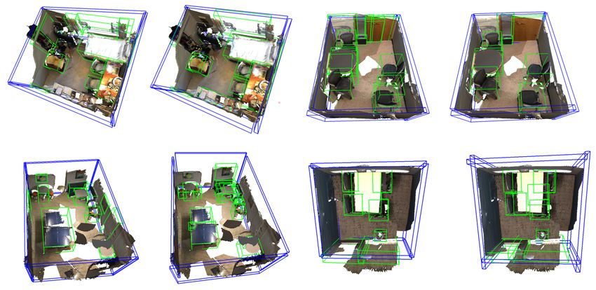
(a) Input Point Cloud                        (b) Ground Truth                         (c) Our Prediction

Fig. 1: Illustration of PQ-Transformer on a representative scene of ScanNet. (a) Input point cloud, where the RGB values
are not the input, but used for visualization merely. Comparing (b) and (c), the proposed PQ-Transformer succeeds to jointly
detect 3D objects (green) and estimates room layouts (blue) in an end-to-end fashion, with high accuracy.

  • PQ-Transformer achieves competitive performance on              PointNet [32]. After looking at aforementioned former arts,
    the ScanNet benchmark. Notably, a new SOTA is                   it is clear that PQ-Transformer is the first transformer-based
    achieved for layout F1-score (from 37.9% to 57.9%).             architecture that jointly predicts 3D objects and layouts from
                                                                    point clouds, with a new quad representation for layouts and
                      II. R ELATED W ORKS
                                                                    its corresponding physical constraint loss.
   Many 3D scene understanding tasks are initially defined
in the image-based setting, before the advent of commod-                                    III. M ETHOD
ity RGB-D cameras. [10] proposes a successful statistical              Our goal is to jointly parse common objects (semantic
feature called geometric context and parses scenes into             labels and 3D bounding boxes) and 3D room layouts with
geometric categories based upon it, which lays the foundation       a single neural network. To this end, we propose an end-to-
for pre-deep-learning data-driven 3D scene understanding.           end attention-based architecture named PQ-Transformer. We
Early works [11] [12] group line segments according to              illustrate our architecture in detail with Fig.2.
Manhattan vanishing points and propose primitives for later            In the remainder of this section, we first introduce a
reasoning, demonstrating the capabilities of estimating room        new representation for 3D room layout, then describe the
layouts. [13] shows that proposing 3D objects aligned to the        detailed network architecture. After that, we propose a novel
Manhattan frame can be used for joint 3D detection and              physical constraint loss to refine the joint detection results,
layout estimation. Later Bayesian models [14] [15] are intro-       by discouraging the interference between objects and layout
duced into the field, which model object-layout relationships       quads. Finally, we discuss the loss function terms to train
as statistical priors in a principled manner. In the last decade,   PQ-Transformer in an end-to-end fashion.
many sub-problems benefit from the strong representation
power of deep neural networks, including but not limited            A. Representation: Layout as Quads
to object detection [16] [17], object reconstruction [18] [19]         The representation for 3D object detection is mature and
and room layout estimation [20] [21] [22] [23]. Recently,           clear. Following former arts [3] [33], we use center coordi-
joint 3D understanding of several sub-tasks has seen exciting       nate, orientation and size to describe an object bounding box.
progress, like COPR [24], Hoslitic++ [25] and Total3D [26].         However, the representation of room layout is still an open
   After the advent of commodity RGB-D sensors like Kinect          problem. Total3D [26] describes the whole room with a 3D
or Realsense, 3D scene understanding with point cloud inputs        bounding box just like objects. However this representation
gradually gains popularity. Since the depth information is          might not work well because the layout of a real-world
readily known, scale ambiguity no longer exists. Yet robust         room is often non-rectangular. Using a single 3D box isn’t
understanding is still challenged by issues like occlusion,         enough to accurately describe it. Like image-based layout
expensive annotations and sensor noise. SlidingShapes [27]          estimation, SceneCAD [2] uses layout vertices and edges as
exploits viewpoint-aware exempler SVMs for 3D detection.            the representation. This representation is not compact and
DeepSlidingShapes [28] designs a sophiscated 3D proposal            requires further fitting to get parametric results.
network with data-driven anchors. Semantic Scene com-                  Different from former methods, we represent the room
pletion [29] [30] jointly completes scenes and assigns 3D           layouts as a set of quads, which is parametric and compact.
semantic labels, taking a single depth image as the input.          Since floors and ceilings are not always rectangular, we only
Point-wise semantic labelling is successsfully addressed by         use quads to represent the walls of a room. Then parametric
recently proposed architectures like SparseConv [31] [1] or         ceiling and floor could be represented by the upper and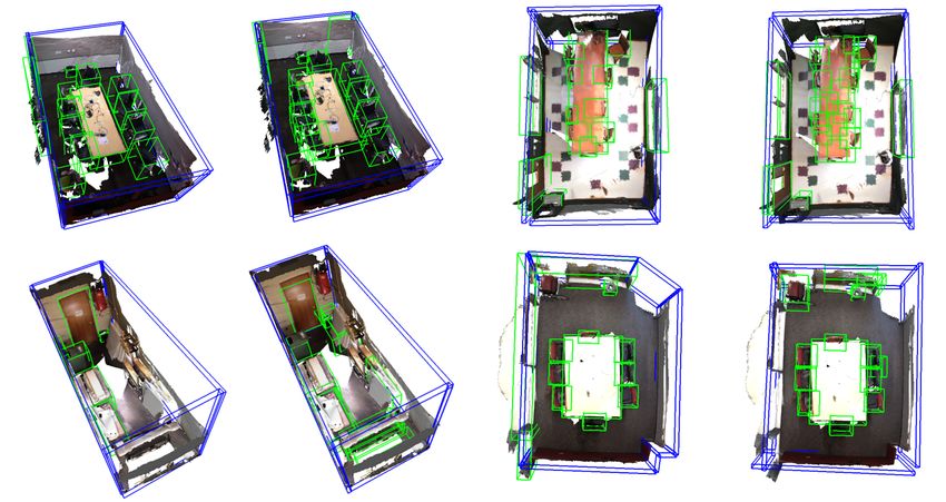
Fig. 2: Overview of PQ-Transformer. Given an input 3D point cloud of N points, the point cloud feature learning backbone
extracts M context-aware point features of (3+C) dimensions, through sampling and grouping. A voting module and a
farthest point sampling (FPS) module are used to generate K1 object proposals and K2 quad proposals respectively. Then
the proposals are processed by a transformer decoder to further refine proposal features. Through several feedforward layers
and non-maximum suppression (NMS), the proposals become the final object bounding boxes and layout quads.

lower boundaries of the walls. In this way, we formulate the     To generate votes, we apply a weight-shared multi-layer
room layout estimation problem into quad detection. Detailed     perceptron (MLP) on fp . The i-th point in fp is represented
mathematical definition can be found in Section III-C.           by feature si = [xi ; fi ], with xi as its 3D point coordinate
                                                                 and fi as its C-dimensional feature. The output of this MLP
B. Network Architecture
                                                                 is offsets of coordinate and feature [∆xi , ∆fi ]. We get its
   The overall network architecture is depicted in Fig.2. It     vote vi = [yi , gi ], where yi = xi + ∆xi and gi = fi + ∆fi .
is composed of four main parts: 1) Backbone: a backbone          We then sample a subset of K1 votes by using an FPS module
to extract features from point clouds; 2) Proposal modules:      on the value of yi . Each cluster is a 3D object proposal.
two proposal modules to generate possible objects and layout
quads respectively; 3) Transformer decoder: a transformer
decoder to process proposal features with context-aware
point cloud features; 4) Prediction heads: two prediction           Farthest Point Sampling. We use FPS to generate K2
heads with several feed forward layers to produce the final      initial proposals for layout quads. FPS is based on the idea of
predictions, in the joint object-layout output space.            repeatedly placing the next sample point in the middle of the
   Backbone. We implement the point cloud feature learn-         least-known area of the sampling domain. FPS starts with a
ing backbone with PointNet++ modules. Firstly, four set-         randomly sampled point as the first proposal candidate, and
abstraction layers are used to down-sample the input 3D          iteratively selects the farthest point from the already selected
point cloud P ∈ R3×N and aggregate local point features.         points until K2 candidates are selected. Though simple,
Then two feature propagation layers are used to up-sample        FPS works well for our layout quad detection formulation.
the points and generate M points with features of dimension      Usually the walls are distributed on the outer boundaries of
C + 3. Concatenated with coordinates, the extracted features     the room and are far from each other. So there is a high
fp ∈ RM ×(C+3) are the context-aware local features of           probability for FPS to select points on the walls that can
the entire scene. It is used as the input to the following       provide good enough proposals for quad detection.
proposal modules and the key of cross-attention layers in
the transformer decoder.
   Proposal modules. We use a voting module and a farthest
point sampling (FPS) module to generate proposals for               Transformer decoder. After generating initial proposals
objects and layout quads, respectively.                          based on voting and FPS, we use a transformer decoder to
   Voting. The idea of voting comes from VoteNet [3], a          further refine the proposal features. The three basic elements
technique based on hough voting. Every point in a bounding       of attention modules are: query (Q), key (K) and value (V ),
box is associated with a voting vector towards the box center.   whose dimensions are all d in our case. Proposal features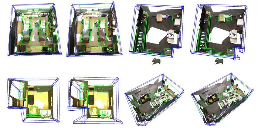
Fig. 3: The conceptual illustration of physical constraint
loss. The left picture is the detection result without physical
constraint loss. As shown in the right picture, after adding
physical constraint loss, the bounding box that intersects the
wall will move inward. As such the detection result will
become more accurate and consistent with physical facts.

                                                                   Fig. 4: The mathematical illustration of physical con-
are denoted as fc . First, we feed fc through self-attention:      straints. We use the vertices of the object bounding box
                                                                   (green) to justify whether it intersects with the wall (blue).
                    Q = K = V = fc                          (1)
                                        T
                                                                   The equation of wall divides the space into two parts. B2 is
                                 QK                                out of the room and B1 is inside the room.
                    A = softmax( √ )                        (2)
                                     d
                    fsa = Psa (AV ) + fc                    (3)
                                                                   to remove duplicate boxes, because we give the quad a fixed
  The self-attention layer exploits the mutual relationship        (but small) width to form a flat cuboid.
between all object and layout quad proposals.
  In addition, we use the context-aware point cloud feature        C. Physical Constraint
fp produced by backbone as the key, and fuse it with the
                                                                      For now, the object and layout outputs of PQ-Transformer
proposal features fsa through cross-attention layers:
                                                                   can take unrealistic values, yet there are physical constraints
                    Q = fsa , K = V = fp                    (4)    between them in real-world rooms. For example, a table
                                 QK    T                           might be near to a wall, but it can never overlap with
                    A = softmax( √ )                        (5)    the wall. In addition, the bottom of the table cannot be
                                     d                             lower than the floor. Based on this fact, we design a novel
                    fca = Pca (AV ) + fsa                   (6)    physical constraint loss tailored for our quad representation
   Here Psa and Pca are fully connected layers with batch          for layouts, in order to discourage interference. It can help
normalization and ReLU. Our transformer decoder has six            the network generate more precise and reasonable results.
blocks, with each one consisted of a self-attention layer and a    It is noteworthy that although there are physical constraints
cross-attention layer. Six blocks generate six sets of detection   between most objects and walls, some types of objects do
results, respectively. The detection results of a previous block   overlap with the walls, such as doors, windows and curtains.
are used as the position encoding into the current block.          Therefore, our physical constraints are only designed for
                                                                   those types of objects which will never overlap with walls.
   Prediction Heads. After feeding the proposals through
                                                                   We use the set Cpc to represent the corresponding object
the transformer decoder, we use two sets of MLPs as two
                                                                   categories. Fig.3 illustrates the role of physical constraints.
prediction heads to generate final results. One is used to
classify objects and regress object bounding boxes, while the         We use a quad in the 3D Euclidean space to represent a
other is used to regress layout quads. For object detection,       wall, and the quad defines a 3D plane whose equation is:
we follow the formulation of VoteNet [3], using a vector                                ax + by + cz + d = 0                       (7)
of size 2 + 3 + H + H + S + 3S + C, which consists of 2
objectness scores, 3 center regression values, H heading bins,        Vector (a, b, c) is exactly the normal vector of the plane.
H heading regression values, S size bins, 3S size regression       For dis-ambiguity, we make all normal vectors point to the
values for height-width-depth, and C semantic categories.          center of the room manually. We could divide the 3D space
For layout quad detection, we use a vector of size 10 which        into two parts using this plane. For a point with coordinate
is composed of 2 quadness scores, 3 center regression values,      (x0 , y 0 , z 0 ), if ax0 + by 0 + cz 0 + d > 0, the point is at the
2 size regression values and 3 normal vector components.           same side of the room center, otherwise, the point is out of
Both 3D objects and 2D quads are processed with 3D NMS             the room. Fig.4 illustrates the situation that a bounding box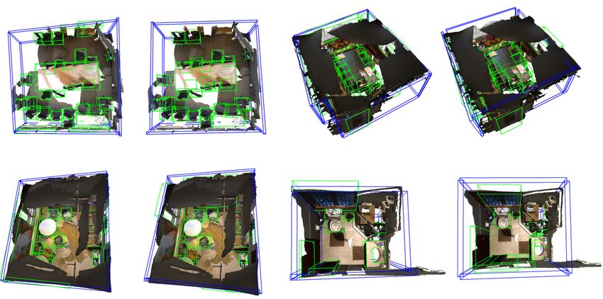
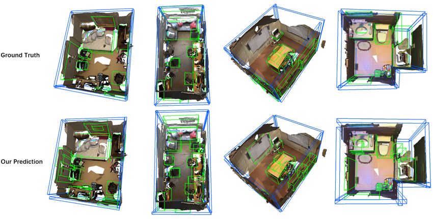
Fig. 5: Qualitative prediction results on ScanNet. Objects are outlined in green while layout quads are outlined in blue.

(green) intersects with a wall (blue, right) and vertice B1 is        D. Loss
in the room while vertice B2 is out of the room. For a 3D                First we denote the layer number of transformer decoder as
object box, we traverse its eight vertices, determine whether         L. We get L+1 sets of detection results in total. Specifically,
they intersect the walls using the plane equations.                   L sets are generated from L layers of the decoder and one set
   For a vertice (xi , yi , zi ), the physical constraint loss we     is generated from the proposal module. Then we calculate
minimize takes the form of ReLU[−(axi + byi + czi + d)].              loss on each set of results and use the summation as the final
However, imposing this loss on all objects and walls might            loss. Losses on intermediate decoder outputs and proposal
cause wrong constraints. For example, in the left part of             module output play the role of auxiliary supervision, which
Fig.3, wall W1 and sofa S1 should not constrain each                  help PQ-Transformer converge. Let the loss of the i-th set
other since the bounding box of S1 and the quad of W1                 of detection results be Li , the total loss used in training is:
actually do not intersect. But if we impose the loss equation                                                     L+1
above between W1 and S1 , it leads to a no-zero physical                                                      1 X
                                                                                  Ltotal = Lpc + Lvote +              Li          (9)
constraint loss. To avoid this kind of wrong constraints, we                                                L + 1 i=1
first determine whether the projection of a bounding box
vertice is within the wall quad before calculating the physical         Here Lvote is the loss for voting vectors:
constraint loss. We project the vertice onto the wall plane,
                                                                                        M
and compare its projection with the quad size. The loss                              1 X
equation for a set of detection results with K1 objects and                Lvote =         k∆xi − ∆x∗i k1[si on object]          (10)
                                                                                     M i=1
K2 quads is:
                                                                      Here ∆x∗i is the ground truth voting vector. 1[si on object]
          K1 K2 X
                8
          X  X                                                        indicates whether the point si is inside a bounding box. If it
Lpc =                      ReLU [−(aj xip + bj yip + cj zip + dj )]   is, the value is 1, otherwise it is 0. For each set of results:
          i=1 j=1 p=1
        Ci ∈Cpc
                                                                                          Li = Lobject + Lquad                   (11)
        1[Πqj (xip , yip , zip ) in qj ]                       (8)
                                                                      Lobject is the loss between predicted bounding boxes and
   q denotes a quad. Πqj means the operator projecting a              ground truth boxes, while Lquad is the loss between predicted
point onto the plane that qj defines. Ci means the sementic           quads and ground truth quads. They are calculated as below:
class of object i and Cpc is the set of object classes to                       Lobject = λ1 Lobjectness + λ2 Lbox + λ3 Lcls     (12)
calculate physical constraint loss. The plane equation of j-th
quad is aj x+bj y+cj z+d = 0 and 1[Πqj (xip , yip , zip ) in qj ]
                                                                           Lquad = λ4 Lquadness + λ5 Lquad center
indicates whether the projection of vertice (xip , yip , zip ) is
in qj : if it is, return 1; otherwise, return 0.                                   + λ6 Lquad normal vector + λ7 Lquad size      (13)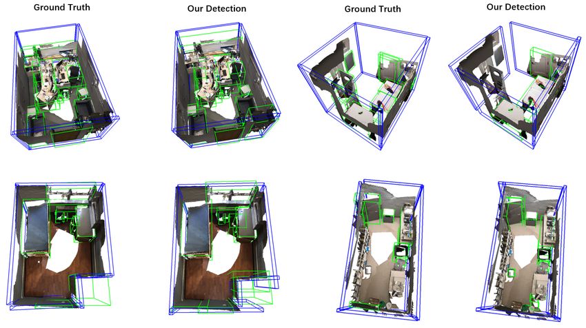
of 40 cm from any ground truth corner. Similarly, predicted
                                                                   polygons are considered correct if composed by the same
                                                                   corner set as any ground truth polygon. As shown in the
                                                                   Tab.I, the room layout F1-score on ScanNet is significantly
                                                                   promoted from 37.9% to 57.9%. And if only considering
                                                                   wall quads, the F1-score is 70.9%. For joint detection, the
                                                                   F1-score also outperforms previous state-of-the-art by 17.9%.

                                                                        TABLE I: Layout estimation results on ScanNet.

                                                                             Method        F1-score (all)    F1-score (wall only)
                                                                            SceneCAD           37.9                   \
                                                                           Ours (joint)        55.8                  68.7
                                                                           Ours (single)       57.9                  70.9

                                                                      3D object detection. We compare our 3D object detection
Fig. 6: Qualitative comparisons on ScanNet. After adding           results with previous state-of-the-arts in Tab.VI. L6 means 6
the physical constraint loss, the bounding boxes no longer         attention layers and O256 means 256 proposals. HGNet [35]
overlap with the walls (left), and the wrongly predicted           exploits a graph convolution network based upon hierarchical
bounding box disappears (right).                                   modelling, for 3D detection. VoteNet [3] uses point-wise
                                                                   voting vectors to generate object proposals. Group-Free [33]
                                                                   is an attention-based detector that generates object proposals
λ1 ∼ λ7 are loss weight parameters. We use cross entropy           with k-nearest point sampling. GSDN [37] uses a fully
loss for all classification results like Lobjectness and Lcls .    convolutional sparse-dense hybrid network to generate the
For regression results like Lquad center and Lquad size , we       support for object proposals. H3DNet [36] predicts a diverse
use smooth L1 loss. Detailed loss weight settings can be           set of geometric primitives and converts them into object pro-
found in the supplementary material.                               posals. Following the standard evaluation protocol, we use
                                                                   mean Average Precision (mAP) to evaluate PQ-Transformer
                      IV. E XPERIMENT
                                                                   on object detection. Tab.VI shows that our approach performs
A. Comparisons with State-of-the-art Methods                       comparable with the state-of-the-art methods.
   Evaluation Details. We validate PQ-Transformer on the
                                                                       TABLE II: 3D object detection results on ScanNet.
widely-used indoor scene dataset ScanNet [34]. It contains
∼1.2K real-world RGB-D scans collected from hundreds of                                  Method                 mAP@0.25
different rooms. It is annotated with semantic and instance                            VoteNet [3]                58.7
segmentation labels for 18 object categories. In addition,                             HGNet [35]                 61.3
                                                                                       GSDN [37]                  62.8
SceneCAD [2] introduces a new dataset by adding 3D                                    H3DNet [36]                 67.2
layout annotations to ScanNet, allowing large-scale data-                       Group-Free [33] (L6, O256)        67.3
driven training for layout estimation. The SceneCAD layout                        Ours (joint, L6, O256)          66.9
                                                                                 Ours (single, L6, O256)          67.2
dataset contains ∼13.8k corners, ∼20.5K edges and ∼8.4K
polygons. We first preprocess these annotations, choosing
polygons which have 4 vertices and nearly horizontal normal
vectors as the ground truth of wall quads during training.         B. Ablation Study
We use the official ScanNet data split. In later paragraphs           Physical constraint loss. To investigate the necessity
and tables, single means that we train object detector and         of physical constraint loss, we train two models with and
layout estimator separately, and joint represents our full PQ-     without it. We demonstrate the results in Tab.III. The mAP
Transformer architecture illustrated in Fig. 2.                    of object detection rises from 64.4% to 66.9% after adding
   Layout estimation. We show our layout estimation results        physical constraint loss and the F1-score of layout estimation
on ScanNet in Tab. I. SceneCAD [2] uses a bottom-up                increases from 54.7% to 55.8%, which clearly shows the
pipeline to predict quads hierarchically. Contrasting with         effectiveness of our physical constraint loss. We also show
SceneCAD, our approach generates quad proposals directly           the number of collisions between objects and walls with two
and refines them with transformer. For comparison, we              models in Tab.III. One collision means a vertex of the object
use the same evaluation metrics as SceneCAD does. As               bounding box is out of the room. The sharp drop in the
mentioned before, ceiling and floor polygons (not neces-           number of collisions shows that our physical constraint loss
sarily quads) are generated by connecting the upper and            discourages object-layout interference successfully.
lower boundaries of predicted wall quads (see details in              As demonstrated in Fig.6, the object detection results are
the supplementary material). Polygon corners are considered        more reasonable with physical constraint loss. In the top-
successfully detected if the predicted corner is within a radius   left sample, the bounding box of the toilet in the red box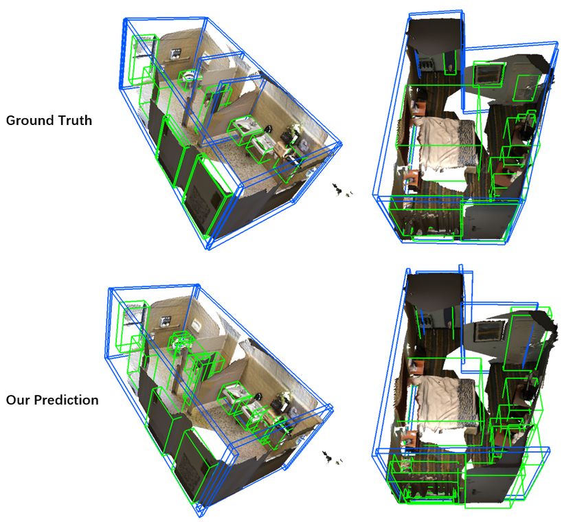
intersects with the wall, which is impossible in the real-
world. While training with the physical constraint loss, this
error no longer exists. In the top-right sample, influenced
by the point cloud outside the room, there is a meaningless
bounding box there when training without physical constraint
loss. And it vanishes after adding the loss.

TABLE III: Joint prediction results on ScanNet with or
without using the physical constraint loss.

               Object (mAP)    Layout (F1-score)    No. Collisions
   w/o Lpc         64.4              54.7               7208
   w/ Lpc          66.9              55.8                 9

   Architecture. Since how to design a single transformer
for two structured prediction tasks remains unclear, we de-
sign experiments to compare several alternative architectures
which are shown in Tab.IV. Joint (one proposal) represents
the model trained with a single proposal module for both
object detection and layout estimation. In this case, our two           Fig. 7: Failure cases on ScanNet. PQ-Transformer fails to
tasks would compete for bottom-up proposals. And our archi-             detect the two partition walls in the middle of the room (left)
tecture depicted in Fig.2 is denoted as joint (two proposals).          and the inclined wall (right).
Tab.IV shows that although single has achieved the best
results, its runtime speed is very slow. Joint (one proposal)
has the best efficiency, but its performance is obviously poor.         approach fails to detect the two partition walls in the middle
Our model has achieved comparable quantitative results with             of the room. And we are unable to detect the inclined wall
single while the speed is close to joint (one proposal). This           on the right side of the room, in the second column.
verifies the effectiveness of our architecture. We believe this
                                                                                                  V. C ONCLUSION
insight is useful for similar multi-task transformer architec-
tures: separating different tasks at the proposal stage, rather             In this study, we develop the first attention-based neural
than inputs or prediction heads.                                        network to predict 3D objects and layout quads simultane-
                                                                        ously, taking only point clouds as inputs. We introduce a
        TABLE IV: Architecture design comparisons.                      novel representation for layout: a set of 3D quads. Along with
                                                                        it, we propose a tailored physical constraint loss function that
      Architecture       Speed (FPS)   Object mAP     Layout F1-score   discourages object-layout interference. A multi-task trans-
          single            4.29          67.2             57.9
  joint (one proposal)      9.52          44.6             52.4         former architecture that strikes the balance between accuracy
 joint (two proposals)      8.91          66.9             55.8         and efficiency is proposed. We evaluate PQ-Transformer on
                                                                        the public benchmark ScanNet and show that: 1) The new
                                                                        physical constraint loss can improve strong baselines. 2) The
C. Qualitative Results and Discussion                                   layout F1-score on ScanNet is significantly boosted from
   Fig.5 shows our joint parsing results on ScanNet. It is              37.9% to 57.9%. We believe our method is useful for robotics
manifest from Fig.5 that our approach can predict the wall              applications as the final model runs at a quasi-real-time (8.91
quads precisely even if the room is non-rectangular and                 FPS) rate without efficiency-oriented optimization.
detect the bounding boxes of most objects successfully.                                             R EFERENCES
The differences between our object detection results and
ground truth mainly arise from annotation ambiguity and                  [1] Avetisyan, A., Khanova, T., Choy, C., Dash, D., Dai, A. and Nießner,
                                                                             M., 2020. SceneCAD: Predicting object alignments and layouts in rgb-
duplicate detection. To be more exact, in the first column                   d scans. In Computer Vision–ECCV 2020: 16th European Conference,
of Fig.5, our approach detects the desk in the bottom-left                   Glasgow, UK, August 23–28, 2020, Proceedings, Part XXII 16 (pp.
corner while it isn’t annotated in the ground truth. And                     596-612). Springer International Publishing.
                                                                         [2] Choy, C., Gwak, J. and Savarese, S., 2019. 4d spatio-temporal con-
in the second column, our approach recognizes the corner                     vnets: Minkowski convolutional neural networks. In Proceedings of the
sofa as two separate sofas while ground truth takes it as                    IEEE/CVF Conference on Computer Vision and Pattern Recognition
a whole one. More qualitative results are provided in the                    (pp. 3075-3084).
                                                                         [3] Qi, C.R., Litany, O., He, K. and Guibas, L.J., 2019. Deep hough
supplementary material. Considering the diversity of these                   voting for 3d object detection in point clouds. In Proceedings of the
scenes, we believe PQ-Transformer is accurate enough for                     IEEE/CVF International Conference on Computer Vision (pp. 9277-
various robotics applications.                                               9286).
                                                                         [4] Hedau, V., Hoiem, D. and Forsyth, D., 2009, September. Recovering
   Our layout estimation approach still has limitations. Fig.7               the spatial layout of cluttered rooms. In 2009 IEEE 12th international
shows some failure cases on ScanNet. In the first column, our                conference on computer vision (pp. 1849-1856). IEEE.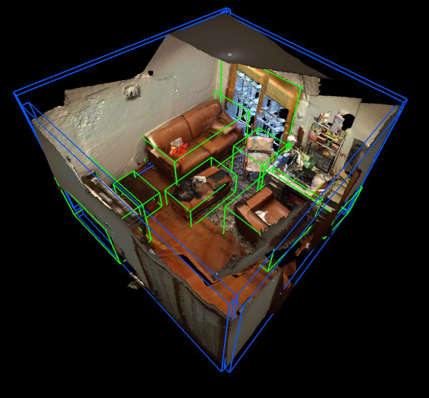
[5] Zhu, Y., Gao, T., Fan, L., Huang, S., Edmonds, M., Liu, H., Gao, F.,               physical commonsense. In Proceedings of the IEEE/CVF International
     Zhang, C., Qi, S., Wu, Y.N. and Tenenbaum, J.B., 2020. Dark, beyond                Conference on Computer Vision (pp. 8648-8657).
     deep: A paradigm shift to cognitive ai with humanlike common sense.         [26]   Nie, Y., Han, X., Guo, S., Zheng, Y., Chang, J. and Zhang, J.J., 2020.
     Engineering, 6(3), pp.310-345.                                                     Total3dunderstanding: Joint layout, object pose and mesh reconstruc-
 [6] Zheng, B., Zhao, Y., Yu, J., Ikeuchi, K. and Zhu, S.C., 2015. Scene                tion for indoor scenes from a single image. In Proceedings of the
     understanding by reasoning stability and safety. International Journal             IEEE/CVF Conference on Computer Vision and Pattern Recognition
     of Computer Vision, 112(2), pp.221-238.                                            (pp. 55-64).
 [7] Fouhey, D.F., Delaitre, V., Gupta, A., Efros, A.A., Laptev, I. and Sivic,   [27]   Song, S. and Xiao, J., 2014, September. Sliding shapes for 3d object
     J., 2014. People watching: Human actions as a cue for single view                  detection in depth images. In European conference on computer vision
     geometry. International journal of computer vision, 110(3), pp.259-                (pp. 634-651). Springer, Cham.
     274.                                                                        [28]   Song, S. and Xiao, J., 2016. Deep sliding shapes for amodal 3d object
 [8] Newcombe, R.A., Izadi, S., Hilliges, O., Molyneaux, D., Kim, D.,                   detection in rgb-d images. In Proceedings of the IEEE conference on
     Davison, A.J., Kohi, P., Shotton, J., Hodges, S. and Fitzgibbon, A.,               computer vision and pattern recognition (pp. 808-816).
     2011, October. Kinectfusion: Real-time dense surface mapping and            [29]   Song, S., Yu, F., Zeng, A., Chang, A.X., Savva, M. and Funkhouser,
     tracking. In 2011 10th IEEE international symposium on mixed and                   T., 2017. Semantic scene completion from a single depth image. In
     augmented reality (pp. 127-136). IEEE.                                             Proceedings of the IEEE Conference on Computer Vision and Pattern
 [9] Han, L. and Fang, L., 2018, June. FlashFusion: Real-time Glob-                     Recognition (pp. 1746-1754).
     ally Consistent Dense 3D Reconstruction using CPU Computing. In             [30]   Zhang, J., Zhao, H., Yao, A., Chen, Y., Zhang, L. and Liao, H.,
     Robotics: Science and Systems (Vol. 1, No. 6, p. 7).                               2018. Efficient semantic scene completion network with spatial group
[10] Hoiem, D., Efros, A.A. and Hebert, M., 2007. Recovering surface                    convolution. In Proceedings of the European Conference on Computer
     layout from an image. International Journal of Computer Vision, 75(1),             Vision (ECCV) (pp. 733-749).
     pp.151-172.                                                                 [31]   Graham, B., Engelcke, M. and Van Der Maaten, L., 2018. 3d semantic
[11] Hedau, V., Hoiem, D. and Forsyth, D., 2009, September. Recovering                  segmentation with submanifold sparse convolutional networks. In
     the spatial layout of cluttered rooms. In 2009 IEEE 12th international             Proceedings of the IEEE conference on computer vision and pattern
     conference on computer vision (pp. 1849-1856). IEEE.                               recognition (pp. 9224-9232).
[12] Lee, D.C., Hebert, M. and Kanade, T., 2009, June. Geometric reason-         [32]   Qi, C.R., Yi, L., Su, H. and Guibas, L.J., 2017. Pointnet++: Deep
     ing for single image structure recovery. In 2009 IEEE conference on                hierarchical feature learning on point sets in a metric space. arXiv
     computer vision and pattern recognition (pp. 2136-2143). IEEE.                     preprint arXiv:1706.02413.
[13] Schwing, A.G., Fidler, S., Pollefeys, M. and Urtasun, R., 2013. Box         [33]   Liu, Z., Zhang, Z., Cao, Y., Hu, H. and Tong, X., 2021. Group-Free 3D
     in the box: Joint 3d layout and object reasoning from single images.               Object Detection via Transformers. arXiv preprint arXiv:2104.00678.
     In Proceedings of the IEEE International Conference on Computer             [34]   Dai, A., Chang, A.X., Savva, M., Halber, M., Funkhouser, T. and
     Vision (pp. 353-360).                                                              Nießner, M., 2017. Scannet: Richly-annotated 3d reconstructions of
[14] Choi, W., Chao, Y.W., Pantofaru, C. and Savarese, S., 2015. Indoor                 indoor scenes. In Proceedings of the IEEE conference on computer
     scene understanding with geometric and semantic contexts. Interna-                 vision and pattern recognition (pp. 5828-5839).
     tional Journal of Computer Vision, 112(2), pp.204-220.                      [35]   Chen, J., Lei, B., Song, Q., Ying, H., Chen, D.Z. and Wu, J., 2020.
[15] Zhao, Y. and Zhu, S.C., 2013. Scene parsing by integrating function,               A hierarchical graph network for 3D object detection on point clouds.
     geometry and appearance models. In Proceedings of the IEEE confer-                 In Proceedings of the IEEE/CVF conference on computer vision and
     ence on computer vision and pattern recognition (pp. 3119-3126).                   pattern recognition (pp. 392-401).
[16] Qin, Z., Wang, J. and Lu, Y., 2019, July. Monogrnet: A geometric rea-       [36]   Zhang, Z., Sun, B., Yang, H. and Huang, Q., 2020, August. H3dnet:
     soning network for monocular 3d object localization. In Proceedings                3d object detection using hybrid geometric primitives. In European
     of the AAAI Conference on Artificial Intelligence (Vol. 33, No. 01,                Conference on Computer Vision (pp. 311-329). Springer, Cham.
     pp. 8851-8858).                                                             [37]   Gwak, J., Choy, C. and Savarese, S., 2020. Generative sparse de-
[17] Huang, S., Chen, Y., Yuan, T., Qi, S., Zhu, Y. and Zhu, S.C., 2019.                tection networks for 3d single-shot object detection. In Computer
     Perspectivenet: 3d object detection from a single rgb image via                    Vision–ECCV 2020: 16th European Conference, Glasgow, UK, Au-
     perspective points. arXiv preprint arXiv:1912.07744.                               gust 23–28, 2020, Proceedings, Part IV 16 (pp. 297-313). Springer
[18] Wu, J., Wang, Y., Xue, T., Sun, X., Freeman, W.T. and Tenenbaum,                   International Publishing.
     J.B., 2017. Marrnet: 3d shape reconstruction via 2.5 d sketches. arXiv
     preprint arXiv:1711.03129.
[19] Chen, Z., Tagliasacchi, A. and Zhang, H., 2020. Bsp-net: Generating
     compact meshes via binary space partitioning. In Proceedings of the
     IEEE/CVF Conference on Computer Vision and Pattern Recognition
     (pp. 45-54).
[20] Mallya, A. and Lazebnik, S., 2015. Learning informative edge maps
     for indoor scene layout prediction. In Proceedings of the IEEE
     international conference on computer vision (pp. 936-944).
[21] Dasgupta, S., Fang, K., Chen, K. and Savarese, S., 2016. Delay: Robust
     spatial layout estimation for cluttered indoor scenes. In Proceedings
     of the IEEE conference on computer vision and pattern recognition
     (pp. 616-624).
[22] Zhao, H., Lu, M., Yao, A., Guo, Y., Chen, Y. and Zhang, L.,
     2017. Physics inspired optimization on semantic transfer features: An
     alternative method for room layout estimation. In Proceedings of the
     IEEE conference on computer vision and pattern recognition (pp. 10-
     18).
[23] Fernandez-Labrador, C., Facil, J.M., Perez-Yus, A., Demonceaux, C.,
     Civera, J. and Guerrero, J.J., 2020. Corners for layout: End-to-end
     layout recovery from 360 images. IEEE Robotics and Automation
     Letters, 5(2), pp.1255-1262.
[24] Huang, S., Qi, S., Zhu, Y., Xiao, Y., Xu, Y. and Zhu, S.C., 2018. Holis-
     tic 3d scene parsing and reconstruction from a single rgb image. In
     Proceedings of the European conference on computer vision (ECCV)
     (pp. 187-203).
[25] Chen, Y., Huang, S., Yuan, T., Qi, S., Zhu, Y. and Zhu, S.C.,
     2019. Holistic++ scene understanding: Single-view 3d holistic scene
     parsing and human pose estimation with human-object interaction and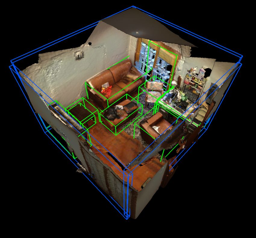
APPENDIX                                  polygon, it is considered successfully estimated.
                                                                     3) Physical Constraint Implementation Details: The com-
A. Method Details
                                                                  putational complexity of the generic physical constraint loss
   This section provides additional implementation details        we introduced in the main paper is high. Because we have
of PQ-Transformer. First, we show network architecture in         to traverse eight vertices of all object bounding boxes and
section A-1 and layout estimation details in section A-2.         all quads. Considering the fact that the wall quads are nearly
Then in section A-3, we discuss our implementation of             vertical, we only calculate a 2D version of physical constraint
physical constraint loss. After that, we elaborate on our         loss in practice to reduce computation. We transform all the
loss weights setting in section A-4. And finally, we provide      bounding boxes and quads into top-down view. Then the
training details in section A-5.                                  bounding boxes become rectangles and the quads become
   1) Architecture Specification Details: The point cloud         line segments. We represent a line segment with equation
feature learning backbone is implemented with modules in          ax + by + d = 0 and a length l. And for a vertice
PointNet++ [1]. It consists of 4 set abstraction layers and       (xi , yi ), the physical constraint loss between it and the
two feature propagation layers. For each set abstraction layer,   line segment becomes ReLU[−(axi + byi + d)]. To further
the input point cloud size is down-sampled to 2048, 1024,         improve efficiency, we accelerate iteration of vertices with
512 and 256 respectively. And the two feature propagation         matrix operations. We use P ∈ Rn×2 to describe n vertices
layers up-sample the point cloud features to 512 and 1024         whose coordinates are of dimension 2. Q = [a, b]T represents
by applying trilinear interpolation on the input features.        the normal vector of the line segment. Π ∈ Rn indicates
   We generate K1 proposals for object detection and K2           whether the projection of vertices are in the line segment.
for layout estimation where K1 = K2 = 256. Then we                The loss between n vertices and the line segment (quad) is:
use a transformer decoder with 6 attention layers to refine
proposals. The head number of it is 8.                                       Lpc = sum (ReLU [−(P Q + d)]              Π)   (14)
   Following [2], we parameterize an oriented 3D bounding            where     denotes element-wise product and sum means
box as a vector of size 2 + 3 + H + H + S + 3S + C.               summation of all elements in the matrix. We compare the
The first two are objectness scores and the next three are        training time of different Lpc implementations of in Tab. V,
center regression results. H is the number of heading bins.       which shows the efficiency of the our implementation.
We predict a classification score and a regression offset for
each heading bin. S is the number of size bins. Similarly,         TABLE V: Time cost for one batch (8 samples) training.
we predict a classification result and three regression results
(height, width and length) for each size bin. And C is the                                              Time cost /s
number of semantic classes. In ScanNet [5], we set H = 12                              w/o Lpc             0.24
                                                                                    w/ Lpc (trivial)       1.77
and S = C = 18.                                                                    w/ Lpc (efficient)      0.32
   2) Layout Estimation Details: Quad NMS and Ceil-
ing/Floor Evaluation: The layout estimation result obtained
by the prediction head contains K2 quads. To remove du-              4) Loss Balancing Details: PQ-Transformer is trained
plicate quads, we give each quad a fixed width to form a          with a multi-task loss in an end-to-end fashion. As mentioned
flat cuboid. In our implementation, we set the width to 10        in the main paper, the object loss Lobject is denoted as:
cm so that we could process these flat cuboids easily with                Lobject = λ1 Lobjectness + λ2 Lbox + λ3 Lcls      (15)
3D NMS. We set the IoU threshold of NMS to 0.25, during
training.                                                         We use the loss weights to balance different loss functions
   Through 3D NMS and quadness filtering (only consider           as follows:
quads with quadness scores >0.5), we get K20 quads. We
                                                                                λ1 = 0.5,      λ2 = 1,      λ3 = 0.1.
use them to generate ceiling and floor. First, We initialize
a list Ec for the ceiling. Then we traverse K20 quads,            The quad loss Lquad is denoted as:
adding the upper edge of the quad into Ec . After that
we iterate through Ec . If the distance between vertices on           Lquad =λ4 Lquadness + λ5 Lquad center
two edges in Ec is less than 40 cm, the two vertices will                      + λ6 Lquad normal vector + λ7 Lquad size     (16)
be merged by averaging. After merging, Ec becomes the
                                                                  And the weights for Lquad are:
edge estimation of the ceiling. which defines a polygon.
The merging procedure is illustrated in Fig 8. Similarly, we                    λ4 = 0.5,       λ5 = λ6 = λ7 = 1.
calculate floor edges using the lower edges of quads in the
same way. As mentioned in the main paper, we use the same         Specifically, the detailed form of Lbox is:
evaluation metrics as SceneCAD [6] does. Two vertices are              Lbox =λ8 Lcenter + λ9 Lhead cls + λ10 Lheading reg
considered the same if they are within 40 cm of each other.
                                                                                + λ11 Lsize cls + λ12 Lsize reg             (17)
And an edge is considered correct if composed by the same
two vertices with any ground truth edge. So if the ceiling or     where Lcenter is loss for bounding box center, Lhead cls is
floor is composed of the same edges with any ground truth         heading bin classification loss, Lheading reg is heading bin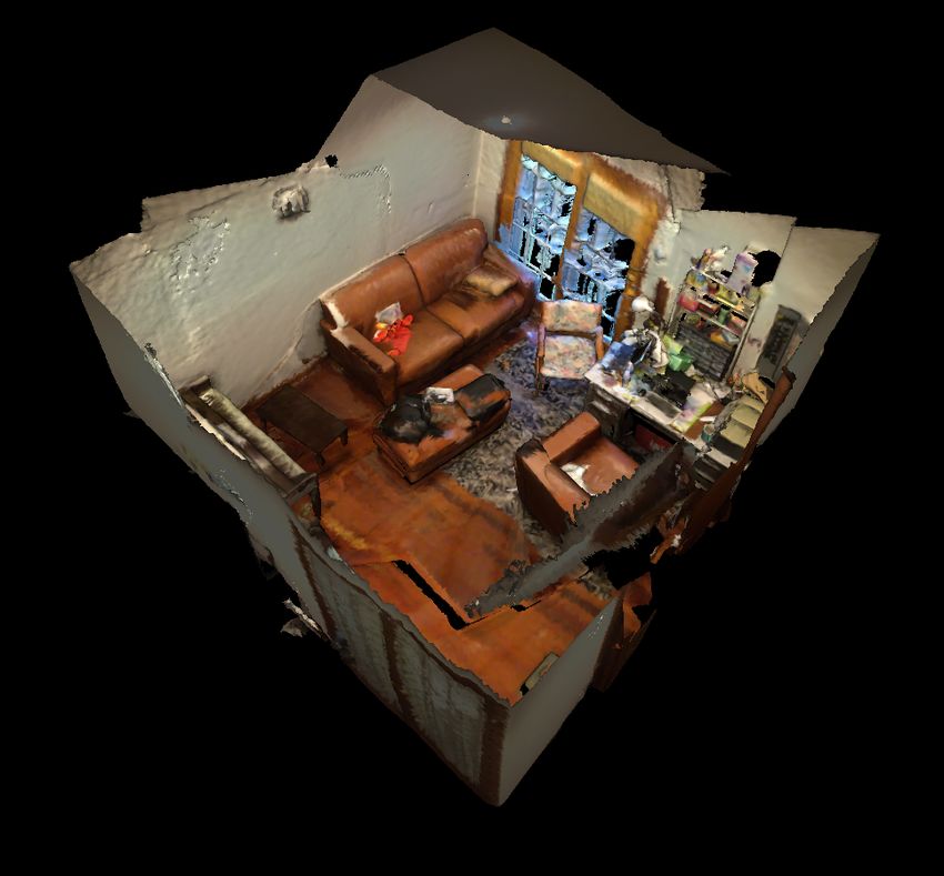
Fig. 8: Illustration of the merging procedure in Ceiling/Floor evaluation.

regression loss, and Lsize cls and Lsize reg are classification
score loss and regression loss for box size bin respectively.
And the weights are as follows:

           λ8 = λ10 = λ12 = 1,           λ9 = λ11 = 0.1.
   5) Training Details: We train PQ-Transformer with with
three NVIDIA GeForce RTX 3090 GPUs and test it on
a single GPU. The network is trained with an AdamW
optimizer in an end-to-end fashion. And we sample 40K
vertices from ScanNet as our input point clouds, setting batch
size per GPU to 8. We spend 600 epochs to train the model.
B. More Qualitative Results
   We show more qualitative results of PQ-Transformer on
ScanNet. The results are shown in Fig.9. Considering the
diversity of scenes and objects in these cases, we believe our
approach has achieved accurate and robust object detection
and layout estimation.
C. ScanNet Per-category Evaluation
  Tab. VI demonstrates per-category average precision on
ScanNet with a 0.25 IoU threshold. It shows that PQ-
Transformer performs comparable with state-of-the-art meth-
ods and performs better in some categories.
                            R EFERENCES
 [1] Qi, C.R., Yi, L., Su, H. and Guibas, L.J., 2017. Pointnet++: Deep
     hierarchical feature learning on point sets in a metric space. arXiv
     preprint arXiv:1706.02413.
 [2] Qi, C.R., Litany, O., He, K. and Guibas, L.J., 2019. Deep hough
     voting for 3d object detection in point clouds. In Proceedings of the
     IEEE/CVF International Conference on Computer Vision (pp. 9277-
     9286).
 [3] Zhang, Z., Sun, B., Yang, H. and Huang, Q., 2020, August. H3dnet:
     3d object detection using hybrid geometric primitives. In European
     Conference on Computer Vision (pp. 311-329). Springer, Cham.
 [4] Liu, Z., Zhang, Z., Cao, Y., Hu, H. and Tong, X., 2021. Group-Free 3D
     Object Detection via Transformers. arXiv preprint arXiv:2104.00678.
 [5] Dai, A., Chang, A.X., Savva, M., Halber, M., Funkhouser, T. and
     Nießner, M., 2017. Scannet: Richly-annotated 3d reconstructions of
     indoor scenes. In Proceedings of the IEEE conference on computer
     vision and pattern recognition (pp. 5828-5839).
 [6] Avetisyan, A., Khanova, T., Choy, C., Dash, D., Dai, A. and Nießner,
     M., 2020. SceneCAD: Predicting object alignments and layouts in rgb-
     d scans. In Computer Vision–ECCV 2020: 16th European Conference,
     Glasgow, UK, August 23–28, 2020, Proceedings, Part XXII 16 (pp.
     596-612). Springer International Publishing.
Fig. 9: More qualitative results.
Fig. 9: More qualitative results (cont.).

                             TABLE VI: Per-category 3D object detection results on ScanNet.

         Method               bathtub     bed     bshelf   cabinet    chair     counter   curtain   desk      door    mAP@0.25
       VoteNet [2]             92.1      87.9      44.3     36.3       88.7      56.1      47.2      71.7     47.3      58.7
       H3DNet [3]              92.5      88.6      54.9     49.4       91.8      62.0      57.3      75.9     55.8      67.2
Group-Free (L6,O256) [4]       92.5      86.2      48.5     54.1       92.0      59.4      64.2      80.4     55.8      67.3
Ours (joint, one proposal)     50.5      79.3      28.3     35.7       75.8      17.5      41.2      60.0     27.8      44.6
  Ours (joint, w/o Lpc )       90.9      89.6      43.0     42.6       87.4      61.4      69.3      77.5     51.7      64.4
       Ours (joint)            90.0      94.4      65.3     55.2       89.5      51.3      58.7      87.5     58.4      66.9
      Ours (single)            88.5      94.4      54.2     50.0       88.2      55.3      64.6      84.3     60.5      67.2
         Method                gbin     picture   fridge    sink     scurtain    sofa      table    toilet   window
       VoteNet [2]             37.2       7.8      45.4     54.7       57.1      89.6      58.8      94.9     38.1
       H3DNet [3]              53.6      18.6      57.2     67.4       75.3      90.2      64.9      97.9     51.9
Group-Free (L6,O256) [4]       55.0      15.0      57.2     76.8       76.3      84.8      67.8      97.6     46.9
Ours (joint, one proposal)     26.1       3.5      28.5     65.3       48.8      76.8      20.6      89.0     28.6
  Ours (joint, w/o Lpc )       45.8      15.5      56.0     64.5       79.0      96.6      47.0      96.3     44.9
       Ours (joint)            53.5      14.9      60.0     62.1       65.4      96.9      54.7      97.6     48.1
      Ours (single)            54.1      21.8      54.2     65.8       81.1      90.0      51.6      98.4     51.9
You can also read