Modification of Mechanical and Electromechanical Resonances of Cellular Ferroelectret Films Depending on the External Load - MDPI
←
→
Page content transcription
If your browser does not render page correctly, please read the page content below
Article

Modification of Mechanical and Electromechanical Resonances
of Cellular Ferroelectret Films Depending on the External Load
Julio Quirce Aguilar and Tomás Gómez Álvarez-Arenas *

                                          ITEFI-CSIC, Serrano 144, 28006 Madrid, Spain; j.quirce@csic.es
                                          * Correspondence: t.gomez@csic.es

                                          Abstract: Ferroelectret films are cellular polymers with electrically charged pores that exhibit pie-
                                          zoelectric response. Among other applications, ferroelectret films have been widely used as active
                                          elements in air-coupled ultrasonic transducers. More recently, they have also been tested in water
                                          immersion. They show a promising wide frequency band response, but a poor sensitivity produced
                                          by the disappearance of the electromechanical resonances. This paper studies in detail the modifi-
                                          cation of FE films response when put into water immersion, both the mechanical and the electrome-
                                          chanical responses (the latter in transmission and reception modes). The lack of electromechanical
                                          thickness resonances when the films are put into water is explained as the result of the different
                                          profile of the modification of the polarization vector along the film thickness imposed by the large
                                          mechanical load produced by the water. This different electromechanical response can also be the
                                          reason for the subtle modification of the mechanical thickness resonances that is also observed and
                                          analyzed.

Citation: Aguilar, J.Q.; Gómez            Keywords: cellular polymers; ferroelectrets; thickness resonances; piezoelectric polymers; ultra-
Álvarez-Arenas, T. Modification of        sonic transduction
Mechanical and Electromechanical
Resonances of Cellular Ferroelectret
Films Depending on the External
Load. Polymers 2021, 13, 3239.            1. Introduction
https://doi.org/10.3390/polym131932
                                                Ferroelectrets are cellular polymer films that contain flattened and elongated pores
39
                                          in the film plane with the capability that these pores can be electrically charged in a stable
                                          way [1,2]. Cellular porous solids are widely found in nature as this is a kind of hierarchical
Academic Editors: Judith Martín-de
León and Victoria Bernardo
                                          structure that provides many different design advantages and offer the possibility of com-
                                          bining different functionalities. They are also commonly found in medicine, both as or-
Received: 30 August 2021                  gans that need to be studied and as a source of inspiration for the design of sensors. [3].
Accepted: 21 September 2021               In addition, programmable materials based on cellular solids have also been proposed to
Published: 24 September 2021              recreate the essential features of biologically self-adaptive materials [4]. As a result of their
                                          cellular structure, ferroelectrets are thin and flexible polymeric films that exhibit piezoe-
Publisher’s Note: MDPI stays neu-         lectric properties. Different manufacturing techniques have been used, such as the two-
tral with regard to jurisdictional        step inflation technique [5], template-patterning techniques [6,7] and additive manufac-
claims in published maps and institu-     turing techniques [8]. This cellular structure is designed so that the deformation of the
tional affiliations.                      material takes place through bending of the pore walls and the possibility of trapping
                                          electrical charge in the pores in a stable way is maximized [9]. This gives rise to very re-
                                          duced elastic modulus, so relatively large deformations can be achieved. This feature to-
                                          gether with the trapped electrical charge in the pore walls gives rise to a macroscopic
Copyright: © 2021 by the authors. Li-
                                          piezoelectric response. Previous studies of ferroelectret materials have been oriented to-
censee MDPI, Basel, Switzerland.
                                          wards characterizing the films, modifying the cellular microstructure to maximize the pi-
This article is an open access article
                                          ezoelectric response and stabilizing and optimizing the electrical charge trapped in the
distributed under the terms and con-
ditions of the Creative Commons At-
                                          pores [5,10–16]. More recently, a new type of material combining conventional piezoelec-
tribution (CC BY) license (http://crea-
                                          tricity (linked to microscopic charge distribution) and ferroelectret piezoelectric response
tivecommons.org/licenses/by/4.0/).

Polymers 2021, 13, 3239. https://doi.org/10.3390/polym13193239                                                 www.mdpi.com/journal/polymers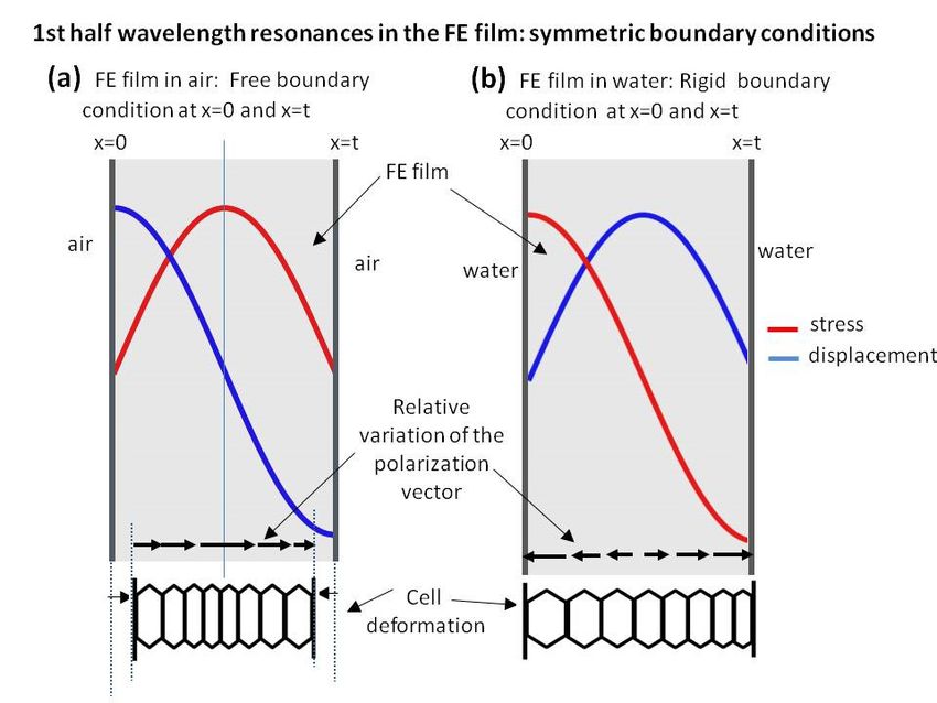
Polymers 2021, 13, 3239                                                                                         2 of 19

                          (linked to macroscopic electrical dipoles trapped in the macroscopic pores) has been pro-
                          posed and used as a biometric sensor [17].
                                Ferroelectrets have been used for many different applications including microphones
                          [18], energy harvesting [19–21], wearable devices [22] and flexible and printable sensors
                          (FLEPS) [23], flexible touch pads and tactile sensors [24], and air-coupled ultrasonic trans-
                          ducers [25–33]. In the latter case, the main advantage is the extremely low acoustic imped-
                          ance of these materials that facilitates the coupling to the air; they are normally operated
                          using the thickness resonances of the films. In addition, the possibility to operate these
                          films in the electrostrictive regime under high voltage excitation offers an important im-
                          provement of transducer efficiency [34,35]. Applications of FE-based air-coupled trans-
                          ducers have mainly been oriented towards non-destructive testing of materials. More re-
                          cently, ferroelectret films have also been revealed as a promising candidate to produce
                          transducers for liquid coupling and hydrophones. Applications in the low frequency
                          range (below 100 kHz) have been studied in [36–38] while applications for wideband ul-
                          trasonic transducer for medical applications and hydrophones, involving a frequency
                          range >200 kHz, have been proposed and studied in [39–41]. They present an extremely
                          wideband response but a very low sensitivity compared with conventional transducers.
                          In addition, they also present some abnormalities compared with the response of FE trans-
                          ducers for air-coupled ultrasonic applications that should be better understood in order
                          to be able to improve their performance in water immersion applications—in particular,
                          to improve sensitivity without compromising the bandwidth and to compensate the sen-
                          sitivity loss when frequency increases.
                                Ref. [42] supposed a step forward, as it showed that air-loaded thickness resonances
                          of these films can be better explained if a sandwich meso-structure together with a cellular
                          microstructure is assumed. This conclusion is consistent with SEM images of the FE film
                          structure. This approach permitted to justify the harmonic distortion of the thickness res-
                          onance spectra observed in these films.
                                The purpose of this paper is to study, simultaneously, both thickness resonances and
                          electromechanical response (both as receiver and transmitter) of this type of material as
                          well as the modifications in both of them when going from the well-known case of air-
                          loaded films to the more unconventional case of water-loaded films, which is of interest
                          for medical transducers and hydrophones, as suggested above. Given that the impedance
                          of these materials is about 0.05 MRayl and impedance of water and air are 1.5 MRayl and
                          4 × 10⁻⁴ MRayl, respectively, the variation of boundary conditions when the film is in water
                          or in air is remarkable.
                                Towards this end, two different FE films have been studied both in air and in water.
                          First, we measured the transmission coefficient in water immersion at normal incidence
                          and for a frequency band that, at least, covers the first order of the thickness resonances—
                          in most cases, the first two orders. Similar measurements were performed in air for the
                          same materials [15,42]; in the latter case, material parameters were extracted by assuming
                          a sandwich structure for the film and solving the inverse problem. Observed resonances
                          in air and in water have been compared and differences have been analyzed.
                                Then, the electromechanical response of the films is measured, both under air and
                          water loads. Two different types of measurements were performed in this case. The first
                          one consists of measuring the generated electric signal in the FE when an ultrasonic signal
                          impinges on the film at normal incidence, while the second one consists of measuring the
                          radiated ultrasonic signal when an electrical excitation is applied to the film (Tx mode).
                          These measurements were performed both in water and in air. Responses of the film un-
                          der these two different loading conditions are compared. Finally, an explanation for the
                          observed differences is provided.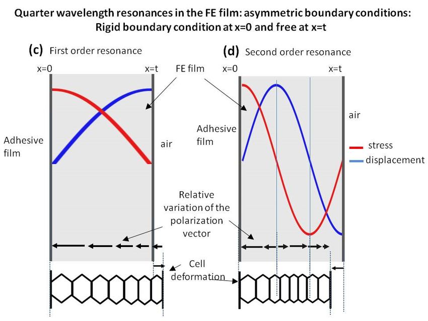
Polymers 2021, 13, 3239                                                                                      3 of 19

                          2. Materials and Methods
                          2.1. Materials
                               Two different ferroelectret (FE) films have been used for this study, both from EMFIT
                          Ltd. (Vaajakoski, FINLAND), commercial names: HS03 and HS06. Properties of these
                          films can be seen in Table 1 and in Refs. [15,41,42].

                          Table 1. Properties of the FE films employed [10].

                                                                          λ/2 Resonant Frequency,
                                           Thickness      Density                                    Impedance
                           Material                                           Thickness Mode
                                             (μm)         (kg/m3)                                     (MRayl)
                                                                                  (MHz)
                             HS03             70             530                   0.638                0.046
                             HS06             90             370                   1.120                0.065

                               To facilitate sample handling and electrical connections for the measurement of the
                          electromechanical response, samples were prepared by sandwiching the FE film between
                          two metallic washers (outer diameter: 40 mm, inner diameter: 25 mm). The FE and the
                          washers were glued using epoxy resin. Once glued, both free surfaces of the FE film and
                          washer were Au sputtered (using a LEICA EM ACE200 sputtering LEICA, Wetzlar, Ger-
                          many), for 60 s) to ensure electrical conductivity between the washer and the surface of
                          the FE film the washer is glued to. Finally, two wires were soldered to the washers and
                          epoxy resin was applied to the edge of the washers and to cover the soldering points as
                          protection and to facilitate the handling of the samples. The structure and composition of
                          the samples so prepared is shown in Figure 1.

                          Figure 1. Schematic representation of the FE film preparation.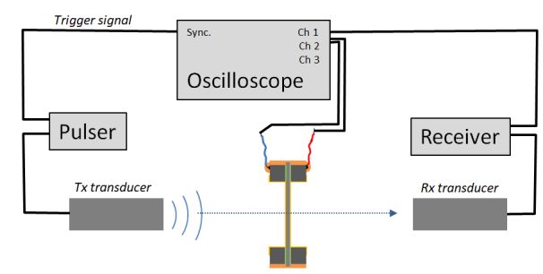
Polymers 2021, 13, 3239 4 of 19
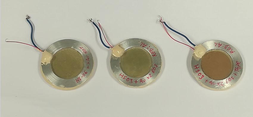
The samples resemble tambourines (see pictures in Figure 2). Two samples using
HS03 film and one sample using HS06 film were prepared. In one of the HS03 samples, a
film of adhesive tape (150 μm thick) was glued to one of the faces of the FE film. Due to
the very small thickness and impedance of the FE film (0.046 MRayl), the presence of this
adhesive tape film is “seen” as very high impedance load (impedance of the adhesive tape
~1.7 MRayl). Hence, the observed thickness resonances of this sample in air are shifted
closer to the quarter wavelength resonances, while for the other samples, we observe the
half wavelength resonances of the free-standing film. On the contrary, when submerged
in water, as the impedance of the water is very close to the impedance of the adhesive
tape, the response of the FE film with the adhesive tape is expected to be very similar to
that of the free film (without adhesive tape).
Figure 2. Picture of the prepared FE films for measurements. The HS03 sample with the adhesive
tape is shown on the right; the brawn adhesive tape can be seen on top of the Au layer.
The experimental set-up is shown in Figure 3. A couple of identical ultrasonic trans-
ducers are positioned in opposition and aligned and the sample to be measured is located
in between them at normal incidence.
Two different media, where both sample and transducers are immersed, have been
used: water and air. When water immersion is used, a small water tank is used as shown
in Figure 4.
(a)Polymers 2021, 13, 3239 5 of 19
(b)
Figure 3. Experimental set-up. (a) Configuration for the measurement of both the transmission co-
efficient and the FE film and the film response in Rx mode; (b) configuration for the measurement
of the FE film response in Tx mode.
Figure 4. Water tank for water immersion measurements.
All measurements were performed at room conditions. For water immersion meas-
urements, a pair of wide band transducers (Olympus, Olympus NDT Inc., Quebec, Can-
ada, Ref #V303, 15 mm diameter, 1 MHz center frequency) have been employed. These
transducers permit to cover the frequency range from 0.2 to 1.4 MHz. In some cases, it
was of interest to expand the frequency range to higher frequencies. In these cases, a sec-
ond pair of transducers, also from Olympus (Olympus NDT Inc., Quebec, Canada), cen-
tered at 2.25 MHz were used (15 mm diameter, Ref #C306). This permitted to expand the
frequency range up to 3.0 MHz.
For air-coupled measurements, three pairs of air-coupled transducers manufactured
at ITEFI-CSIC (Madrid, Spain) were used to cover a similar frequency range. The centre
frequency of these three pairs of transducers is: 0.25, 0.65 and 1.1 MHz, respectively.
In all cases, the transmitter transducer was driven by using an Olympus pulser/re-
ceiver (5058PR), pulser in Figure 3. The same pulser was also used when the FE film was
excited to measure its response in transmission (Tx) mode, as shown in Figure 3b. This
pulser generates a wideband spike. Amplitude of the excitation was set to 200 V for air-
coupled measurements and to 100 V for water immersion measurements. Gain in recep-
tion stage of the 5058 P/R (receiver in Figure 3) was between 0 and 10 dB for water immer-
sion measurements and between 10 and 20 dB for air-coupled measurements; all filters in
the receiver (5058PR) were off.Polymers 2021, 13, 3239 6 of 19
Without sample in between transducers, the fast Fourier transform (FFT) of the signal
received in the scope ( ) can be used to characterize the response of the system.
is the result of the multiplication of the transfer functions (in frequency do-
main), TF, of the different elements present in the experimental set-up (i.e., pulser: electri-
cal excitation, Tx: transmitter transducer, Rx: receiver transducer, receiver: electronics at
reception, i.e., gain, matching impedance, etc.), and applying them to the input of the sys-
∗
tem: the signal provided by the pulser ( ):
∗
= × × − × × (1)
Alternatively:
∗
= × − × × , (2)
where = × .
In addition, can be split into two terms:
∗
= × , (3)
∗
where G is the gain in reception and is the result of the electrical imped-
ance matching between receiver transducer (Rx) and the electronics in the receiver.
In some cases, Equation (2) can be further simplified. For example, for wide band
transducers TF(Tx) ≈ TF(Rx). Under spike excitation and for pulser bandwidth much
∗
larger than transducers bandwidth, it can be assumed that ≈ cte = A, at least
within the transducer’s frequency band. Finally, for a receiver with flat frequency re-
sponse, G in Equation (2), can be considered cte. Then Equation (3) can be simplified:
∗
= × × × − × , (4)
Three different measurements were performed for all of them the sample remained
∗
in the same position and the pulser configuration; that is, was also kept un-
changed:
1. the transmission coefficient of the FE sample,
2. the electrical voltage generated in the FE sample when an ultrasonic wave impinges
on the it (electromechanical response in Rx mode),
3. the ultrasonic signal emitted by the FE sample when an electrical excitation is applied
to it (electromechanical response in Tx mode).
2.2. Methods
2.2.1. Measurement of the Mechanical Response of the FE Sample: Transmission Coeffi-
cient
As explained before, the system is characterized by measuring . Then, the
FE sample is put in between Tx and Rx transducers at normal incidence. All elements of
the system remain unchanged with the exception of the gain in the receiver, which is in-
creased. As in the previous case, the FFT of the signal in the receiver transducer,
, is the result of the multiplication of the transfer functions (in frequency do-
main) of the different elements in the experimental set-up applied to the FFT of the input
∗
signal, which is the signal provided by the pulser: :
= × × − 2 × × − 1
∗ (5)
× ×
For films with thicknessPolymers 2021, 13, 3239 7 of 19
= , (7)
then:
= , (8)
and TF(sample) is equal to the transmission coefficient of the film, the modulus (in
dB) is obtained from:
20 , (9)
2.2.2. Measurement of the Electromechanical Response: Rx Mode
Keeping the same experimental configuration, we measured the electromechanical
response of the film in receiver mode. Following Figure 3a, this is obtained by measuring
the FFT of the signal at channel 2 of the scope (i.e., the electrical voltage generated in the
FE sample when the ultrasonic signal generated by Tx impinges on it).
The FFT of this signal, , is given by:
∗
= × × − 1 × × (10)
Moreover, if the sample is located in the middle of the fluid-gap:
⁄
− 1 = − 2 ≈ − , (11)
Then Equation (4) is:
∗
= × × × − × , (12)
Then, with Equations (4) and (11), Equation (10) can be written as:
⁄ ∗
= × × × − × × (13)
Then:
= × 1⁄ × × ∗ , (14)
That is:
⁄
∝ ⁄ , (15)
and the modulus of in dB is given by:
20 | | = 20 ⁄ − , (16)
∗
where: = 10 × ×
∗|
The magnitude: 20 | |+ is defined as: 20 | . This is
straightforwardly obtained from the measurements and represents the frequency profile
of the FE sample response in Rx mode. Where is the electric voltage measured at
FE film terminals. In this configuration, the electrical voltage in the FE, , is
produced by the ultrasonic signal transmitted by the Tx transducer and the piezoelectric
effect of the FE film.
2.2.3. Measurement of the Electromechanical Response: Tx Mode
Finally, we measured the electromechanical response of the film in transmission
mode: . Towards this end, the pulser output is connected to the FE film wires
and the signal received at the receiver transducer (channel 1 of the scope in Figure 3b) is
registered.Polymers 2021, 13, 3239 8 of 19
= × × − 1 × ×
∗ (17)
,
or:
⁄
= × × × − × . (18)
That is:
= × 1⁄ × × ∗ , (19)
and the modulus of in dB is given by:
⁄
∝ ⁄ , (20)
and the modulus of in dB is given by:
20 | | = 20 ⁄ − ; , (21)
∗ |.
The magnitude: 20 | |+ is defined as: 20 | This mag-
nitude is straightforwardly obtained from the measurements and represents the fre-
quency profile of the FE response in Tx mode:
| ∗|
20 = 20 ⁄ , (22)
3. Results
3.1. FE Response in Air
Measurement of the modulus of the transmission coefficient and the modulus of the
electromechanical response both in Tx and Rx mode in air for the samples HS03, HS03 +
film and HS06 at normal incidence are shown in Figures 5–7, respectively. The repeatabil-
ity of the measurements is typically within the range of the symbol size. Figures 5b, 6b
and 7b show, in the same graph, both the Tx and Rx response. This is performed for con-
venience and there is no reason to expect the same response in Tx and Rx modes. Electro-
mechanical measurements show a larger noise level below −35 dB; this can be attributed
to a reduced single to noise ratio. In a similar way, in some cases, a larger dispersion can
be found at the limits of the transducer bandwidth; this is also due to a reduced signal-to-
noise ratio, in this case produced by the reduced sensitivity of the transducer at the edge
of its bandwidth.
The mechanical responses (Figures 5a, 6a and 7a) show the spectra of the transmis-
sion coefficient magnitude. These spectra clearly present the effect of the appearance of
thickness resonances (located at the frequencies where the transmission coefficient pre-
sents a local maximum). Two orders of these resonances are shown in Figure 5a that cor-
respond to the half wavelength resonances (shifted from the theoretically expected value
due to the sandwich structure of the film as explained in Ref. [38]). Two orders of these
resonances are also shown in Figure 6a. In this case, they correspond, approximately, to
the quarter wavelength resonances due to the presence of the adhesive film. Finally, Fig-
ure 7a shows the first thickness resonance (half wavelength mode) for the HS06 sample.
The electromechanical response follows a similar trend with the only exception of the sec-
ond order resonance in Figure 5 that presents no electromechanical counterpart. These
results are carefully discussed in the Discussion section.Polymers 2021, 13, 3239 9 of 19
Figure 5. Measured response of the HS03 FE sample in air. (a) Modulus of the transmission coeffi-
cient vs. frequency (b) electromechanical response vs. frequency both in Tx and Rx mode, (see Equa-
tions (16) and (22)).Polymers 2021, 13, 3239 10 of 19
Figure 6. Measured response of the HS03 sample + film in air. (a) Modulus of the transmission co-
efficient vs. frequency; (b) electromechanical response vs. frequency both in Tx and Rx mode, (see
Equations (16) and (22)).
Figure 7. Measured response of the HS06 FE sample in air. (a) Modulus of the transmission coeffi-
cient vs. frequency; (b) electromechanical response vs. frequency both in Tx and Rx mode, (see Equa-
tions (16) and (22)).
3.2. FE Response in Water
Measurements of the modulus of the transmission coefficient and of the electrome-
chanical response both in Tx and Rx mode in water for the samples HS03, HS03 + film and
HS06 at normal incidence are shown in Figures 8–10, respectively. The repeatability of the
measurements is typically within the range of the symbol size. Figures 8b, 9b and 10b
show, in the same graph, both the Tx and Rx response. This is performed for convenience
and there is no reason to expect the same response in Tx and Rx modes. Electromechanical
measurements show a larger noise level below −35 dB; this can be attributed to a reduced
single-to-noise ratio.
The mechanical responses (Figures 8a, 9a and 10a) show the spectra of the transmis-
sion coefficient magnitude. These spectra clearly present the effect of the appearance of
thickness resonances (where the transmission coefficient presents a local maximum). Two
orders of these resonances are shown in Figure 8a that correspond to the half wavelength
resonances (shifted due to the sandwich structure of the film, as explained in Ref. [38].
Two orders of these resonances are also shown in Figure 9a. In this case, they also corre-
spond, approximately, to the half wavelength resonances due to the fact that the presence
of water eliminates the effect of the adhesive film. Finally, Figure 10a shows the first thick-
ness resonance (half wavelength mode) for the HS06 sample. Unlike in the previous case
(air-coupled), the electromechanical response does not follow a similar trend and no elec-
tromechanical resonances appear in this case. These results are carefully discussed in the
Discussion section.Polymers 2021, 13, 3239 11 of 19
Figure 8. Measured response of the HS03 FE sample in water. (a) Modulus of the transmission co-
efficient vs. frequency; (b) electromechanical response vs. frequency both in Tx and Rx mode, (see
Equations (16) and (22).Polymers 2021, 13, 3239 12 of 19
Figure 9. Measured response of the HS03 FE + adhesive film sample in water. (a) Modulus of the
transmission coefficient vs. frequency; (b) electromechanical response vs. frequency both in Tx and
Rx mode, (see Equations (16) and (22).
Figure 10. Measured response of the HS06 FE sample in water. (a) Modulus of the transmission
coefficient vs. frequency; (b) electromechanical response vs. frequency both in Tx and Rx mode, (see
Equations (16) and (22).
4. Discussion
4.1. Discussion of the Modification of the FE Mechanical Response for Two Different External
Loads: Air and Water
The mechanical response of the FE samples is studied through the analysis of the
magnitude spectrum of the transmission coefficient for ultrasonic waves measured at nor-
mal incidence and in a frequency range that includes, at least, the first order thickness
resonance of the FE film.
Transmission coefficient measurements of these films in air have been previously
studied and reported (see Refs. [15,42]). The only difference in this case, compared with
previously published results, is the presence of a sputtered Au layer. The results are
shown in Figures 5a, 6a and 7a. The first thickness resonance appears at 0.59 and 1.03 MHz
for HS03 and HS06, respectively. These values are slightly smaller than those previously
reported (see Table 1). This is due to the presence of the sputtered Au layer. The presence
of the adhesive tape film in the HS03 + film sample introduces as much larger load (com-
pared with the load due to the Au layer). As consequence, the displacement towards lower
frequencies and lower magnitude values is larger in this case, with the film response ap-
proaching a quarter wavelength thickness resonance response. This is similar to what was
observed in Ref. [15] when a double-sided electrically conductive adhesive tape was at-
tached to one of the FE film surfaces.Polymers 2021, 13, 3239 13 of 19
The spectra of the transmission coefficient of the FE samples are modified when wa-
ter is used instead of air as the outer medium. For the HS03 sample (Figures 5a and 8a),
the most significant change is the displacement of the second-order resonance from 1.05
MHz (in air) to 1.25 MHz (in water). In addition, resonances in air are sharper and the
transmission coefficient level is, in general, lower. These latter modifications can be ex-
plained by the larger impedance mismatch between FE sample and external fluid in the
case of air-coupled measurements, but the former modification is quite counterintuitive.
Moreover, the harmonic distortion observed in air (with the first order thickness reso-
nance appear at 0.59 MHz and the second one at 1.05 MHz) is almost lost in water (first
thickness resonance at 0.6 MHz and second at 1.25 MHz).
As expected, the influence of the adhesive tape film in the HS03 + film sample is al-
most negligible in water and measurements in water of the transmission coefficient of the
HS03 sample (Figure 8a) and the HS03 + film sample (Figure 9a) are almost identical.
The transmission coefficient magnitude in HS06 measured in air is sharper and the
overall level is lower compared with the measurements in water. As before, this can be
explained by the larger impedance mismatch between the sample and the external fluid
when this fluid is air. On the contrary no significant displacement of the resonant fre-
quency is observed.
The modifications observed in the transmission coefficient when the air is replaced
with water put forward the question of whether all the observed modifications can be
fully explained by the change of the external fluid or if, on the contrary, the FE film un-
dergoes any additional modification in its behavior. This is of interest especially for the
HS03 sample where the displacement of the second order resonance towards higher fre-
quency values when the air is replaced with water is difficult to explain by the mere action
of the water load.
As this is of interest for this work, and for the potential use of these films for medical
transducers and hydrophones, a more detailed analysis of this point has been performed.
In particular, the studied films in [42], the same that we have used to fabricate the samples
for this work, were used to measure transmission coefficient in water. For these samples,
the transmission coefficient in air is well described by a theoretical model based on a lay-
ered structure, in particular, a sandwich structure. We have measured transmission coef-
ficient measurements for these samples (HS03 and HS06), but in this case, in water. Then,
we have used the same material parameters obtained in [42], from the air-coupled meas-
urements, and used them to calculate the expected response in water. If the FE film re-
mains unmodified, then the calculated transmission coefficient of the film in water using
the material parameters obtained from air-coupled measurements should match the ex-
perimental measurements. If there is any difference, it can be concluded that the film re-
sponse is modified when it is immersed in water.
Results are shown in Figures 11 and 12. These figures show the measured transmis-
sion coefficient in water—in this case, both magnitude and phase (open circles)—and the
calculated transmission coefficient spectra in water assuming the FE film parameters ob-
tained from measurements in air [42] (solid black line). It is clear that this calculated trans-
mission coefficient fails to explain the measured response in water, so this fact supports
the hypothesis that the film itself is modified when it is immersed in water. In addition,
the figure also shows the prediction of the sandwich model when material parameters are
recalculated for water (using the same procedure as in [42])—this is the dashed line.
Clearly, the sandwich model is still able to reproduce the measured response in water, but
the material parameters have to be changed. It can be seen from Figures 11 and 12 that
this modification of the FE film is larger for the HS06 sample.Polymers 2021, 13, 3239 14 of 19
Figure 11. Magnitude (a) and phase (b) spectra of the transmission coefficient of the HS03 film in
water immersion at normal incidence. Open circles: experimental data. Solid line: calculated re-
sponse using film parameters obtained in [42]. Dashed line: calculated response using film param-
eters extracted from water immersion measurements.
Figure 12. Magnitude (a) and phase (b) spectra of the transmission coefficient of the HS06 film in
water immersion at normal incidence. Open circles: experimental data. Solid line: calculated re-
sponse using film parameters obtained in [42]. Dashed line: calculated response using film param-
eters extracted from water immersion measurements.Polymers 2021, 13, 3239 15 of 19
One remarkable feature is that in both cases the measured resonances in water appear
are higher frequencies compared with the prediction obtained using the film parameters
obtained from the air-coupled measurements and using water as outer medium.
It was verified that after water immersion films response in air-coupled measure-
ments are the same as before immersion, without the need of any recovery time, so the
mechanism for this modification must be reversible and operates without any delay. This
together with the fact that FE surface is impervious support the hypothesis that this mod-
ification is not due to water percolation. Moreover, it was observed that the response in
water is similar when other fluids are used instead of water (e.g., sunflower oil), so this
discards any potential effect of the polar character of the water. In a similar way, as the
sample is only submerged a few mm, the effect of hydrostatic pressure on the film must
also be discarded.
4.2. Electromechanical Response of the FE Films in Air and in Water
Unlike differences in the transmission coefficient, which required of a very detailed
analysis to reveal the actual modification of the FE film response when the external fluid
is changed (from air to water), the differences in the electromechanical response are evi-
dent.
In general, the variation with the frequency in the electromechanical response (both
in Tx and Rx mode) in air follows the observed variation in the transmission coefficient.
This is an expected result as at the resonant frequency of the film thickness mode, the
strain and stress in the film is maximum due to the additive contribution of the reverber-
ations within the film; therefore, it can be expected that the electromechanical conversion
is also maximal at resonant frequencies. This response is observed in all cases, with the
only exception being the second order resonance in the HS03 sample (Figure 5).
However, this behavior is completely different for samples in water. Thickness reso-
nances of the FE samples are still present when the FE films are put in water (as can be
seen Figures 8a, 9a and 10a), and this is a fully expected result given the large impedance
difference between the FE films and the water. However, the electromechanical response
does not follow the same trend as the transmission coefficient and the onset of mechanical
resonances has no counterpart on the electromechanical response either in transmission
or in reception mode.
This can be attributed to the different nature of the boundary conditions in both cases
(air and water) and the different modification of the polarization inside the material due
to the resonances in the film. The situation is schematically explained in Figure 13.Polymers 2021, 13, 3239 16 of 19
Polymers 2021, 13, 3239                                                                                                          17 of 19

      Figure 13. Representation of strain and stress, polarization variation and cell deformation distribution along the film thick-
      ness for different boundary conditions and resonance orders; (a) first half wave resonance with free boundary conditions;
      (b) first half wave resonance with rigid boundary conditions; (c) first quarter wavelength resonance; (d) second order
      quarter wave resonance.

                                        Under air load, the impedance of the film is about 100 times larger than the imped-
                                  ance of the outer medium (air). Then, it can be assumed that the boundary conditions at
                                  the FE film surface are very close to those of a free boundary, i.e., maximal displacement
                                  and null stress. On the other hand, under water load, the impedance of the outer medium
                                  (water) is about 38 times the impedance of the film. Then, the boundary conditions at the
                                  FE film surface for the water-loaded case can be assumed to be very close to the rigid
                                  boundary condition, i.e., maximum stress and null displacement. Figure 13 schematically
                                  represents these two situations and the different pressure and displacement distribution
                                  across the film thickness produced by these different boundary conditions. In addition,
                                  cell deformation along the thickness is also depicted as well as the relative variation of the
                                  polarization vector.
                                        As it can be seen in Figure 13a, the air-loaded case, the modification of the polariza-
                                  tion in the FE cells is maximal at the center of the film and minimal on the surface, and the
                                  sign of the modification of the polarization vector is the same along the whole film thick-
                                  ness. Therefore, this results in a net variation of the mean polarization in the film. On the
                                  other hand, for the water-loaded case, the relative variation of the polarization inside the
                                  FE film has opposite signs in the two halves of the film (while polarization keeps the same
                                  direction in all the film in some part of the film it increases while in the other it decreases);
                                  therefore, it can be expected that the overall polarization modification is null. This ex-
                                  plains the lack of electromechanical resonances in the water-loaded films.
                                        The reason of the lack of the second order electromechanical resonance in Figure 5b
                                  is the same one that explains the lack of even piezoelectric thickness resonances in a pie-
                                  zoelectric plate and the reasoning is similar to that given for Figure 13b.
                                        Quarter wavelength resonances are observed in the case of the film + adhesive tape
                                  in air (Figure 6b) or in the well-known case of air-coupled FE transducers (with a heavy
                                  backing). This resonant mode (Figure 6b) does present electromechanical resonances in
                                  both the first and the second order thickness resonances. This is explained in Figure 13c,d,
                                  where it is shown that under these conditions the net polarization modification along the
                                  FE film thickness is not null.

                                  5. Conclusions
                                        This work shows that the response of thickness resonances and their associated elec-
                                  tromechanical response in FE films is different in water and in air. The impedance of water
                                  is much larger than the impedance of the FE film; for this reason, boundary conditions at
                                  the FE surface are close to ideal rigid when the FE film is in water. This gives rise to a
                                  stress, displacement and polarization change distribution along the film thickness where
                                  the overall polarization modification is close to zero. On the contrary, when the film is in
                                  air, the impedance of the air is much lower than the impedance of the film and the bound-
                                  ary conditions are close to that of a free surface. Under these conditions, and for the une-
                                  ven thickness resonance orders, the stress, displacement and polarization distribution
                                  along the film thickness gives rise to a net polarization variation. FE films under asym-
                                  metric conditions (quarter wavelength resonances) are close to this latter case, with the
                                  main difference that electromechanical resonances are observed for all orders of the me-
                                  chanical resonances.
                                        This difference in the ability of the film to couple mechanical into electrical energy,
                                  depending on the external fluid (that is on the boundary conditions), can also be the rea-
                                  son for the subtle differences observed in the transmission coefficient spectra.
Polymers 2021, 13, 3239 18 of 19
Author Contributions: Conceptualization, J.Q.A. and T.G.Á.-A.; methodology, J.Q.A. and T.G.Á.-
A.; validation, J.Q.A. and T.G.Á.-A.; formal analysis, J.Q.A. and T.G.Á.-A.; investigation, J.Q.A. and
T.G.Á.-A.; resources, T.G.Á.-A.; data curation, T.G.Á.-A.; writing—original draft preparation,
T.G.Á.-A.; writing—review and editing, T.G.Á.-A.; visualization, J.Q.A. and T.G.Á.-A.; supervision,
T.G.Á.-A.; funding acquisition, T.G.Á.-A. All authors have read and agreed to the published version
of the manuscript.
Funding: This work was supported in part by the Ministerio de Economía y Competitividad under
Grant DPI2016-78876-R (AEI/FEDER, UE).
Institutional Review Board Statement: Not applicable.
Informed Consent Statement: Not applicable.
Data Availability Statement: The data presented in this study are available on request from the
corresponding author and will also be publicly available in www.us-biomat.com (accessed on 29
August 2021).
Conflicts of Interest: The authors declare no conflict of interest and the funders had no role in the
design of the study, in the collection, analyses, or interpretation of data; in the writing of the manu-
script, or in the decision to publish the results.
References
1. Savolainen, A.; Kirjavainen, K. Electrothermomechanical film. Part I. Design and characteristics. J. Macromolecular Sci. A-Chem.
1989, 26, 583–591, doi:10.1080/00222338908051994.
2. Sessler, G.M.; Hillenbrand, J. Electromechanical response of cellular electret films. Appl. Phys. Lett. 1999, 75, 3405–3407,
doi:10.1063/1.125308.
3. Gibson, L.; Ashby, M.F.; Brendan, A.H. Cellular Materials in Nature and Medicine; Cambridge University Press: Cambridge, UK,
2010, ISBN:9780521195447.
4. Restrepo, D.; Mankame, N.D.; Zavattieri, P.D. Programmable materials based on periodic cellular solids. Part I: Experiments.
Int. J. Solids Struct. 2016, 100–101, 485–504, doi:10.1016/j.ijsolstr.2016.09.021.
5. Wegener, M.; Wirges, W.; Fohlmeister, J.; Tiersch, B.; Gerhard-Multhaupt, R. Two-step inflation of cellular polypropylene films:
void-thickness increase and enhanced electromechanical properties. J. Phys. D Appl. Phys. 2004, 37, 623–627, doi:10.1088/0022-
3727/37/4/013.
6. Altafim, R.A.P.; Qiu, X.; Wirges, W.; Gerhard, R.; Basso, H.C.; Jenninger, W.; Wagner, J. Template-based fluoroethylenepropyl-
ene piezoelectrets with tubular channels for transducer applications. J. Appl. Phys. 2009, 106, 014106, doi:10.1063/1.3159039.
7. Zhang, X.; Sessler, G.M.; Wang, Y. Fluoroethylenepropylene ferroelectret films with cross-tunnel structure for piezoelectric
transducers and micro energy harvesters. J. Appl. Phys. 2014, 116, 074109, doi:10.1063/1.4893367.
8. Dali, O.B.; Zhukov, S.; Rutsch, M.; Hartman, C.; von Seggern, H.; Sessler, G.M.; Kupnik, M. Biodegradable additive manufac-
tured ferroelectret ultrasonic transducer with large output pressure. In Proceedings of the IEEE International Ulrasonic Sym-
posium, Xi’an, China, 12–15 September 2021.
9. Qiu, X.; Wegener, M.; Wirges, W.; Zhang, X.; Hillenbrand, J.; Xia, Z.; Gerhard-Multhaupt, R.; Sessler, G.M. Penetration of sulfur
hexafluoride into cellular polypropylene films and its effect on the electric charging and electromechanical response of ferroe-
lectrets. J. Phys. D Appl. Phys. 2005, 38, 649–654, doi:10.1088/0022-3727/38/4/020.
10. Wegener, M.; Wirges, W.; Gerhard-Multhaupt, R.; Bauer-Gogonea, S.; Paajanen, M.; Minkkinen, H.; Raukola, J.; Dansachmüller,
M.; Schwodiauer, R.; Bauer, S. Controlled inflation of voids in cellular polymer ferroelectrets: Optimizing electromechanical
transducer properties. Appl. Phys. Lett. 2004, 84, 392–395, doi:0.1063/1.1641171.
11. Mellinger, A.; Wegener, M.; Wirges, W.; Mallepally, R.R.; Gerhard-Multhaupt, R. Thermal and Temporal Stability of Ferroelec-
tret Films Made from Cellular Polypropylene/Air Composites. Ferroelectrics 2006, 331, 189–199, doi:10.1080/00150190600737933.
12. Saarimaki, E.; Paajanen, M.; Savijarvi, A.; Minkkinen, H.; Wegener, M.; Voronina, O.; Schulze, R.; Wirges, W.; Gerhard-Mul-
thaupt, R. Novel heat durable electromechanical film: Processing for electromechanical and electret applications. IEEE Trans.
Dielectr. Electr. Insul. 2006, 13, 963–972, doi:10.1109/TDEI.2006.247820.
13. Qiu, X.; Mellinger, A.; Wegener, M.; Wirges, W.; Gerhard, R. Barrier discharges in cellular polypropylene ferroelectrets: How
do they influence the electromechanical properties? J. Appl. Phys. 2007, 101, 104112, doi:10.1063/1.2735410.
14. Fang, P.; Wirges, W.; Wegener, M.; Zirkel, L.; Gerhard, R. Cellular polyethylene-naphthalate films for ferroelectret applications:
Foaming, inflation and stretching, assessment of electromechanically relevant structural features. e-Polymers 2008, 8, 1–9,
doi:10.1515/epoly.2008.8.1.487.
15. Álvarez-Arenas, T.E.G.; Calás, H.; Cuello, J.E.; Fernández, A.R.; Muñoz, M. Noncontact ultrasonic spectroscopy applied to the
study of polypropylene ferroelectrets. J. Appl. Phys. 2010, 108, 074110, doi:10.1063/1.3490788.
16. Mohebbi, A.; Mighri, F.; Ajji, A.; Rodrigue, D. Cellular Polymer Ferroelectret: A Review on Their Development and Their Pie-
zoelectric Properties. Adv. Polym. Technol. 2018, 37, 468–483, doi:10.1002/adv.21686.Polymers 2021, 13, 3239 19 of 19
17. Liu, B.; Han, L.; Pan, L.; Li, H.; Zhao, J.; Dong, Y.; Wang, X. Flexible Multiscale Pore Hybrid Self-Powered Sensor for Heart
Sound Detection. Sensors 2021, 21, 4508, doi:10.3390/s21134508.
18. Sessler, G.M.; Hillenbrand, J. Novel Silicon and Polymer Sensors in Acoustics. In Proceedings of the SENSOR+TEST Conference,
Nürnberg, Germany, 26–28 May 2009; pp. 9–14, doi:10.5162/sensor09/v1/u1.
19. Luo, Z.; Shi, J.; Beeby, S.P. Novel thick-foam ferroelectret with engineered voids for energy harvesting applications. J. Physics
Conf. Ser. 2016, 773, 012030, doi:10.1088/1742-6596/773/1/012030.
20. Zhang, Y.; Bowen, C.R.; Ghosh, S.K.; Mandal, D.; Khanbareh, H.; Arafa, M.; Wan, C. Ferroelectret materials and devices for
energy harvesting applications. Nano Energy 2019, 57, 118–140, doi:10.1016/j.nanoen.2018.12.040.
21. Zhang, X.; Pondrom, P.; Sessler, G.M.; Ma, X. Ferroelectret nanogenerator with large transverse piezoelectric activity. Nano
Energy 2018, 50, 52–61, doi:10.1016/j.nanoen.2018.05.016.
22. Ma, X.; Zhang, X.; Fang, P. Flexible film-transducers based on polypropylene piezoelectrets: Fabrication, properties, and appli-
cations in wearable devices. Sensors Actuators A Phys. 2017, 256, 35–42, doi:10.1016/j.sna.2017.01.014.
23. Shi, J.; and Beeby, S.; Textile based ferroelectret for foot pressure sensor. In Proceedings of the IEEE International Conference
on Flexible and Printable Sensors and Systems (FLEPS), Glasgow, UK, 8–10 July 2019, pp. 1–3, doi:10.1109/FLEPS.2019.8792228.
24. Buchberger, G.; Schwödiauer, R.; Arnold, N.; Bauer, S. Cellular ferroelectrets for flexible touchpads, keyboards and tactile sen-
sors. Proc. IEEE Sensors. 2008, 2008, 1520–1523, doi:10.1109/ICSENS.2008.4716736.
25. Sborikas, M.; Wegener, M. Cellular-foam polypropylene ferroelectrets with increased film thickness and reduced resonance
frequency. Appl. Phys. Lett. 2013, 103, 252901, doi:10.1063/1.4850523.
26. Kressmann, R. New piezoelectric polymer for air-borne and water-borne sound transducers. J. Acoust. Soc. Am. 2001, 109, 1412–
1416, doi:10.1121/1.1354989.
27. Wegener, M.; Tuncer, E.; Wirges, W.; Gerhard, R.; Dansachmuller, M.; Bauergogonea, S.; Schwodiauer, R.; Bauer, S. Ferroelec-
trets: Highly anisotropic electrically charged polymer foams for electromechanical transducer applications. Proc. IEEE Ultrason.
Symp. 2004, 62, 1138–1141, doi:10.1109/ULTSYM.2004.1417981.
28. Döring, J.; Bartusch, J.; Beck, U.; Erhard, A. EMFIT ferroelectret film transducers for non-contact ultrasonic testing. In Proceed-
ings of the European Conference NDT, Berlin, Germany, 25–29 September 2006; pp. 1–10.
29. Ealo, J.; Seco, F.; Jimenez, A. Broadband EMFi-based transducers for ultrasonic air applications. IEEE Trans. Ultrason. Ferroelectr.
Freq. Control. 2008, 55, 919–929, doi:10.1109/TUFFC.2008.727.
30. Gaal, M.; Bartusch, J.; Doring, J.; Dohse, E.; Lange, T.; Hillger, W.; Kreutzbruck, M. Air-coupled ferroelectret ultrasonic trans-
ducers applied to testing of fiber-reinforced polymers. In Proceedings of the International Conference of the Slovenian Society
for Non-Destructive Testing, Portorož, Slovenia, 4–6 September 2013; pp. 43–49.
31. Álvarez-Arenas, T.E.G. Air-coupled piezoelectric transducers with active polypropylene foam matching layers. Sensors 2013,
13, 5996–6013, doi:10.3390/s130505996.
32. Gaal, M.; Bartusch, J.; Dohse, E.; Schadow, F.; Köppe, E. Focusing of ferroelectret air-coupled ultrasound transducers. AIP Conf.
2016, 1706, 080001.
33. Tang, J.; Tong, L.; Xiang, Y.; Qiu, X.; Deng, M.; Xuan, F. Design, fabrication and characterization of Emfi-based ferroelectret air-
coupled ultrasonic transducer. Sens. Actuators A Phys. 2019, 296, 52–60, doi:10.1016/j.sna.2019.06.044.
34. Döring, J.; Bovtun, V.; Gaal, M.; Bartusch, J.; Erhard, A.; Kreutzbruck, M.; Yakymenko, Y. Piezoelectric and electrostrictive ef-
fects in ferroelectret ultrasonic transducers. J. Appl. Phys. 2012, 112, 084505, doi:10.1063/1.4759052.
35. Bovtun, V.; Döring, J.; Bartusch, J.; Gaal, M.; Erhard, A.; Kreutzbruck, M. Enhanced electromechanical response of ferroelectret
ultrasonic transducers under high voltage excitation. Adv. Appl. Ceram. 2013, 112, 97–102, doi:10.1179/1743676112Y.0000000021.
36. De Medeiros, LJ.; Kamimura, H.A.S..; Altafim, R.A.P.; Carneiro, A.A.O.; Amorim, M.F.; Altafim, R.A.C. Piezoelectret-based hydro-
phone: An alternative device for vibro-acoustography. Meas. Sci. Technol. 2015, 26, 095102, doi:10.1088/0957-0233/26/9/095102.
37. Palitó, T.T.C.; Assagra, Y.A.O.; Altafim, R.A.P.; Carmo, J.P.; Altafim, R.A.C. Low-cost electro-acoustic system based on ferroe-
lectret transducer for characterizing liquids. Meas. J. Int. Meas. Confed. 2019, 131, 42–49, doi:10.1016/j.measurement.2018.08.031.
38. De Luna, D.R.; Palitó, T.; Assagra, Y.; Altafim, R.; Carmo, J.; Carneiro, A.; de Sousa, J.V.A. Ferroelectret-based hydrophone
employed in oil identification-A machine learning approach. Sensors 2020, 20, 2979, doi:10.3390/s20102979.
39. Álvarez-Arenas, T.E.G.; Diez, L. Ferroelectret transducers for water immersion and medical imaging. In Proceedings of the IEEE
International Ultrasonic Symposium (IUS), Tours, France, 18–21 September 2016; pp. 4–7, doi:10.3390/app10248771.
40. Aguilar, J.Q.; Álvarez-Arenas, T.E.G. Optimization of ferroelectret transducers for pulse-echo water immersion operation. In Proceed-
ings of the IEEE International Ultrasonics Symposium (IUS), Glasgow, UK, 6–9 October 2019; pp. 2604–2607,
doi:10.1109/ULTSYM.2019.8926178.
41. Aguilar, J.Q.; Svilainis, L.; Camacho, J.; Álvarez-Arenas, T.E.G. Ferroelectret Ultrasonic Transducers for Pulse-Echo Water Im-
mersion. Appl. Sci. 2020, 10, 8771, doi:10.3390/app10248771.
42. Aguilar, J.Q.; Munoz, M.; Álvarez-Arenas, T.E.G. Interpretation of the Thickness Resonances in Ferroelectret Films Based on a
Layered Sandwich Mesostructure and a Cellular Microstructure. IEEE Trans. Ultrason. Ferroelectr. Freq. Contr. 2021, 68, 1245–
1252, doi:10.1109/TUFFC.2020.3025358.You can also read