On the deformation-induced grain rotations in gradient nano-grained copper based on molecular dynamics simulations
←
→
Page content transcription
If your browser does not render page correctly, please read the page content below
Nanotechnology Reviews 2021; 10: 87–98
Research Article
Jiarui Zhang, Fan Yang*, Yaping Liu, Zheng Zhong*, and Jinfeng Zhao
On the deformation-induced grain rotations in
gradient nano-grained copper based on
molecular dynamics simulations
https://doi.org/10.1515/ntrev-2021-0010 Keywords: gradient nano-grained metal, grain rotation,
received January 25, 2021; accepted March 11, 2021 texture, molecular dynamics
Abstract: In this paper, the mechanical behavior of gra-
dient nano-grained copper under uniaxial deformation
was investigated using molecular dynamics simulations.
The stress response was found to be different in the 1 Introduction
regions with different grain sizes, which was attributed
to the different dislocation activities due to the disloca- Grain rotation, referred to as the change of lattice orien-
tion-grain boundary synergies. The phenomenon of grain tation of grains, has received increasing attention since
rotation was observed and a program was developed to the ignition of research interests in nanocrystalline metals
accurately evaluate the grain rotation and explore its in 1990s. Although grain rotation is not treated as an
dependence on the grain size and the initial crystal orien- important mechanism in coarse-grained metals, it is
tation. It is found that all grains tend to rotate to the believed to play an important role in the plastic deforma-
30° orientation, consistent with the activation theory of tion of nanocrystalline metals in which the volume per-
the slip systems under the uniaxial deformation. The centage of grain boundaries upsurges as the grain size
rotation magnitude is larger for larger grains, but the decreases to nanometers [1–3]. Indeed, the phenomenon
rotation rate is more diversely distributed for smaller of grain rotation has been reported from a significant
grains, indicating more disturbance from grain boundary number of experiments and simulations in the nano-
mechanisms such as the grain boundary sliding and the grained films and bulk materials. From the in situ tensile
grain boundary diffusion for smaller grains. The effect of test of Pt thin films under a high-resolution TEM, Wang
temperature on the grain rotation is also investigated, et al. [4] directly showed that when the grain size is
showing an increase of the dispersion of grain rotation below 6 nm, the plastic deformation mechanism transits
distribution with the increase of temperature. This paper from dislocation glide to grain rotation coordinated in
aims at providing insights into the synergistic deforma- multiple grains mediated by the climb of grain boundary
tion mechanisms from dislocations and grain boundaries (GB) dislocations. Li et al. [5] investigated the softening
accounting for the exceptional ductility of the gradient of nanocrystalline materials considering the grain rotation-
nano-grained metals. based nonhomogeneous plastic deformation using a phase
mixture model, in which the nanocrystalline materials
were treated as composites consisting of grain interior
and GB phases. Experiments and simulations [6–8]
have indicated that as the grain size decreases from
micrometer to a few nanometers, the dominating mechanism
* Corresponding author: Fan Yang, School of Aerospace Engineering
and Applied Mechanics, Tongji University, Shanghai, China, of plastic deformation evolves from full dislocation
e-mail: fanyang@tongji.edu.cn activity in large grains, to partial dislocation activity in
* Corresponding author: Zheng Zhong, School of Aerospace smaller grains, and finally to GB-mediated mechanisms
Engineering and Applied Mechanics, Tongji University, Shanghai, including grain creep, grain sliding, and grain rotation. It
China; School of Science, Harbin Institute of Technology, Shenzhen,
indicates that the Hall–Petch relation [1,9] that prevails
Shenzhen, China, e-mail: zhongk@tongji.edu.cn
Jiarui Zhang, Yaping Liu, Jinfeng Zhao: School of Aerospace
for the conventional metal materials can no longer be
Engineering and Applied Mechanics, Tongji University, Shanghai, applied for predicting the strength of the nanocrystalline
China metals [10]. The size dependence has been found for
Open Access. © 2021 Jiarui Zhang et al., published by De Gruyter. This work is licensed under the Creative Commons Attribution 4.0
International License.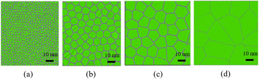
88 Jiarui Zhang et al.
grain rotation. Some authors showed that grain rotation et al. [36] investigated the synergistic effects of rolling
is much more evident in finer nanocrystals [11,12], while and annealing on the grain rotation and the resulted tex-
others reported a reversal size dependence of grain rota- ture in nickel.
tion [13]. Theoretical models were also established to Most of the existing researches relating to grain rota-
calculate the grain rotation rate considering the mass tion were carried out for the conventional metals with
diffusion and GB sliding, e.g., the efforts by Kim et al. uniform grain size distribution. It is widely known that
[14,15], Harris et al. [16], and Wheeler [17]. the conventional metals have long faced a dilemma of the
Grain rotation is usually accompanied with other strength-ductility tradeoff, i.e., an increase in strength
mechanical or thermal processes such as cracking, anneal- leading to a decrease in ductility and vice versa [1,37,38].
ing, and grain growth. Cracking is a special mechanical Recently, a novel approach for overcoming this dilemma
scenario in which the grain rotation mechanism may take was proposed by Lu [39] and other researchers [40,41]
effect. It has been found that the deformation at the crack who introduced gradient into the grain size distribution,
tip is accommodated by grain rotation in nanocrystalline referred to as gradient nano-grained (GNG) metals. The
metals. A number of in situ experiments [18] and theore- GNG metals have nonuniformly distributed grain size that
tical modeling efforts [19,20] have been devoted to inves- increases gradually from a few nanometers near the sur-
tigate the effect of grain rotation on the crack growth and face to several micrometers in the interior. They possess
blunting. For example, some authors (Li et al. [21,22], several exceptional properties such as high strength,
Zhang and Zhou [23]) showed that the nanograin rotation good strain hardening ability, satisfactory ductility, and
can significantly enhance the dislocation emission from excellent erosion resistance and can be economically
the crack tip, leading to evident crack blunting in nano- produced through mechanical surface treatments such
materials. Liu et al. [19] demonstrated that grain rotation- as mechanical surface attrition, frictional sliding, and
induced deformation mechanism can lead to an increase high energy shot peening [42–44]. These advantages
of the critical crack intensity factor. Grain rotation is also endow the GNG metals with a broad application potential
involved in the process of grain growth. The synergies and have attracted sustained research interests in inves-
among the grain rotation, the GB migration, the disloca- tigating the underlined mechanisms behind their intri-
tion activities, and the grain growth have also been guing mechanical behaviors [45,46].
explored in a number of researches through the theore- As reviewed by Chen et al. [47], grain rotation has
tical approach [20,24,25], the in situ TEM testing [26,27], been extensively studied through theoretical models,
the phase field simulations [28,29], etc. Several inter- molecular dynamics simulations, and experimental
esting phenomena and mechanisms have been reported. investigations. However, few efforts have been devoted
For example, Liu et al. [30] demonstrated that the coop- to grain rotation in the GNG metals. In our previous work
eration between the nano-grain rotation and the GB [48], the grain rotation behavior during the uniaxial ten-
migration could lead to the enhancement of the dislo- sion of nanocrystalline copper was investigated using the
cation emission. Moldovan et al. [31,32] demonstrated crystal plasticity finite element method (CPFEM). It was
that the grain coalescence induced by grain rotation found that the grain rotation rate does not show any
leads to the power-law rate of grain growth with a uni- dependence on grain size. Noting that the CPFEM frame-
versal scaling exponent. Farkas et al. [33] reported a work is based on the dislocation slip systems and does
linear kinetics for grain growth accompanied by grain not incorporate the GB mechanisms, the CPFEM results
rotation in the nanocrystalline Ni, which is different may deviate from the reality. On the other hand, ato-
from the square root kinetics observed in the coarse- mistic-based method such as molecular dynamics (MD)
grained counterparts. Vuppuluri and Vedantam [34] is a capable tool that can capture various mechanisms in
deduced the average grain growth rate as R ∼ t1/3 under the microstructure evolution of nanocrystalline metals
the coupled mechanisms of GB migration and grain rota- [49–51]. In this paper, we carried out a thorough MD study
tion coalescence. Besides cracking and grain growth, to investigate the grain rotation behavior in gradient nano-
grain rotation can also be mediated by other mechanical crystalline copper, which is a widely investigated material
or thermal processes. For example, Danilenko et al. [35] in the literature [52–54]. This work is aimed at promoting
observed annealing-induced grain rotation in ultrafine- the understanding of the synergistic deformation mechan-
grained aluminum alloy from in situ TEM studies. Wang isms of the nonuniform nano-grained materials.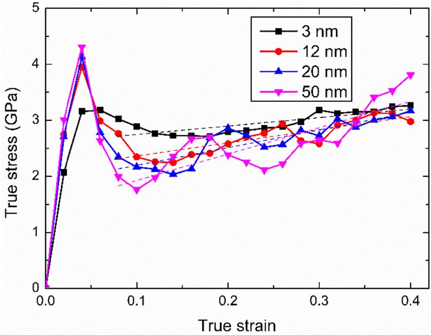
Deformation-induced grain rotations in gradient nano-grained copper 89
2 Molecular dynamics modelling of program was developed to fill in the atoms. In this work,
all the grains were orientated with their [111] crystal
GNG copper under uniaxial direction along the out-of-plane direction. The purpose
deformation of choosing the [111] orientation is that in that orienta-
tion, the three slip systems that could be possibly acti-
In real practice, the grain size of the GNG metals usually vated are (111)[110], (111)[011], and (111)[101], whose slip
changes from several nanometers on the surface to hun- directions are all within the plane (111) which is also
dreds of nanometers at a depth of 100 μm. Considering the specimen plane. The resulted grain rotation due the
the forbidden computational cost in MD that a cube of activation of these slip systems is always around the [111]
just 1 μm size contains 80 billion atoms, it is not feasible axis, causing the [111] crystal direction kept along the
to simulate a real GNG sample whose length is around out-of-plane direction. In this way, the rotation angle
100 μm. Therefore, we adopted an economic scheme to can be easily determined from the relative positions
save the computation cost by accelerating the gradient of atoms on the close-packed (111) plane. The initial
so that the grain size changes from several nanometers orientation of the grains followed a uniform random dis-
to tens of nanometers across a length of less than one tribution, resulting in GBs with randomly distributed mis-
micrometer. Besides, the sample possesses a quasi-three- orientation angles. The dimension of the MD sample is
dimensional configuration in which the thickness along about 1,000 × 2,000 × 18.75 Å3. In this work, the gradient
the out-of-plane direction is very small and the shape of of the model is represented by the combination of the
grains is actually columnar instead of equiaxed with the minimum grain size and the maximum grain size, e.g.,
axes along the out-of-plane direction. Figure 1(a) shows 3–25 representing the smallest grain size of 3 nm and the
one of the computational samples of GNG copper. The largest of 25 nm. Three MD samples with gradients of
computational samples were created using the home- 3–50, 3–25, and 3–10 were created. The smallest grain
made codes. Firstly, a MATLAB program was developed size was 3 nm and the largest grain size was 50 nm. The
to generate the gradient polycrystal topology using the reason for choosing this grain size range is that the smal-
Voronoi method. To incorporate the gradience in the lest grain size of 3 nm is believed to be the lower bound
grain size, the positions of the grain center seeds were for nanocrystalline metals and the largest grain size of
adjusted according to a linear varied distribution along 50 nm corresponds to the most computational cost that
the depth direction. After the generation of the GNG we can afford.
topology, the polycrystals were filled with copper atoms The simulations of uniaxial tensile deformation were
arranged in face-centered cubic (FCC) lattices whose carried out using the open source code LAMMPS. The
orientations vary from one grain to another. A FORTRAN embedded atom potential (EAM) was used to model the
interaction between atoms. The period boundary condi-
tion was applied to all the sample boundaries except for
the boundaries along the gradient direction. The dynamic
equations were explicitly integrated using the velocity
Verlet algorithm with a time step of 1 fs. The pressure
along the out-of-plane direction was kept at 1 atm using
the isothermal-isobaric (NPT) ensemble, while the pres-
sure along the gradient direction was left uncontrolled at
self-equilibrated state. Before loading application, the
samples were relaxed at the temperature of 300 K for
about 0.5 ns to iron out any possible energy-unfavorable
defects. Then a uniaxial affine deformation was applied
to the direction perpendicular to the grain size gradient
at a constant strain rate of 0.5 × 10⁹ s−1 with the tempera-
ture controlled at 300 K. This strain rate was chosen as a
result of the balance of the computational cost and the
computation fidelity. As a common limitation, molecular
Figure 1: Topological configuration of GNG copper with dynamic simulations suffer from the tiny integration
gradient 3–25. time step and the resulting extremely high strain rate.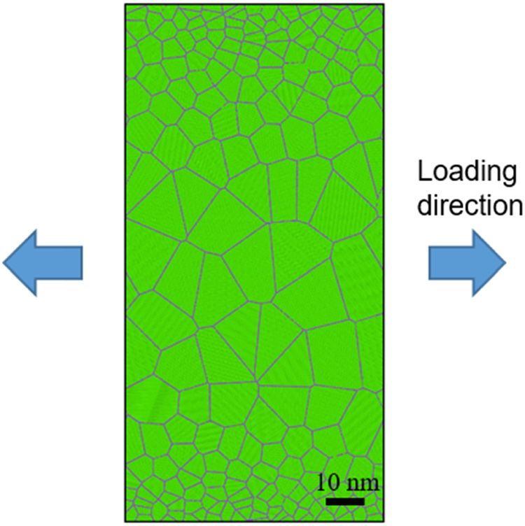
90 Jiarui Zhang et al.
Decreasing the strain rate would lead to a significant
increase of the computational cost. A case simulation
for the 50 nm grain-sized sample straining to 0.4 under
the rate of 0.5 × 10⁹ s−1 took 43.88 h using 256 nodes of
Shanghai Supercomputer Center clusters (Intel Skylake
Xeon, 2.6 GHz), which was close to the limit of computa-
tional cost we can afford. Although the adopted strain
rate is still several orders of magnitude higher than the
experimental strain rate of usually within 10−3 to 102, the
simulations are believed to be able to reflect the disloca-
tion-dominated grain rotation mechanisms. Besides, this
strain rate was also adopted in the literature [10]. The
maximum strain is unanimously set as 0.4 for all the
samples so that adequate significant plastic deformation
could take place.
To investigate the effect of grain size on the deforma- Figure 3: Stress versus strain curves for the MD samples with
tion behavior of the nanocrystalline copper, a series of different grain sizes, with the dashed lines being the linear fitting
for the strain range 0.08–0.4.
uniform grained samples with different grain sizes were
created (see Figure 2) and deformed under the same
and thus has a smaller modulus compared with the grain
loading conditions. The results of the uniform grained
interior region. Therefore, a smaller grain size corre-
samples were compared with those of the GNG sample to
sponds to a smaller Young’s modulus. From Figure 3,
provide insights into the synergistic deformation mechan-
the sample with smaller grain size also has a lower
isms in GNG metals.
peak stress, while the tendency is opposite in terms of
the plateau flow stress which is larger for the smaller
grain size. In general, the stress–strain curve is less
undulant for the smaller grain size. On the other hand,
3 Results the strain hardening effect is more obvious for the larger
grain size as can be seen by the steeper slope of the fitted
3.1 Stress versus strain curves lines of the plastic section of the stress–strain curve (see
the dash lines fitted for the strain range 0.08–0.4). This
Figure 3 compares the stress versus strain curves for the stronger strain hardening can be attributed to the more
uniform grained samples with different grain sizes. It evident dislocation activity in the larger grain size, as
shows that the Young’s modulus is smaller for the smaller shown later in Section 3.2. The material parameters obtained
grain size of 3 nm. This can be attributed to the larger from the stress–strain curves are listed in Table 1. The strain
fraction of GB region for the 3 nm sample. As reported hardening modulus of the 50 nm grain size is three times as
by the literature [55,56], the GB region is much less dense large as that of the 3 nm grain size.
Figure 2: MD samples of the nanocrystalline copper with grain size of (a) 3 nm, (b) 12 nm, (c) 20 nm, and (d) 50 nm.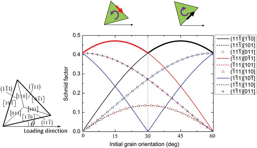
Deformation-induced grain rotations in gradient nano-grained copper 91
Table 1: Material parameters from the stress–strain curves for between the small grain (3 nm) sample and the large
different grain sizes grain (50 nm) sample in terms of the dislocation-GB
synergy and the grain coalescence/partition. In the small
Grain Young’s Yield Strain R2 of grain (3 nm) sample, the dislocations are relatively non-
size modulus stress hardening curve
uniformly distributed, i.e., the dislocations are abundant
(nm) (GPa) (GPa) modulus (GPa) fitting
in some grains, while scarce in others. On the other hand,
3 103.4 3.16 1.51 0.78 abundant dislocation activities can be seen in nearly all
12 137.4 3.95 2.35 0.80
the grains in the large grain (50 nm) sample. In the small
20 135.6 4.13 3.16 0.88
50 150.3 4.31 4.70 0.83
grain sample, the complete extended dislocations are
seldom displayed. The dislocations displayed are usually
leading partials (see solid arrows) which are nucleated
from the GBs, slip across the whole grains, and disappear
3.2 Dislocation activities in the opposite GBs. On the other hand, the complete
extended dislocations (see hollow arrows) can be clearly
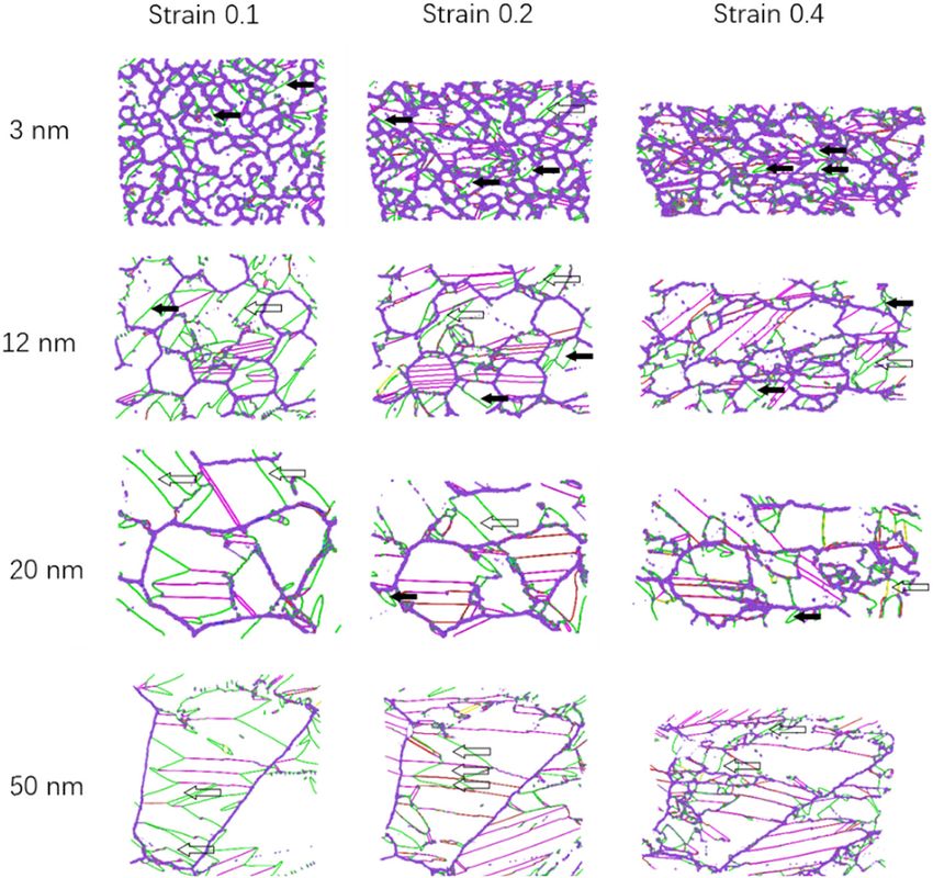
Figure 4 shows the snapshots of the samples during the seen in the large grains, with the leading partials, the
uniaxial deformation at strains 0.1, 0.2, and 0.4. In these trailing partials, and the stacking faults in between. In
graphs, the green lines indicate the Shockley partial dis- addition, dislocations in the large grains can also be
locations, the red lines indicate the stair-rod dislocations, nucleated from the grain interior besides the GBs. These
the atoms-colored blue are at the GBs, and all other phenomena indicate that the impediment effects of the
atoms are not displayed for clarity. To make the disloca- GBs on the dislocation activities are more evident in the
tion lines more clearly seen, only part of the samples are small grain sample. Another interesting phenomenon is
shown. Evident dislocation activities can be seen from all that in the small grain sample the grain coalescence pro-
these snapshots. However, some differences still exist cess is evident, while in the large grain sample the grain
Figure 4: Snapshots of the MD samples with different grain sizes during the uniaxial straining.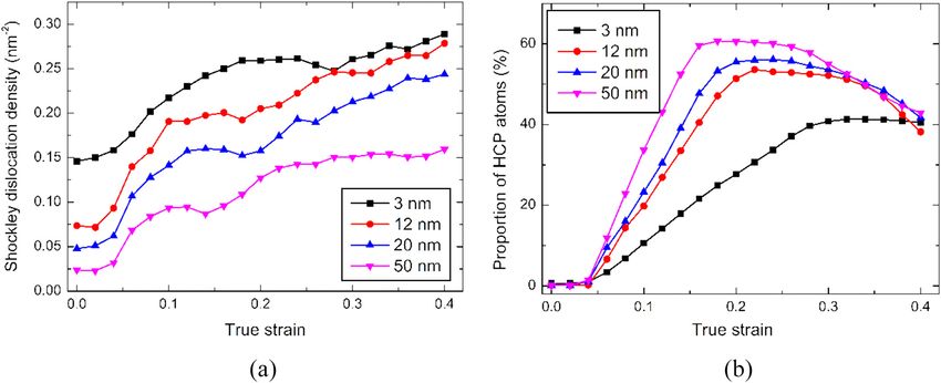
92 Jiarui Zhang et al.
Figure 5: Variations of (a) Shockley dislocation density and (b) the proportion of HCP atoms during the uniaxial deformation.
partition is the dominant process. This can be attributed metals using the CPFEM. It was found that the magnitude
to the abundant dislocation activities in the large grains of grain rotation strongly depends on the initial lattice
that the dislocations have large probability to intersect orientation of the grain, but does not depend on the
with each other, leading to the generation of sub-GB grain size. This conclusion may not hold true for real
structures. situations since the CPFEM framework only incorporates
The effect of the grain size on the dislocation activity the dislocation slip mechanisms and cannot reflect the GB
can be more clearly seen from the variations of Shockley mechanisms such as GB mass diffusion and GB sliding. In
dislocation density and the fraction of hexagonal close- this work, the phenomenon of grain rotation is investi-
packed (HCP) atoms during the deformation as shown in gated from our MD simulations. For this purpose, a pro-
Figure 5a and b, respectively. From Figure 5a, the density gram was developed to track the change of orientation for
of Shockley dislocation is larger for a smaller grain size. each grain based on the statistics on the relative positions
This can be explained by the larger fraction of GBs acting of all the atoms in that grain. The variation of the orienta-
as the dislocation sources in the small grain sample. tion angle with the strain is shown in Figure 6. Here, the
Nevertheless, the fraction of HCP atoms is less for the orientation angle is defined as the angle between the [11̄0]
sample with smaller grain size, as shown in Figure 5b. direction and the horizontal direction which is the tensile
Noting that HCP atoms are usually the atoms at the axis. Each curve in Figure 6 corresponds to one grain in
stacking faults, the proportion of HCP can be taken as a
measure of the intensity of dislocation activity. It indi-
cates that the larger grains are more favorable medium 60
for the motion of dislocations. From Figure 5b, it also
Grain orientation angle (deg)
50
shows that the HCP proportion reaches a saturated value
at a certain strain and will decrease as the strain further 40
increases. This decrease of HCP proportion can be attrib-
30
uted to the absorption of Shockley partial dislocations by
the GBs when the extended dislocations slide across the 20
whole grain. 10
0
0 0.1 0.2 0.3 0.4
True strain
3.3 Grain rotations
Figure 6: Variation of the orientation angle of each grain with the
In our previous work, the phenomenon of grain rotations strain, with different colors assigned just to differentiate the curves
was observed in the deformation simulations of GNG of different grains.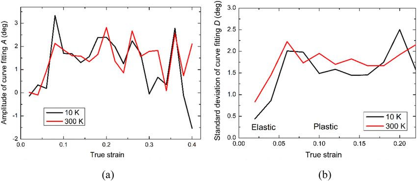
Deformation-induced grain rotations in gradient nano-grained copper 93
Table 2: cos λ of the involved slip directions activated once the resolved shear stress on it, measured
by the Schmid factor, exceeds that on other slip systems.
Slip plane cos λ As the plastic deformation goes on, the grain tends to
[011] cos(π /3 − θ) rotate to the orientation that the slip direction of the
[101] cos(π /3 + θ) activated slip system is parallel to the tensile axis. The
[110] cos θ Schmid factor μ is calculated as in equation (1)
[101] cos(π /6 − θ)/ 3 μ = ∣cos λ cos ϕ∣ (1)
[110] 1
3
sin θ
where, λ is the angle between the slip direction and the
[011] cos(π /6 + θ)/ 3
tensile axis, and ϕ is the angle between the normal of
slip plane and the tensile axis. For the configuration
Table 3: cos ϕ of the involved slip planes adopted in this work that the [111] crystal direction is
always along the out-of-plane direction, the possible
Slip direction cos ϕ slip systems that can be activated are the 9 slip systems,
i.e., (111)[011], (111)[101], (111)[110] on the slip plane (111),
(111) 2 2 cos(π / 6 + θ)/ 3
(111)[101], (111)[110], (111)[011] on the slip plane (111), and
(111) 2 2 cos(π / 6 − θ)/3
(111)[110], (111)[101], (111)[011] on the slip plane (111). Tables
(111) 2 2 sin θ /3
2 and 3 list the detailed expressions of the cos λ and cos ϕ
of equation (1) for the involved slip directions and slip
the sample. The orientation angle is wrapped to the range planes, respectively. From Tables 2 and 3, the Schmid
between 0 and 60o since the (111) crystal plane is triple factor μ for any of the 9 slip systems can be easily
symmetric. The breakings on the curves are caused by the obtained. For example, from Tables 2 and 3 and equa-
annihilation of that grain due to its coalescence with tion (1), μ = 2 2 ∣sin θ cos θ∣ / 3 = 2 ∣ sin 2θ∣ / 3 for the
other grains, or the generation of a new grain due to slip system (111)[110]. The variations of the Schmid factor
the dislocation activities. Figure 6 clearly shows that the with the initial grain orientation for different slip systems
orientation angle tends to converge to 30°, indicating the are shown in Figure 7. As can be seen, the Schmid factor
occurrence of texture. is highly dependent on the initial grain orientation.
This phenomenon is consistent with the theoretical When the initial grain orientation is between 0° and
model of the grain rotation under the uniaxial deforma- 30°, the slip system (111)[011] has the largest Schmid
tion due to the activation of different slip systems, as factor among all slip systems and thus will be activated,
demonstrated by Hosford [57]. The slip system will be leading to the anti-clockwise grain rotation. While for the
Figure 7: Dependence of the Schmid factor on the initial grain orientation for the 9 slip systems that have nonzero Schmid factor values.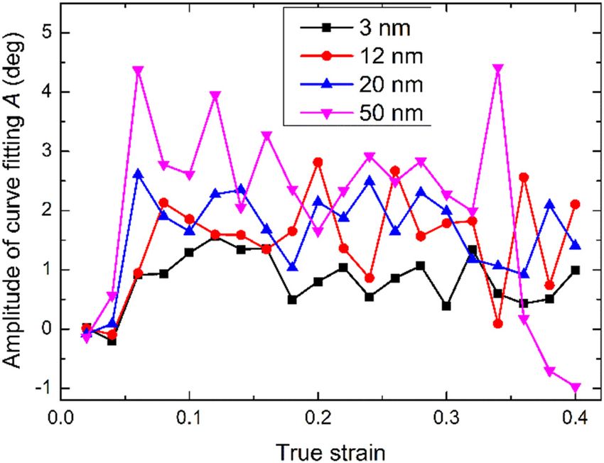
94 Jiarui Zhang et al.
initial grain orientation between 30° and 60°, the slip
system (111) [110] has the largest Schmid factor and is
the activated system, leading to the clockwise grain rota-
tion. From Figure 7, the Schmid factor takes its peak
values at the orientations 15° and 45°, respectively, for
the slip systems (111)[011] and (111)[110], indicating the
largest driving forces of the anti-clockwise and clockwise
grain rotation at these two orientations. It also indicates
that the rotation driving force becomes nullified at the
orientations 30°, 0°, and/or 60° because of the simulta-
neous activation of two of the three slip systems (111)[110],
(111)[011], and (111)[101] whose effects on the rotation are
opposite to each other at these orientations. Indeed, from
our MD simulations the grain rotation rate is positive in
the orientation range (0–30°) with its maximum at 15°,
while is negative in the orientation range (30–60°) with Figure 9: Variation of the amplitude of grain rotation increment with
the strain.
its minimum at 45°, as shown in Figure 8, which is from
the 20 nm sample at strain 0.2. Here, statistics on the
grain orientation are made at every 0.02 strain increment, The amplitude of the fitted curve A represents the
and the grain rotation rate is measured as the change of rate of the grain rotation, while the standard deviation
grain orientation during each strain increment. The var- of the fitting D represents the diversity of the grain rota-
iation tendency in Figure 8 shows an example of the tion distribution. For the specific sample shown in Figure 8,
dependence of grain rotation rate on the initial grain A and D are 2.16° and 1.35°, respectively. Figure 9 shows
orientation, which is representative for all the investi- the fitted amplitude varying with the strain. It shows that
gated samples. The resultant effect of the grain rotation larger grains rotate faster compared with the smaller
is that all grains tend to the orientation of 30°. grains, owing to the more evident dislocation activities
The results of the grain rotation Δθ versus the initial in the larger grains. This can lead to faster convergence of
grain orientation θ0 can be fitted by a sinusoidal function the grain orientation of larger grains. Indeed, if we plot
as equation (2). the standard deviation of the grain orientation from its
Δθ = A sin 6θ0 (2) stable value 30° versus the strain in Figure 10, the slope of
the curve is larger for the larger grain.
Figure 8: Dependence of grain rotation on the initial grain orienta-
tion, with the dots for the rotation results of each grain, and the Figure 10: Variation of the deviation of the grain orientation from 30°
curve for the data fitting. versus the strain.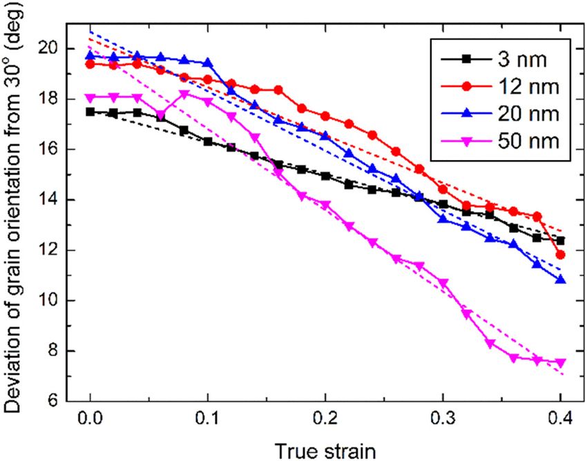
Deformation-induced grain rotations in gradient nano-grained copper 95
Table 4: Grain rotation results for different grain sizes
Grain size (nm) A (deg) D (deg) k (deg)
3 0.92 2.28 13.39
12 0.95 2.23 18.97
20 2.61 1.96 24.30
50 4.37 1.65 31.08
size range is from 3 to 50 nm. Within that range, the results
show a monotonic increase of grain rotation amplitude
and a monotonic decrease of the dispersion of the grain
rotation distribution as the grain size increases. Whether
these trends are suitable for grain sizes outside of this
range is remained for future study.
Figure 11: Variation of the standard deviation of grain rotation
increment with the strain.
3.4 Effect of temperature
On the other hand, Figure 11 shows that the standard We further investigated the effect of temperature on the
deviation of the grain rotation rate is larger for the stress–strain curve and the grain rotation behavior. For
smaller grains, especially for the elastic deformation this purpose, additional simulations were carried out for
range, indicating the larger diversity of the grain rotation straining the sample of 12 nm grain size at the tempera-
distribution for the smaller grains. This phenomenon ture of 10 K. The stress–strain curve is shown in Figure 12.
may be attributed to the effects of GB mechanisms such It is seen that the yield stress and the plateau stress
as the GB sliding and the GB diffusion on the grain rota- at 10 K temperature are higher than those at 300 K tem-
tion. As the grain size decreases, the GB mechanisms play perature, indicating a harder mechanical response at
a more important role, leading to the larger proportion of a lower temperature. Similar to the grain rotation beha-
the GB-induced grain rotation driven by the GB energy vior at 300 K, the dependence of grain rotation on
and the external work [2]. As demonstrated in the litera- the initial grain orientation at 10 K can also be fitted
ture [2], the GB-induced grain rotation mechanism is not by a sinusoidal curve. The fitting results are shown in
a cause of texture, but can be taken as a disturbance to Figure 13. Figure 13(a) shows that the fitted amplitude
the sinusoidal type grain rotation distribution shown in is not sensitive to the temperature, while Figure 13(b)
Figure 8. It is noted from Figure 11 that as the strain shows that the standard deviation of the fitting is larger
reaches the plastic stage, the dependence of the standard
deviation of grain rotation on the grain size becomes
opaque, which is different from the elastic stage. This
could be attributed to the dominance of the dislocation
slip-induced grain rotation mechanism which favors the
large grains in the plastic stage. After reaching the plastic
stage, the abundant dislocation activities give rise to the
significant slip-induced grain rotation, whose fluctuation
surpasses the contribution of the GB-induced grain rota-
tion. Therefore, the smaller grains can no longer exhibit a
larger fluctuation of grain rotation than the larger grains.
As a summary of the effects of grain size on the grain
rotation, Table 4 lists the amplitude A and the standard
deviation D for fitting the grain rotation distribution at
0.06 strain, as well as the slope k of the grain orientation
deviation from 30° versus the strain (see Figure 10) for
different grain sizes. It is noted that the investigated grain Figure 12: Temperature effect on the stress–strain curve.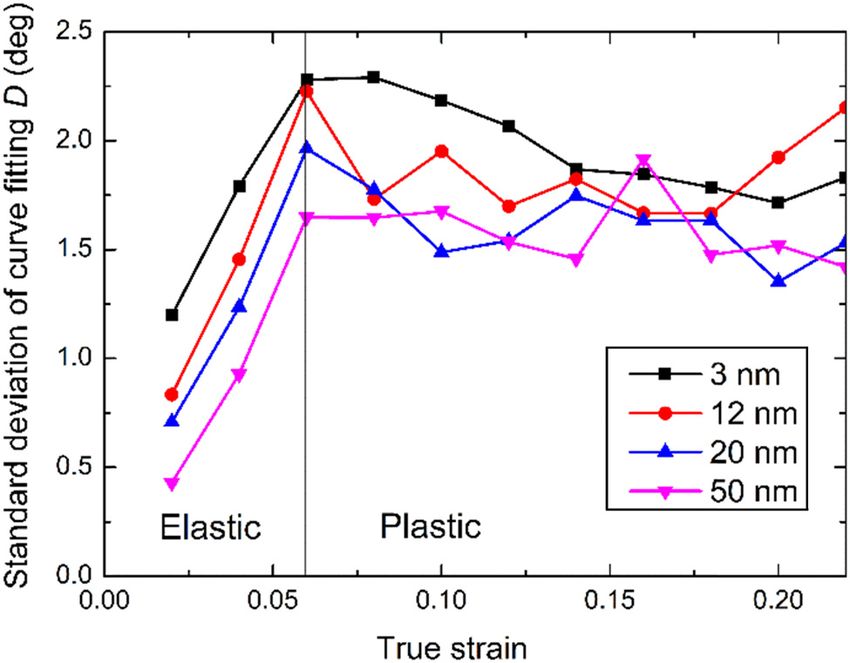
96 Jiarui Zhang et al.
Figure 13: Temperature effect on (a) the amplitude and (b) the standard deviation of the curve fitting for the initial orientation dependence of
grain rotation rate.
at 300 K than that at 10 K. This can be possibly attributed (3) Grain rotation was observed and its rate was found to
to the stronger contribution of GB-induced grain rotation depend on the initial crystal orientation. It makes the
at the increased temperature, leading to a larger disper- orientations of all grains tend to 30°, leading to the
sion in the grain rotation distribution at 300 K compared texture during the uniaxial tensile deformation.
to that at 10 K. On the other hand, the magnitude of grain (4) The grain rotation magnitude is larger for larger
rotation induced by the dislocation slip is not much sen- grains, but the rotation rate is more diversely distri-
sitive to the temperature change. buted for smaller grains, indicating more disturbance
from the GB mechanisms such as the GB sliding and
the GB diffusion for smaller grains.
(5) The grain rotation magnitude at 10 K temperature
4 Conclusions and discussions is comparable to that at 300 K, while the rota-
tion rate is less diversely distributed at the lower
In this paper, grain rotations induced by the deformation temperature.
in the GNG copper was explored using MD simulations. Although we did not investigate other nanocrystal-
First, the computational samples of GNG copper were created line metals, we believe that some of the conclusions
using Voronoi method. A systematic study was carried out to obtained from the simulations of copper in this paper
investigate the stress–strain curves, the dislocation activities, are applicable to other FCC metals. For example, domi-
and the grain rotation through simulations of different grain- nated by the dislocation slip mechanism, the grain
sized samples. The synergistic effects of the dislocation rotation magnitude is larger for larger grains, while the
mechanisms and the grain boundary mechanisms on the rotation rate is more diversely distributed for smaller
grain rotation were evaluated. The following conclusions grains due to the influence of the GB mechanisms.
can be drawn. However, whether these conclusions are applicable for
(1) Among the investigated grain size from 3 to 50 nm, other types of metals are difficult to be judged. Besides,
the 3 nm grain size corresponds to the smallest the current study is based on the conventional nano-
Young’s modulus, but the largest plateau flow stress. crystalline metals, and the conclusions may not be sui-
On the other side, the 50 nm grain size corresponds to table for nano-twinned crystals. The complex interactions
the strongest strain hardening capability. between the twin boundaries and the dislocations [58,59]
(2) The larger grains are more favorable for the motion of will possibly make the grain rotation behavior different from
dislocations, leading to larger fraction of HCP atoms that without twin boundaries. These topics are remained for
during the deformation. future study.Deformation-induced grain rotations in gradient nano-grained copper 97
Author contributions: All authors have accepted respon- [15] Kim B-N, Hiraga K, Morita K, Yoshida H, Ahn B-W. Viscous
sibility for the entire content of this manuscript and grain-boundary sliding with rotating particles or grains. Acta
approved its submission. Mater. 2009;57(19):5730–8.
[16] Harris KE, Singh VV, King AH. Grain rotation in thin films of
gold. Acta mater. 1998;46(8):2623–33.
Research funding: The authors acknowledge the sup- [17] Wheeler J. Anisotropic rheology during grain boundary diffu-
port from National Natural Science Foundation of China sion creep and its relation to grain rotation, grain boundary
(11772231), Shanghai Science and Technology Innovation sliding and superplasticity. Philos Mag. 2010;90(21):2841–64.
Plan (20ZR1462700), and Shanghai Supercomputer Center. [18] Vetterick G, Leff AC, Marshall M, Baldwin JK, Misra A, Hattar K,
et al. Direct observation of a coincident dislocation- and grain
boundary-mediated deformation in nanocrystalline iron. Mater
Conflict of interest: The authors state no conflict of Sci Eng A. 2018;709:339–48.
interest. [19] Liu Y, Zhou J, Shen TD, Hui D. Grain rotation dependent fracture
toughness of nanocrystalline materials. Mater Sci Eng A.
2011;528(25–26):7684–7.
[20] Ovid’Ko IA, Sheinerman AG. Nanoscale rotational deformation
near crack tips in nanocrystalline solids. J Phys D: Appl Phys.
References 2012;45(33):335301.
[21] Li J, Chen S, Weng GJ. Significantly enhanced crack blunting by
[1] Meyers MA, Mishra A, Benson DJ. Mechanical properties of nanograin rotation in nanocrystalline materials. Scr Mater.
nanocrystalline materials. Prog Mater Sci. 2018;151:19–23.
2006;51(4):427–556. [22] Li J, Chen S, Weng GJ, Liu C. Stress-assisted grain-rotation-
[2] Yang F, Yang W. Kinetics and size effect of grain rotations in induced dislocation emission from grain boundaries in nano-
nanocrystals with rounded triple junctions. Scr Mater. crystalline face-centered-cubic metals. Philos Mag Lett.
2009;61(9):919–22. 2019;99(12):466–78.
[3] Chandel VS, Wang G, Talha M. Advances in modelling and [23] Zhang F, Zhou J. Grain sizes effect on crack blunting consid-
analysis of nano structures: a review. Nanotech Rev. ering nano-grain rotation and dislocation-GB interactions.
2020;9(1):230–58. Mech Mater. 2019;129:214–21.
[4] Wang L, Teng J, Liu P, Hirata A, Ma E, Zhang Z, et al. Grain [24] Li J, Soh AK, Wu X. On nanograin rotation by dislocation climb
rotation mediated by grain boundary dislocations in nano- in nanocrystalline materials. Scr Mater. 2014;78–79:5–8.
crystalline platinum. Nat Commun. 2014;5:4402. [25] Li J, Qin F, Lu W, Weng GJ. A synergetic grain growth
[5] Li X, Zhou J, Zhu R, Liu Y, Jiang H. Grain rotation dependent mechanism uniting nanograin rotation and grain boundary
non-homogeneous deformation behavior in nanocrystalline migration in nanocrystalline materials. Results Phys.
materials. Mater Sci Eng A. 2010;527(21–22):5677–85. 2019;14:102381.
[6] Shu X, Kong D, Lu Y, Long H, Sun S, Sha X, et al. Size effect on [26] Mompiou F, Legros M. Quantitative grain growth and rotation
the deformation mechanisms of nanocrystalline platinum thin probed by in situ TEM straining and orientation mapping in
films. Sci Rep. 2017;7:13264. small grained Al thin films. Scr Mater. 2015;99:5–8.
[7] Yang F, Yang W. Crack growth versus blunting in nanocrystal- [27] Ossai CI, Raghavan N. Nanostructure and nanomaterial char-
line metals with extremely small grain size. J Mech Phys acterization, growth mechanisms, and applications. Nanotech
Solids. 2009;57(2):305–24. Rev. 2018;7(2):209–31.
[8] Ni H, Wang L, Wang Z, Zhu J. Grain orientation induced soft- [28] Vuppuluri A. Theory and simulation of microstructure evolution
ening in electrodeposited gradient nanostructured nickel due to simultaneous grain boundary migration and grain
during cold rolling deformation. Rev Adv Mater Sci. rotation with misorientation dependent energy and mobility.
2020;59:144–50. Mater Sci Eng A. 2018;713:118–24.
[9] Wu Q, Miao W, Zhang Y, Gao H, Hui D. Mechanical properties of [29] Trautt ZT, Mishin Y. Capillary-driven grain boundary motion
nanomaterials: a review. Nanotech Rev. 2020;9:259–73. and grain rotation in a tricrystal: A molecular dynamics study.
[10] Ruestes CJ, Bertolino G, Ruda M, Farkas D, Bringa EM. Grain Acta Mater. 2014;65:19–31.
size effects in the deformation of [0001] textured nanocrys- [30] Liu C, Lu W, Weng GJ, Li J. A cooperative nano-grain rotation
talline Zr. Scr Mater. 2014;71:9–12. and grain-boundary migration mechanism for enhanced dis-
[11] Zhou X, Tamura N, Mi Z, Zhang L, Ke F, Chen B. Measuring grain location emission and tensile ductility in nanocrystalline
rotation at the nanoscale. High Pressure Res. materials. Mater Sci Eng A. 2019;756:284–90.
2017;37(3):287–95. [31] Moldovan D, Yamakov V, Wolf D, Phillpot SR. Scaling behavior
[12] Chen B, Lutker K, Lei J, Yan J, Yang S, Mao H-K. Detecting grain of grain-rotation-induced grain growth. Phys Rev Lett.
rotation at the nanoscale. PNAS. 2014;111(9):3350–3. 2002;89(20):206101.
[13] Zhou X, Tamura N, Mi Z, Lei J, Yan J, Zhang L, et al. Reversal in [32] Moldovan D, Wolf D, Phillpot SR. Theory of diffusion-accom-
the size dependence of grain rotation. Phys Rev Lett. modated grain rotation in columnar polycrystalline micro-
2017;118(9):096101. structures. Acta Mater. 2001;49(17):3521–32.
[14] Kim B-N, Hiraga K, Morita K. Viscous grain-boundary sliding [33] Farkas D, Mohanty S, Monk J. Linear grain growth kinetics and
and grain rotation accommodated by grain-boundary diffu- rotation in nanocrystalline Ni. Phys Rev Lett.
sion. Acta Mater. 2005;53(6):1791–8. 2007;98(16):165502.98 Jiarui Zhang et al.
[34] Vuppuluri A, Vedantam S. Grain growth rate for coupled grain [47] Chen B, Zhu L, Xin Y, Lei J. Grain rotation in plastic deforma-
boundary migration and grain rotation in nanocrystalline tion. Quantum Beam Sci. 2019;3(3):17.
materials. Philos Mag Lett. 2016;96(9):339–46. [48] Li Z, Yang F. Grain rotations during uniaxial deformation of
[35] Danilenko VN, Bachurin DV, Nazarov AA. Annealing-induced gradient nano-grained metals using crystal plasticity finite
grain rotation in ultrafine-grained aluminum allay. Rev Adv element simulations. Extreme Mech Lett. 2017;16:41–8.
Mater Sci. 2018;55(1):69–77. [49] Cao P. The strongest size in gradient nanograined metals.
[36] Wang L, Chen X, Luo T, Ni H, Mei L, Ren P, et al. Effect of cross Nano Lett. 2020;20(2):1440–6.
cold rolling and annealing on microstructure and texture in [50] Li X, Wei Y, Lu L, Lu K, Gao H. Dislocation nucleation governed
pure nickel. Rev Adv Mater Sci. 2020;59:252–63. softening and maximum strength in nano-twinned metals.
[37] Ritchie RobertO. The conflicts between strength and tough- Nature. 2010;464(7290):877–80.
ness. Nat Mater. 2011;10(11):817–22. [51] Zhou H, Qu S, Yang W. An atomistic investigation of structural
[38] Wei Y, Li Y, Zhu L, Liu Y, Lei X, Wang G, et al. Evading the evolution in metallic glass matrix composites. Int J Plast.
strength–ductility trade-off dilemma in steel through gradient 2013;44:147–60.
hierarchical nanotwins. Nat Commun. 2014;5:3580. [52] Guo X, Song K, Xu W, Li G, Zhang Z. Effect of TiB2 particle size
[39] Lu K. Making strong nanomaterials ductile with gradients. on the material transfer behaviour of Cu-TiB2 composites.
Science. 2014;345(6203):1455–6. Mater Sci Tech. 2020;26(5):1–10.
[40] Fang TH, Li WL, Tao NR, Lu K. Revealing extraordinary intrinsic [53] Long F, Guo X, Song K, Jia S, Yakubov V, Li S, et al. Synergistic
tensile plasticity in gradient nano-grained copper. Science. strengthening effect of carbon nanotubes (CNTs) and titanium
2011;331(6024):1587–90. diboride (TiB2) microparticles on mechanical properties of
[41] Fan J, Zhu L, Lu J, Fu T, Chen A. Theory of designing the gradient copper matrix composites. J Mater Res Tech.
microstructured metals for overcoming strength-ductility 2020;9(4):7989–8000.
trade-off. Scr Mater. 2020;184:41–5. [54] Feng J, Song K, Liang S, Guo X, Jiang Y. Electrical wear of TiB2
[42] Deng SQ, Godfrey A, Liu W, Zhang CL. Microstructural evolu- particle-reinforced Cu and Cu–Cr composites prepared by
tion of pure copper subjected to friction sliding deformation at vacuum arc melting. Vacuum. 2020;175:109295.
room temperature. Mater Sci Eng A. 2015;639:448–55. [55] Farkas D. Fracture resistance of nanocrystalline Ni. Metall
[43] Yang L, Tao NR, Lu K, Lu L. Enhanced fatigue resistance of Cu Mater Trans A. 2007;38:2168–73.
with a gradient nanograined surface layer. Scr Mater. [56] Giallonardoab JD, Erba U, Austa KT, Palumbo G. The influence
2013;68(10):801–4. of grain size and texture on the Young’s modulus of nano-
[44] Muhamad SS, Ghani JA, Haron CHC, Yazid H. Cryogenic milling crystalline nickel and nickel–iron alloys. Philos Mag.
and formation of nanostructured machined surface of AISI 2011;91:4594–605.
4340. Nanotech Rev. 2020;9:1104–17. [57] Hosford WF. Mechanical behavior of materials. Cambridge:
[45] Fan JT, Yan YM. Gradient microstructure with martensitic Cambridge University Press; 2005.
transformation for developing a large-size metallic alloy with [58] Qu S, Zhou H. Hardening by twin boundary during nanoin-
enhanced mechanical properties. Mater Des. 2018;143:20–6. dentation in nanocrystals. Nanotechnology. 2010;21:335704.
[46] Fan J, Jiang M. Strain hardenability of a gradient metallic alloy [59] Zhou H, Qu S. The effect of nanoscale twin boundaries on
under high-strain-rate compressive loading. Mater Des. fracture toughness in nanocrystalline Ni. Nanotechnology.
2019;170:107695. 2010;21:035706.You can also read