High-performance lasers for fully integrated silicon nitride photonics
←
→
Page content transcription
If your browser does not render page correctly, please read the page content below
High-performance lasers for fully integrated silicon nitride photonics

                                                                    Chao Xiang,1, ∗ Joel Guo,1 Warren Jin,1 Jonathan Peters,1 Weiqiang Xie,1 Lin
                                                                 Chang,1 Boqiang Shen,2 Heming Wang,2 Qi-Fan Yang,2 Lue Wu,2 David Kinghorn,1, 3
                                                                     Mario Paniccia,4 Kerry J. Vahala,2 Paul A. Morton,5 and John E. Bowers1, †
                                                                        1
                                                                         Department of Electrical and Computer Engineering, University of California,
                                                                                     Santa Barbara, Santa Barbara, California 93106, USA
                                                          2
                                                            T. J. Watson Laboratory of Applied Physics, California Institute of Technology, Pasadena, CA 91125, USA
                                                                             3
                                                                               Pro Precision Process and Reliability LLC, Carpinteria, CA, USA
                                                                                          4
                                                                                            Anello Photonics, Santa Clara, CA, USA
                                                                                  5
                                                                                    Morton Photonics,West Friendship, Maryland 21794, USA
arXiv:2104.08414v1 [physics.optics] 17 Apr 2021

                                                   Silicon nitride (SiN) waveguides with ultra-low               radio-frequency filtering21 and so on.
                                                  optical loss enable integrated photonic applica-                  SiN photonics has been largely restricted at the stand-
                                                  tions including low noise, narrow linewidth lasers,            alone component level as the integration with active de-
                                                  chip-scale nonlinear photonics, and microwave                  vices including lasers, modulators, amplifiers and pho-
                                                  photonics1 . Lasers are key components to SiN                  todetectors has been difficult. First of all, as a dielec-
                                                  photonic integrated circuits (PICs), but are diffi-            tric material, SiN lacks a direct energy bandgap for effi-
                                                  cult to fully integrate with low-index SiN waveg-              cient carrier radiative recombination or electro-optic ef-
                                                  uides due to their large mismatch with the high-               fect, which are the basis of lasers and modulators. In
                                                  index III-V gain materials. The recent demon-                  addition, the refractive index of SiNx at telecommunica-
                                                  stration of multilayer heterogeneous integration               tion wavelength (1.55 µm) is around 2, depending on the
                                                  provides a practical solution and enabled the first-           silicon content. This low refractive index possess sig-
                                                  generation of lasers fully integrated with SiN                 nificant difficulties in its integration with active III-V
                                                  waveguides2–4 . However a laser with high device               gain materials through direct heterogeneous III-V/SiN
                                                  yield and high output power at telecommunica-                  integration, analogous to heterogeneous III-V/Si integra-
                                                  tion wavelengths, where photonics applications                 tion, which has achieved success in optical interconnect
                                                  are clustered, is still missing, hindered by large             applications22,23 .
                                                  mode transition loss, nonoptimized cavity design,                 Recent progress in multilayer integration leverages an
                                                  and a complicated fabrication process. Here,                   intermediate Si layer as the index matching layer to cre-
                                                  we report high-performance lasers on SiN with                  ate III-V/Si/SiN structures2 . This structure not only
                                                  tens of milliwatts output through the SiN waveg-               provides optical gain to SiN photonic circuits so that
                                                  uide and sub-kHz fundamental linewidth, ad-                    lasers or amplifiers can be formed, but can also enrich the
                                                  dressing all of the aforementioned issues. We also             photonic functionalities of SiN photonic circuits as opti-
                                                  show Hertz-level linewidth lasers are achievable               cal modulation24 and detection25 are also enabled using
                                                  with the developed integration techniques. These               existing III-V/Si or Si devices. Another compelling op-
                                                  lasers, together with high-Q SiN resonators, mark              portunity through the integration of ultra-low-loss SiN
                                                  a milestone towards a fully-integrated low-noise               into various photonic device is that the device perfor-
                                                  silicon nitride photonics platform. This laser                 mance can be optimized with another degree of free-
                                                  should find potential applications in LIDAR, mi-               dom. One prominent example is the semiconductor laser
                                                  crowave photonics and coherent optical commu-                  linewidth, which is largely restricted to the MHz range
                                                  nications.                                                     for monolithic III-V lasers26 . The underlying prospect is
                                                     Silicon nitride photonics is emerging in recent years       that low-loss Si waveguides and ultra-low loss SiN waveg-
                                                  as advanced photonic devices require better performance        uides can offer orders-of-magnitude longer optical cavities
                                                  than is available from traditional Si or InGaAsP waveg-        compared to III-V or Si waveguides, to reduce the laser
                                                  uides. As a fully CMOS-compatible material, SiN-               linewidth due to the reduced optical loss. Sub-kHz and
                                                  based waveguides offer low optical propagation loss, wide      Hz-level fundamental linewidth semiconductor lasers are
                                                  transparency from the visible to the infrared, a low           demonstrated though heterogeneous or hybrid integra-
                                                  thermo-optic coefficient and absence of nonlinear ab-          tion of III-V gain with low-loss Si27–29 or SiN30–33 .
                                                  sorption loss5–8 , thus forming the backbone of chip-             High-power, low-noise semiconductor lasers are of crit-
                                                  scale nonlinear photonics9–12 , high-fidelity integrated mi-   ical importance in many applications including coherent
                                                  crowave photonics systems13 and ultra-broadband inte-          communications, LIDAR and remote sensing34 . Here
                                                  grated photonic circuits14,15 . As a result, SiN-based         we demonstrate high-power (>10 mW), low-noise (
2
a Si photonic circuits InP/Si Si/SiN SiN photonic circuits
P-contact P-InGaAs
heater
P-InP
N-contact H+ H+ In0.53Al0.183Ga0.287As QW
N-InP Si Upper SiO2
Spacer SiO2
4. Passivation
SiN
Buried SiO2 and metallization
Si substrate
SOI InP
1. SiN processing 2. Si processing 3. InP processing
b
SiN grating SiN laser output InP/Si gain
H+ implant
SiN P-InP
SiN post
P contact
SiN core Si
N contact
Si reflector N-InP Si
InP/Si
Phase tuner
Probe pad
Si loop mirror
Ti/Pt heater
Si MZI
Figure 1. Laser design and fabrication schematics. a. A cross-sectional schematic illustration of the fabricated InP/Si/SiN
laser integrated with Si photonic circuits and SiN photonic circuits after the laser passivation and before probe metal deposition
(top). Three insets on the bottom show the fabrication process including SiN processing and SOI bonding (left), Si processing
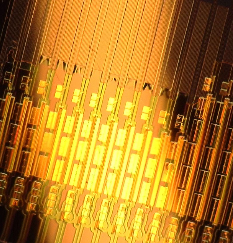
and InP bonding (middle), and InP processing (right). b. A device optical photograph showing InP/Si/SiN DBR laser arrays.
The lasers consist of four sections including the SiN grating, InP/Si gain section, Si reflector and phase tuner, with each
schematic shown respectively.
Hertz-level fundamental linewidth on-chip lasers, and cessing respectively. SOI bonding uses a large piece of
can also directly generate optical frequency combs. Our SOI (500-nm thick Si layer) to cover the entire device area
high-performance laser could be a key enabler for fully- including laser gain area and SiN photonic circuits, which
integrated SiN photonics featured with on-chip frequency helps to maintain the low loss of SiN waveguides during
comb generation capability35–37 , ultra-low phase noise III-V processing. As a result, in addition to standard
enabled by self-injection locking32 , high fidelity for mi- III-V processing as used in III-V/Si lasers, the removal
crowave photonics38–41 , high channel-count for DWDM of excess Si on top of the SiN photonic circuits except
(dense wavelength division multiplexing) systems42 and the taper needs to be performed before laser passivation.
so on. Equipped by this multilayer structure, our laser con-
Laser design. The laser is constructed in a way that tains the following main sections as shown in Fig. 1b:
the Si layer, sandwiched between the III-V epi layer and SiN Bragg grating, InP/Si gain, Si reflector and phase
SiN layer, bridges the refractive indices and provides ad- tuner. The SiN grating is a low-κ (coupling constant)
ditional intra-cavity phase control capability. As shown side post grating, made by placing SiN posts along the
in Fig. 1a, two wafer bonding steps, including SOI bond- SiN waveguide core on both sides. The gap width be-
ing and InP bonding, follow SiN processing and Si pro- tween the core and posts is constant and can be tailored3
a 25 b c
0
-1
2.5 mm, 0.25 cm
0
2.5 mm, 0.75 cm -1
SiN waveguide power (mW)
20
Normalized reflection (dB)
-1
1.5 mm, 0.875 cm
-5
-20
Power (dBm)
15
10
-40
-10
5
-60
0 -15
50 100 150 200 250 300 -0.1 -0.05 0 0.05 0.1 1520 1530 1540 1550 1560 1570
Current (mA) (nm) Wavelength (nm)
d e
-120
10 5 230mA
300mA
Frequency noise (Hz2 /Hz)
-130
RIN (dBc/Hz)
10 4 -140
-150
3
10
-160
10 2 3 -170
10 10 4 10 5 10 6 10 7 10 8 0 5 10 15 20
Offset frequency (Hz) RF frequency (GHz)
Figure 2. Laser characterization. a. LI measurements of three lasers with different gain section length (1.5 mm or 2.5 mm)
and grating κ values (0.25 cm-1 , 0.75 cm-1 and 0.875 cm-1 ). b. Corresponding grating reflection response of lasers measured
in a. c. Optical spectrum of high-power laser (shown in blue in a and b) at a gain current of 300 mA. d. Laser frequency
noise spectrum of a laser with sub-kHz fundamental linewidth and low frequency noise. e. Laser RIN measurements of a
low-threshold laser (shown in green in a and b).
to achieve the desired κ value. In order to achieve a long interferometer power splitting ratio and, consequently,
cavity length with high singlemode selectivity, the grat- the total reflectivity. The Si reflector is designed to pro-
ings use the maximum available 20 mm in length to fit the vide 100 % power reflectivity with zero bias as the initial
laser within a deep ultra-violet (DUV) stepper mask reti- state. A phase tuner using a thermally tuned heater is
cle, providing an extended-distributed Bragg reflector (E- included between the InP/Si gain and SiN grating, to
DBR). The InP/Si gain section uses a hybrid InP/Si ac- tune the cavity phase condition. The E-DBR laser out-
tive waveguide with mode transition tapers to the under- put is taken through the SiN grating in a SiN waveguide,
neath Si waveguide. Details of this type of hybrid section followed by a SiN inverse taper for efficient chip-to-fiber
can be found in previous work43 . The gain section lengths coupling and off-chip laser characterization. The laser
are chosen to be 2.5 mm or 1.5 mm in different laser de- output could also be directed to other SiN photonic in-
signs. Here the Si waveguide is shallow etched with 231 tegrated circuits and devices on demand.
nm etch depth to support single transverse-electric (TE)
In our E-DBR laser, the SiN waveguide is 90-nm thick
mode in the hybrid InP/Si waveguide section. After for-
and 2.8-µm wide, with an effective mode refractive index
mation of the wide InP mesa and laser passivation, pro-
around 1.46 and effective mode area of 5.3 µm2 . In order
ton implantation is implemented to define the electrical
to enable a highly efficient mode conversion between the
current channels for efficient carrier injection. While the
Si waveguide and SiN waveguide, the shallow-etched Si
SiN grating provides narrow-band feedback for one mir-
waveguide mode is transformed to 269-nm thick Si fully-
ror, the other mirror is a broadband Si reflector based
etch waveguide mode and then tapered to a 150-nm wide
on a tunable Si loop mirror. A thermally-controlled Si
taper tip over a 50-µm length. The laser fabrication is a
MZI (Mach–Zehnder interferometer) is used to tune the
wafer-scale process, which is performed on a 100-mm di-4 ameter wafer and all the optical lithography is performed strong grating κ value and 2.5-mm long gain section is using a DUV stepper. Details of the fabrication process shown in Fig. 2d. The Lorentzian linewidth is around can be found in Methods. 780 Hz, thanks to the large grating slope on the long Laser characterization. Figure 2 summarizes the wavelength side of the reflection response, which provides laser characterization results. The laser output power is a strong negative feedback to reduce the laser linewidth. measured from the output-coupled optical lensed fiber. We also measured the relative-intensity-noise (RIN) of The coupling loss is 3.5 dB from the SiN inverse taper at the 1.5 mm-long gain section laser (0.875 cm-1 grating the chip facet. The light-current (LI) curves are shown in κ). The results are shown in Fig. 2e. For gain currents Fig. 2a for three lasers with different gain section lengths around 230 mA and 300 mA, the RIN are measured be- (1.5 mm or 2.5 mm) and different SiN grating κ designs low -150 dBc/Hz up to 20 GHz. This low RIN is due to (0.25 cm-1 , 0.75 cm-1 and 0.875 cm-1 ). The SiN output the narrow bandwidth feedback from the SiN grating. waveguide power is above 10 mW for each of these lasers. Integration with ultra-high-Q SiN photonics. The LI measurements show that a longer gain section With the laser fully-integrated within SiN photonic inte- length together with a smaller grating κ value (weaker grated circuits, its performance can be further enhanced grating feedback) are advantageous for higher laser out- by the addition of ultra-low-loss and ultra-high-Q SiN put power, as a smaller κ corresponds to a larger mirror photonics devices. Moving towards an ultra low phase loss at the output facet. The minimum κ value, which noise system, our laser can be integrated with an ultra- represents the minimum grating feedback strength sus- high-Q SiN ring resonator. For a proof-of-concept, here taining lasing conditions, is determined with a combi- we butt coupled our SiN laser with a stand-alone SiN nation of factors including the laser gain, intrinsic loss, high-Q ring resonator with nominal intrinsic Q factor Si/SiN taper loss and SiN waveguide loss30 . The laser around 40 million. threshold also depends on the laser gain section length Figure 3a summarizes the influence of external cav- and the grating feedback. A short gain section length of ity feedback from the resonator on the laser coherence. 1.5 mm together with a large grating κ value of 0.875 Within the E-DBR laser, due to the large mode mismatch cm-1 results in the low laser threshold of 42 mA for the between the Si and SiN waveguides, efficient mode tran- long external cavity laser (20 mm-long external cavity). sition with low reflection is only possible when the taper The SiN grating reflection responses for the three lasers in tip is narrow. On the other hand, in devices where the Fig. 2a are shown in Fig. 2b. From the normalized reflec- taper tip is wider and provides enough feedback, the laser tion, it is clear that the smaller grating κ design results can lase from the wide taper tip and high-reflection re- in a narrower reflection bandwidth, however with limited flector in a Fabry-Pérot (FP) mode (in mode competition side lobe suppression (3.5 dB). For larger κ values, the with SiN grating based lasing), with the output coupled grating reflection bandwidth would increase. The side to the SiN waveguide. This results in a low-coherence lobe suppression would have a maximum ratio at certain lasing condition, lasing from a coupled FP cavity formed κ, and see a decrease with further increased κ value, as by the series of tapers (III-V/Si to Si taper and Si to indicated by the red and green curve in Fig. 2b. SiN taper) and the Si reflector. Due to the lack of long As the SiN grating provides the narrow-band reflec- external cavity, the laser exhibits very low coherence, i.e. tion and the Si reflector feedback is broadband, the laser a broad laser linewidth. wavelength is determined by the SiN grating. Here the For a properly designed and highly-efficient Si/SiN grating period is 526 nm and the lasing wavelength is transition taper with low back-reflection, the laser feed- around 1548 nm. Single mode operation is achieved with back is provided by the SiN grating, enabling high- proper phase conditions and the single-mode laser out- coherence lasing and the laser fundamental linewidth is puts high power within the mode hop areas as shown in sub-kHz or kHz. In this case, the SiN grating is part Fig. 2a. Side mode suppression ratio (SMSR) as high of the external cavity and needs to be low-loss to pro- as 54 dB is achieved for the high-power laser with 2.5 vide enough feedback to facilitate the SiN grating based mm long gain section and 0.25 cm-1 grating κ, at a gain lasing. However, as the grating length is limited by its current of 300 mA (Fig. 2c). physical length (the grating effective cavity length is al- The extended SiN grating provides a long external cav- ways shorter than physical length) this approach cannot ity which enables a narrow laser linewidth. For an exter- be extended beyond the physical cavity length limit. As a nal cavity laser, the laser linewidth ∆υ = ∆υ0 /(1 + A + comparison, resonant structures like ring resonators offer B), where ∆υ0 is the laser Schawlow-Townes linewidth optical length enhancement depending on Q-factor and without external feedback, which is determined by the the bus waveguide to ring resonator coupling ratio. III-V/Si gain section, factor A is the ratio of external To further reduce the laser linewidth, one solution is passive cavity length (Si waveguide within the laser cav- to self-injection lock the laser to an ultra-high-Q ring ity and SiN grating) to the active III-V/Si gain section resonator on the same SiN platform. Both E-DBR and length, and factor B includes the detuned loading ef- FP laser operation worked well with external resonator fect which requires a slight red-detuning of the operation feedback in self-injection locked operation; the E-DBR wavelength relative to the grating reflection peak44–46 . providing the best frequency noise results (Fig. 3c), The frequency noise spectrum of a laser with a relatively while the FP-based operation can be used to generate
5
a b
45
SiN high-Q ring resonator 1
1. Low-coherence lasing
Transmission (a.u.)
44
Intrinsic Q (M)
0.8
SiN waveguide 43
Phase 0.6
SiN cavity 42
Gain
0.4 5 GHz
2. High-coherence lasing 3. Self-injection locking 41
40
c 1548.1 1548.2 1548.3 1548.4
10 13
Wavelength (nm)
SiN laser
1
Transmission (a.u.)
SiN laser locked to SiN resonator
10 11
0.8
10 9
Frequency noise (Hz2 /Hz)
0.6
Q0 = 42 x 106
0.4
10 7 -50 -40 -30 -20 -10 0 10 20 30 40 50
Frequency (MHz)
d
10 5
Power (20 dB/div)
30 GHz
3
10
10 1
10 0
10 -1 0
10 10 1 10 2 10 3 10 4 10 5 10 6 10 7 1572 1574 1576 1578
Offset frequency (Hz) Wavelength (nm)
Figure 3. Heterogeneous laser on SiN self-injection locking with SiN high-Q ring resonators. a. Schematic
illustration of three lasing conditions with a III-V/Si/SiN platform. Each condition relies on different feedback mechanism and
results in different laser coherence. b. Transmission of a high-Q SiN ring resonator with 5 GHz FSR and the corresponding
intrinsic Q factor around the SiN laser resonance. Bottom shows the zoom-in resonance transmission used for self-injection
locking with fitted curve (shown in red). c. Laser frequency noise of a high-coherence SiN laser with (purple) and without
(blue) self-injection-locked to a high-Q SiN ring resonator. The red reference line shows 1 Hz2 /Hz frequency noise. d. Optical
spectrum showing frequency comb generation of a high-power laser on III-V/Si/SiN platform self-injection locked to a 30 GHz
FSR high-Q ring resonator.
frequency combs once it exceeds the parametric oscil- and taking the laser output from the drop port of the
lation threshold (Fig. 3d). Our E-DBR laser and the ring resonator32 .
SiN resonator use identical facet inverse taper and iden- Another capability with this integration platform is
tical SiN waveguide geometry. The SiN ring resonator optical frequency comb generation, as the laser output
has 5 GHz free spectral range (FSR). The measured Q power exceeds the high-Q SiN ring parametric oscilla-
factor around the laser wavelength (1548 nm) is shown tion threshold. Figure 3d shows frequency comb genera-
in Fig. 3b. For the resonance used for the laser self- tion from a high-Q SiN ring resonator with 30 GHz line
injection locking, the intrinsic Q factor is around 42 mil- spacing, directly pumped by a low-coherence FP laser
lion. The laser self-injection locking happens when the from a SiN waveguide output. With further increased
laser wavelength coincides with the SiN ring resonance, output power, dark pulses are achievable using this inte-
where the feedback signal results from Rayleigh scatter- gration platform with normal-dispersion SiN waveguides.
ing at the high-Q resonance within the ring resonator. It needs to be noted, the direct pumping scheme us-
The E-DBR laser frequency noise before and after self- ing laser self-injection locking can also be extended us-
injection locking is shown in Fig. 3c. It can be seen ing our platform with dispersion-engineered thick SiN
that the laser frequency noise is reduced by around 30 waveguides for bright soliton generation19 . The laser and
dB across the full frequency range, resulting in below 1 fully-integrated III-V/Si/SiN structure can thus form
Hz2 /Hz white noise floor which corresponds to around 3 an ultra-low-noise laser and nonlinear photonics plat-
Hz Lorentzian linewidth. The phase noise can be further form for various applications including coherent optical
decreased by introducing an add-drop ring configuration communications47 , optical clocks48 and optical/RF fre-6
quency synthesizers49 . placing either the gain medium (e.g. quantum dots50 ) or
low loss waveguiding material (e.g. lithium niobate51–53 ),
In summary, we have demonstrated high-power, low enabling seamless integration of high-performance lasers
noise lasers heterogeneously integrated with SiN photonic in various photonic platforms.
integrated circuits. The laser also enabled Hertz-level Acknowledgments: This work is supported by the Defense
linewidth laser output and optical frequency comb gen- Advanced Research Projects Agency (DARPA) STTR project
eration on the same platform, paving the way for the (W911NF-19-C-0003).
Data Availability Statement: All data generated or analysed
next-generation ultra-low-noise integrated photonics for during this study are available within the paper and its Supple-
a wide variety of applications. Moreover, our integration mentary Information. Further source data will be made available
platform can be extended to other material systems by re- on reasonable request.
∗
cxiang@ece.ucsb.edu Nature Photonics 13, 593 (2019).
† 16
bowers@ece.ucsb.edu B. Stern, X. Ji, Y. Okawachi, A. L. Gaeta, and M. Lipson,
1
D. J. Blumenthal, R. Heideman, D. Geuzebroek, A. Leinse, Nature 562, 401 (2018).
17
and C. Roeloffzen, Proceedings of the IEEE, Proceedings A. S. Raja, A. S. Voloshin, H. Guo, S. E. Agafonova, J. Liu,
of the IEEE 106, 2209 (2018). A. S. Gorodnitskiy, M. Karpov, N. G. Pavlov, E. Lucas,
2
C. Xiang, W. Jin, J. Guo, J. D. Peters, M. J. Kennedy, R. R. Galiev, A. E. Shitikov, J. D. Jost, M. L. Gorodetsky,
J. Selvidge, P. A. Morton, and J. E. Bowers, Optica 7, 20 and T. J. Kippenberg, Nature Communications 10, 680
(2020). (2019).
3 18
C. O. de Beeck, B. Haq, L. Elsinger, A. Gocalinska, B. Shen, L. Chang, J. Liu, H. Wang, Q.-F. Yang, C. Xiang,
E. Pelucchi, B. Corbett, G. Roelkens, and B. Kuyken, R. N. Wang, J. He, T. Liu, W. Xie, J. Guo, D. Kinghorn,
Optica 7, 386 (2020). L. Wu, Q.-X. Ji, T. J. Kippenberg, K. Vahala, and J. E.
4
H. Park, C. Zhang, M. A. Tran, and T. Komljenovic, Bowers, Nature 582, 365 (2020).
19
Optica 7, 336 (2020). C. Xiang, J. Liu, J. Guo, L. Chang, R. N. Wang, W. Weng,
5
R. Baets, A. Z. Subramanian, S. Clemmen, B. Kuyken, J. Peters, W. Xie, Z. Zhang, J. Riemensberger, et al., arXiv
P. Bienstman, N. Le Thomas, G. Roelkens, preprint arXiv:2103.02725 (2021).
20
D. Van Thourhout, P. Helin, and S. Severi, in Op- S. Gundavarapu, G. M. Brodnik, M. Puckett, T. Huff-
tical Fiber Communication Conference (Optical Society of man, D. Bose, R. Behunin, J. Wu, T. Qiu, C. Pinho,
America, 2016) pp. Th3J–1. N. Chauhan, J. Nohava, P. T. Rakich, K. D. Nelson,
6
J. F. Bauters, M. J. R. Heck, D. D. John, J. S. Barton, M. Salit, and D. J. Blumenthal, Nature Photonics 13,
C. M. Bruinink, A. Leinse, R. G. Heideman, D. J. Blumen- 60 (2019).
21
thal, and J. E. Bowers, Opt. Express 19, 24090 (2011). Y. Liu, A. Choudhary, D. Marpaung, and B. J. Eggleton,
7
M. J. Heck, J. F. Bauters, M. L. Davenport, D. T. Spencer, Advances in Optics and Photonics 12, 485 (2020).
22
and J. E. Bowers, Laser & Photonics Reviews 8, 667 T. Komljenovic, M. Davenport, J. Hulme, A. Y. Liu, C. T.
(2014). Santis, A. Spott, S. Srinivasan, E. J. Stanton, C. Zhang,
8
C. Xiang, W. Jin, J. Guo, C. Williams, A. M. Netherton, and J. E. Bowers, Journal of Lightwave Technology 34, 20
L. Chang, P. A. Morton, and J. E. Bowers, Optics Express (2016).
23
28, 19926 (2020). R. Jones, P. Doussiere, J. B. Driscoll, W. Lin, H. Yu,
9
J. Liu, A. S. Raja, M. Karpov, B. Ghadiani, M. H. P. Y. Akulova, T. Komljenovic, and J. E. Bowers, IEEE Nan-
Pfeiffer, B. Du, N. J. Engelsen, H. Guo, M. Zervas, and otechnology Magazine 13, 17 (2019).
24
T. J. Kippenberg, Optica 5, 1347 (2018). W. D. Sacher, J. C. Mikkelsen, Y. Huang, J. C. Mak,
10
X. Ji, F. A. S. Barbosa, S. P. Roberts, A. Dutt, J. Carde- Z. Yong, X. Luo, Y. Li, P. Dumais, J. Jiang, D. Good-
nas, Y. Okawachi, A. Bryant, A. L. Gaeta, and M. Lipson, will, et al., Proceedings of the IEEE 106, 2232 (2018).
25
Optica 4, 619 (2017). M. Piels, J. F. Bauters, M. L. Davenport, M. J. Heck,
11
X. Xue, Y. Xuan, Y. Liu, P.-H. Wang, S. Chen, J. Wang, and J. E. Bowers, Journal of lightwave technology 32, 817
D. E. Leaird, M. Qi, and A. M. Weiner, Nature Photonics (2013).
26
9, 594 (2015). L. A. L. A. Coldren, S. W. S. W. Corzine, and
12
Ó. B. Helgason, F. R. Arteaga-Sierra, Z. Ye, K. Twayana, M. Mashanovitch, Diode lasers and photonic integrated cir-
P. A. Andrekson, M. Karlsson, J. Schröder, and V. Torres- cuits (Wiley, 2012).
27
Company, Nature Photonics , 1 (2021). C. T. Santis, S. T. Steger, Y. Vilenchik, A. Vasilyev, and
13
C. G. Roeloffzen, L. Zhuang, C. Taddei, A. Leinse, R. G. A. Yariv, Proceedings of the National Academy of Sciences
Heideman, P. W. van Dijk, R. M. Oldenbeuving, D. A. 111, 2879 (2014).
28
Marpaung, M. Burla, and K.-J. Boller, Optics Express D. Huang, M. A. Tran, J. Guo, J. Peters, T. Komljenovic,
21, 22937 (2013). A. Malik, P. A. Morton, and J. E. Bowers, Optica 6, 745
14
P. Muñoz, G. Micó, L. A. Bru, D. Pastor, D. Pérez, J. D. (2019).
29
Doménech, J. Fernández, R. Baños, B. Gargallo, R. Ale- M. A. Tran, D. Huang, J. Guo, T. Komljenovic, P. A. Mor-
many, et al., Sensors 17, 2088 (2017). ton, and J. E. Bowers, IEEE Journal of Selected Topics
15
X. Lu, G. Moille, Q. Li, D. A. Westly, A. Singh, A. Rao, in Quantum Electronics 26, 1 (2019).
30
S.-P. Yu, T. C. Briles, S. B. Papp, and K. Srinivasan, C. Xiang, P. A. Morton, and J. E. Bowers, Optics Letters7
44, 3825 (2019). Nature 562, 101 (2018).
31 52
Y. Fan, A. van Rees, P. J. Van der Slot, J. Mak, R. M. Y. He, Q.-F. Yang, J. Ling, R. Luo, H. Liang, M. Li,
Oldenbeuving, M. Hoekman, D. Geskus, C. G. Roeloffzen, B. Shen, H. Wang, K. Vahala, and Q. Lin, Optica 6, 1138
and K.-J. Boller, Optics Express 28, 21713 (2020). (2019).
32 53
W. Jin, Q.-F. Yang, L. Chang, B. Shen, H. Wang, M. A. M. He, M. Xu, Y. Ren, J. Jian, Z. Ruan, Y. Xu, S. Gao,
Leal, L. Wu, M. Gao, A. Feshali, M. Paniccia, et al., Nature S. Sun, X. Wen, L. Zhou, et al., Nature Photonics 13, 359
Photonics , 1 (2021). (2019).
33 54
J. Li, B. Zhang, S. Yang, H. Chen, and M. Chen, Photonics W. Jin, D. D. John, J. F. Bauters, T. Bosch, B. J.
Research 9, 558 (2021). Thibeault, and J. E. Bowers, Optics Letters 45, 3340
34
P. A. Morton and M. J. Morton, J. Lightwave Technol. 36, (2020).
5048 (2018).
35
T. J. Kippenberg, R. Holzwarth, and S. A. Diddams, Sci-
ence 332, 555 (2011).
36
T. J. Kippenberg, A. L. Gaeta, M. Lipson, and M. L.
Gorodetsky, Science 361 (2018), 10.1126/science.aan8083.
37
A. L. Gaeta, M. Lipson, and T. J. Kippenberg, Nature
Photonics 13, 158 (2019).
38
L. Maleki, V. Ilchenko, A. Savchenkov, W. Liang, D. Sei-
del, and A. Matsko, in 2010 IEEE International Frequency
Control Symposium (IEEE, 2010) pp. 558–563.
39
L. Maleki and A. B. Matsko, “Generation of single opti-
cal tone, rf oscillation signal and optical comb in a triple-
oscillator device based on nonlinear optical resonator,”
(2014), uS Patent 8,681,827.
40
W. Liang, D. Eliyahu, V. S. Ilchenko, A. A. Savchenkov,
A. B. Matsko, D. Seidel, and L. Maleki, Nature Commu-
nications 6, 7957 (2015).
41
J. Liu, E. Lucas, A. S. Raja, J. He, J. Riemensberger,
R. N. Wang, M. Karpov, H. Guo, R. Bouchand, and T. J.
Kippenberg, Nature Photonics , 1 (2020).
42
P. Marin-Palomo, J. N. Kemal, M. Karpov, A. Kordts,
J. Pfeifle, M. H. P. Pfeiffer, P. Trocha, S. Wolf, V. Brasch,
M. H. Anderson, R. Rosenberger, K. Vijayan, W. Freude,
T. J. Kippenberg, and C. Koos, Nature 546, 274 (2017).
43
M. L. Davenport, S. Skendžić, N. Volet, J. C. Hulme, M. J.
Heck, and J. E. Bowers, IEEE Journal of Selected Topics
in Quantum Electronics 22, 78 (2016).
44
C. Henry, IEEE Journal of Quantum Electronics 18, 259
(1982).
45
K. Vahala and A. Yariv, Applied Physics Letters 45, 501
(1984).
46
T. Komljenovic and J. E. Bowers, IEEE Journal of Quan-
tum Electronics 51, 1 (2015).
47
G. M. Brodnik, M. W. Harrington, J. H. Dallyn, D. Bose,
W. Zhang, L. Stern, P. A. Morton, R. O. Behunin,
S. B. Papp, and D. J. Blumenthal, arXiv preprint
arXiv:2102.05849 (2021).
48
Z. L. Newman, V. Maurice, T. Drake, J. R. Stone, T. C.
Briles, D. T. Spencer, C. Fredrick, Q. Li, D. Westly, B. R.
Ilic, B. Shen, M.-G. Suh, K. Y. Yang, C. Johnson, D. M. S.
Johnson, L. Hollberg, K. J. Vahala, K. Srinivasan, S. A.
Diddams, J. Kitching, S. B. Papp, and M. T. Hummon,
Optica 6, 680 (2019).
49
D. T. Spencer, T. Drake, T. C. Briles, J. Stone, L. C. Sin-
clair, C. Fredrick, Q. Li, D. Westly, B. R. Ilic, A. Bluestone,
N. Volet, T. Komljenovic, L. Chang, S. H. Lee, D. Y. Oh,
M.-G. Suh, K. Y. Yang, M. H. P. Pfeiffer, T. J. Kippenberg,
E. Norberg, L. Theogarajan, K. Vahala, N. R. Newbury,
K. Srinivasan, J. E. Bowers, S. A. Diddams, and S. B.
Papp, Nature 557, 81 (2018).
50
J. C. Norman, D. Jung, Y. Wan, and J. E. Bowers, APL
Photonics 3, 030901 (2018).
51
C. Wang, M. Zhang, X. Chen, M. Bertrand, A. Shams-
Ansari, S. Chandrasekhar, P. Winzer, and M. Lončar,8
Methods and probe metal are then deposited. The laser chips are
diced and polished so that the SiN inverse taper facet is
Device fabrication Laser fabrication starts from a
exposed for laser characterization.
thermally grown SiO2 (8 µm thick) on a Si wafer with
100-mm diameter. 90-nm thick stoichiometric Si3 N4
is deposited by low pressure chemical vapor deposi- Laser self-injection locking The InP/Si/SiN laser is
tion (LPCVD). SiN waveguide patterning together with packaged on a ceramic mount and the probe pads are wire
SiN grating fabrication are performed using 248-nm bonded to electrical cable outlets so the whole package
DUV lithography followed by inductively coupled plasma can be mounted on an XYZ stage for butt coupling to
(ICP) etching using CHF3 /CF4 /O2 gas. Deuterated a SiN high-Q ring resonator chip mounted on a separate
SiO2 of 900 nm is deposited on top of the SiN waveg- stage. The laser injection current is tuned to match the
uides forming the first layer of the waveguide cladding. laser wavelength with one ring resonance. Self-injection
This cladding layer is planarized by chemical-mechanical- locking state is confirmed from the output power on a
polishing (CMP) and the resultant cladding thickness is photodiode (a dip in the output power when locking state
around 600 nm. A large silicon on insulator (SOI) piece is achieved), together with a fiber unbalanced-MZI based
(> 50 mm x 50 mm) is bonded on the wafer covering de- wavemeter for laser frequency stability monitoring, where
vice areas using oxygen-assisted plasma-activated bond- a locking state shows quiet output power trace in the
ing. Si substrate removal is done by a combination of time-domain after the wavemeter.
mechanical lapping and Si Bosch etching. The buried
oxide layer is removed with buffered hydrofluoric acid Laser noise measurement The laser frequency
(BHF). Si waveguide patterning is done by DUV stepper noise is measured using an OEWaves OE4000 laser
and C4 F8 /SF6 based reactive-ion etching (RIE). After linewidth/phase noise measurement system. The laser
the Si waveguide formation, InP multiple quantum well RIN measurement is performed by applying the fiber
(MQW) epi is bonded on the laser gain area, followed by coupled light into a high-speed photodetector (Discov-
InP substrate mechanical lapping and HCl acid etching. ery DSC30) followed by a low noise amplifier and mi-
The substrate acid wet etching stops at the p-InGaAs crowave spectrum analyzer (Agilent E4448A). The noise
layer. The InP laser mesa is formed by CH4 /H2 /Ar based measurement was taken from 1 to 20 GHz, from which
dry etching and H3 PO4 based wet etch for the MQW re- the photodetector and amplifier frequency response are
gion. Excess Si on top of SiN photonic circuits is removed subtracted, plus thermal noise and shot noise (calculated
by XeF2 isotropic gas etch. The laser is then passivated from the photodetector current) are also removed. The
by in-total 900-nm thick deuterated SiO2 54 , which also laser RIN traces in Fig. 2e show very low values below 5
forms the second layer of SiN waveguide cladding. Vias GHz (You can also read


